Configuring and Troubleshooting VoIP Monitoring revised November 2013 Americas Headquarters Cisco Systems, Inc. 170 West Tasman Drive San Jose, CA 95134-1706 USA http://www.cisco.
THE SPECIFICATIONS AND INFORMATION REGARDING THE PRODUCTS IN THIS MANUAL ARE SUBJECT TO CHANGE WITHOUT NOTICE. ALL STATEMENTS, INFORMATION, AND RECOMMENDATIONS IN THIS MANUAL ARE BELIEVED TO BE ACCURATE BUT ARE PRESENTED WITHOUT WARRANTY OF ANY KIND, EXPRESS OR IMPLIED. USERS MUST TAKE FULL RESPONSIBILITY FOR THEIR APPLICATION OF ANY PRODUCTS.
Contents 1 VoIP Monitoring Concepts ■ 7 Introduction 7 Definitions 8 ■ Capturing an IP Phone Call ■ Accessing Audio Streams 11 13 Identifying Audio Streams 15 Packet Capture Methods 16 Desktop Capture Method Server Capture Method 17 18 Unified CM Capture Method 2 19 Deployment Issues 23 ■ Introduction 23 Remote Agents Mobile Agents 23 25 Packet Capture Methods Used in Cisco Monitoring and Recording Software 26 Cisco Agent Desktop 26 Quality Monitoring 27 NDIS-Compliant NICs 29 A
Contents Server Capacity 46 Number of SPAN Sessions 46 Network Traffic Restrictions on Destination Ports Switch Operating System Version ■ Examples of Deployment Planning 47 48 Example 1: ABC Company Deployment 49 Example 2: International Sprockets Deployment Example 3: Redundant Systems Inc.
Contents ■ Troubleshooting 78 Identifying the Problem’s Location Common CAD Issues 78 82 Common Recording Solution Live Monitoring and Recording Issues Agent not on the Live Monitoring agent list Error trying to live monitor an agent Agent calls not recorded 84 84 85 Audio recordings contain no speech 85 Recordings for SPAN-configured agents are on the agent desktop Call recordings contain pops and clicks Call recordings are poor quality 86 87 Portions of an audio call are missing ■ 88 Troub
Contents C Configuring Unified CM for VoIP Monitoring 99 Configuring Unified CM for Desktop Monitoring Configuring Unified CM for Server Monitoring 99 100 Configuring Unified CM for Unified CM-based Monitoring (Unified CCE Only) 100 Requirements for Mobile Agent Monitoring and Recording (Unified CCE Only) 100
VoIP Monitoring Concepts 1 Introduction Cisco software products for IP contact centers have the ability to live-monitor and record calls between contact center agents and customers.
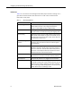
Configuring and Troubleshooting VoIP Monitoring Definitions Table 1 is a list of terms used throughout this white paper and their meanings. It is a good idea to become familiar with these terms in order to best understand this information in this paper. Table 1. 8 Terms and definitions Term Definition Built-in bridge A hardware component in many Cisco IP phones that allows audio streams to be merged and forked to support Unified CM Recording and Monitoring.
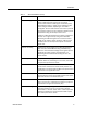
Introduction Table 1. Terms and definitions (cont’d) Term Definition Live monitoring A feature in CAD (also known as “silent monitoring”) that allows a CAD supervisor to listen in on a phone conversation between a CAD agent and another party. The CAD agent might or might not be notified that the call is being monitored, depending on how CAD is configured. The two audio streams that make up the call are captured and sent to the supervisor's desktop to be played back using the desktop's sound card.
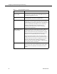
Configuring and Troubleshooting VoIP Monitoring Table 1. Terms and definitions (cont’d) Term Definition Session initiation protocol (SIP) A protocol used to set up and manage IP phone calls. This protocol is used when the Unified CM Recording and Monitoring feature is used. Soft IP phone A soft IP phone is a computer application that emulates a hard IP phone and runs on an agent's PC. SPAN Switched Port Analyzer.
Capturing an IP Phone Call Capturing an IP Phone Call In order to capture an IP phone call, we need access to the data travelling over the network and the format of the data. We will discuss the access issue later. In this section, we discuss the format of the audio portion of the phone call. Cisco Unified Communications Manager (Unified CM) and Unified Contact Center (Unified CC) software, in concert with Cisco switches, gateways, and routers, package audio phone calls as streams.
Configuring and Troubleshooting VoIP Monitoring The RTP packets are encapsulated in UDP, IP, and Ethernet envelopes as shown in Figure 3. Figure 3. Audio data encapsulation Audio data is also encoded using different formatting protocols. The audio format used has nothing to do with transport over a network, so it is not shown as an encapsulation in Figure 2. Cisco monitoring and recording software and hardware supports several audio data formats, including G.711 (mulaw and alaw), G.729, and G.722.
Accessing Audio Streams Accessing Audio Streams Accessing the streams of audio data is where things start to get complex. This is because network hardware and software and IP protocols themselves are created with an eye toward security. When packets of data are to be sent from endpoint A to endpoint B, we don't want other endpoints to see that data because it is considered private.
Configuring and Troubleshooting VoIP Monitoring The challenge then is to determine the best location to tap into this network to see the audio packets. The most reliable method is to have the phone itself send the audio streams to your software. This is possible with the Unified CM Recording and Monitoring feature. This feature, which is available on Unified CM 6.
Accessing Audio Streams If server monitoring on the switch is not supported due to hardware restrictions, policy, or the network design itself, another option for gaining access to the audio streams is the Unified CM monitoring feature found in Unified CM version 6.0(1) and later. This feature allows software to send a command to the agent IP phone, instructing it to send copies of the audio streams to two ports of a network endpoint.
Configuring and Troubleshooting VoIP Monitoring Table 2.
Accessing Audio Streams Desktop Capture Method The desktop capture method relies upon the fact that many Cisco IP phones contain a small internal switch and a second network port on the back of the phone to which a computer can be daisy-chained.Figure 7 shows that this capture method can work with either a hard or soft IP phone. Figure 7. Desktop capture hardware configurations In this configuration, the IP phone and the computer are sharing a single network cable for their network configuration.
Configuring and Troubleshooting VoIP Monitoring The desktop software treats this soft IP phone as if it is a hard IP phone daisy-chained to the PC. The only difference is that the NIC does not need to be put into promiscuous mode for a soft IP phone, because the soft IP phone and the PC have the same IP address. As a result, the sniffing software automatically has access to all the audio packets when the agent is on a call. This capture mode is supported by CAD and Recording Solution software.
Accessing Audio Streams ■ A SPAN or port monitoring session configured that uses the IP phone's port as one of the session's source ports ■ A VoIP monitoring/recording service connected to the SPAN session’s destination port ■ Proper configuration of the Cisco and Cisco software that associates the agent's IP phone device with a VoIP monitoring/recording service Layer 2 Routing Device Restriction A Layer 2 routing device is any piece of networking hardware that causes the MAC address used in a packet
Configuring and Troubleshooting VoIP Monitoring recording server reads the audio streams and writes the data to disk so the call can be listened to at a later time. Figure 8. Unified CM recording Referring to the numbered devices in Figure 8, the sequence is as follows: 1. The agent receives a call from a remote caller (1 > 2 > 3 > 4 > 7). 2. The Unified CM sends a SIP message to a recording server inviting it to accept copies of the audio streams for the agent’s call (5 > 4> 6). 3.
Accessing Audio Streams the built-in bridge on the agent's phone to duplicate and merge the two audio streams, make a call to the supervisor's phone, and start sending the audio stream. The live monitoring session ends when the original call ends, the supervisor hangs up, or the supervisor transfers the call to another party. Referring to the numbered devices in Figure 8 on page 20, the sequence is as follows: 1. The agent accepts a call from a remote caller (1 > 2 > 3 > 4 > 7). 2.
Configuring and Troubleshooting VoIP Monitoring data, they would capture these extra streams, resulting in duplicate audio packets and poor audio quality. Note that Recording Solution is still able to record using the server-based capture method even if the Unified CM method is used because it looks at the IP addresses and ports of the two streams. The additional audio stream will be ignored.
Deployment Issues 2 Introduction Deploying Cisco monitoring and recording software and properly configuring the software and network components can become quite complex. The method of audio capture that is used for the agents is only one aspect of a deployment, but whatever is decided can affect the amount of time and money required for a successful deployment.
Configuring and Troubleshooting VoIP Monitoring that allows the user to access network resources as if they were connected directly to the contact center's network. Figure 9. Remote agent configuration Two types of remote VPN agents are supported by the Cisco software: ■ If the remote agent has a hard IP phone, the agent must use a supported VPN router (for example, the Cisco 831 or 871 home office routers).
Introduction The Unified CM capture method (for monitoring only, not recording) is supported for CAD live monitoring, Recording Solution network recording, and Recording Solution live monitoring. If Cisco IP Communicator is used, it must support the Unified CM feature (version 7.0(1) or later). Mobile Agents Issue: The server capture method must be used for mobile agents This deployment model applies to Unified Contact Center Enterprise systems only.
Configuring and Troubleshooting VoIP Monitoring When a call is to be delivered to the mobile agent, the system uses the assigned CTI port to make a call to the agent’s configured phone. The call is then connected to the caller. The audio data for this call flows through the mobile agent voice gateway.
Introduction supports on-demand recording using the server capture method. Although the software runs on a PC, the Java code runs in a browser and does not have access to the system resources needed to support the desktop capture method. ■ Cisco IP Phone Agent (IPPA). IPPA is a service application that runs on the IP phone itself to enable contact center agents who do not have PCs to function as CAD agents.
Configuring and Troubleshooting VoIP Monitoring Table 3.
Introduction NDIS-Compliant NICs Issue: NICs that do not support promiscuous mode packet capturing will prevent monitoring and recording from working. NOTE: The Unified CM capture method of monitoring and recording does not depend on promiscuous mode to work. The information in this section pertains only to the desktop- and server-based capture methods.
Configuring and Troubleshooting VoIP Monitoring The following phone settings must be enabled in Unified CM for desktop packet capture to work: ■ PC Port. If this is not enabled, the second network port on the back of the phone will simply not work as a network connection for the user's PC. ■ PC Voice VLAN Access. Voice and data traffic can be segregated into separate VLANs in order to best use the networking resources.
Introduction Figure 11. Example of a port monitor configuration In Figure 11, the eight IP phones are plugged into ports 1–8 on the switch. The server is plugged into port 9 and is running the packet capture software. SPAN is configured on the switch to use ports 1—8 as the source ports and port 9 as the SPAN destination port.
Configuring and Troubleshooting VoIP Monitoring RSPAN Issue: The RSPAN feature is not supported on all switch models. Because switches have a limited number of physical ports to which IP phones and computers can attach, most networks contain multiple switches. These switches are interconnected, either directly or through routers and gateways, to create the network.
Introduction Figure 12. Using RSPAN to capture traffic from IP phones on multiple switches If one or more of the switches in the network do not support RSPAN but have agent phones connected, the only other option is to add another VoIP Monitor server to the installation and connect it to the switch, configuring another SPAN session on that switch as shown in Figure 13.
Configuring and Troubleshooting VoIP Monitoring Figure 13. Multiple switch configuration when RSPAN is not supported SPAN and RSPAN can both be used in an installation and might be required due to switch models or RSPAN support. For a list of Cisco switches that support RSPAN, refer to Appendix A. VLANs Issue: VLANs can be used to overcome network complexity if configured correctly. Virtual LANs, or VLANs, are an option for the source of a SPAN session.
Introduction audio streams when the agent is on a call. When SPAN is configured and uses a VLAN as a source, the voice VLAN is the one that is selected so only voice traffic is sent to the VoIP server for processing. There are other reasons for using voice VLANs in SPAN configurations as discussed in the section, "Server Capacity" on page 46. In Figure 13, all the IP phones connected to the three switches shown could be grouped into a VLAN that only carries voice traffic. We could call this Voice VLAN 10.
Configuring and Troubleshooting VoIP Monitoring Assume that the three IP phones, each connect to a port on a different switch and are all part of voice VLAN 100. The VoIP Monitor server is connected to switch 1. SPAN is configured on switch 1 to copy all the network traffic for the devices in VLAN 100 to the port connecting the VoIP Monitor server. If phone 3 calls phone 2, the voice traffic flows between the devices and switch 2 and switch 3.
Introduction Figure 15. Capturing ingress and egress traffic for two devices in the same SPAN configuration Figure 15 shows the To-Agent and From-Agent audio streams for two IP phones connected to the same switch, where both phone ports are source ports for a SPAN configuration. During a call between these two devices, the packet streams entering and exiting a SPANned port are copied to the SPAN destination port. We see that streams 1 through 4 are copied and sent to the VoIP Monitor server.
Configuring and Troubleshooting VoIP Monitoring Figure 16. Capturing egress-only traffic for two devices in the same SPAN configuration As can be see in Figure 16, only the audio streams exiting the IP phone's switch port are copied to the SPAN destination port. Alternately, the SPAN can be configured to capture only ingress traffic. In that case, streams 1 and 4 are copied to the VoIP Monitor server. This situation can occur for SPAN configurations using VLANs for sources and for RSPAN configurations.
Introduction stream with the external caller's voice is exiting the phone's switch port. The agent's voice stream is coming into the phone's port and is ignored due to the egress-only SPAN setting. This is shown in Figure 17. Figure 17. Egress-only SPAN issue for non-monitored port In Figure 17, audio stream 2 is the only stream of packets that is going out of the phone's port that is part of the SPAN configuration, so it is the only stream that is sent to the VoIP Monitor server.
Configuring and Troubleshooting VoIP Monitoring Figure 18. Ingress-only SPAN issue resolution In Figure 18, the SPAN configuration (using egress-only) was changed to include the port used to connect phones from the network cloud. Now we are able to see both audio streams that make up the call between the internal agent and external caller. Stream 3 is the agent's voice that exits the switch port connected to the external network.
Introduction different parties can be on the same call. How does this look to the packet capturing software? Figure 19. Audio streams for a two-party call In a normal two-party call, the phones send their stream directly to the other device over the network. Whenever a call is made into a conference call by adding parties, Cisco Unified CM software is responsible for merging the audio data from multiple parties so the phones that are part of the conference call still only see two streams.
Configuring and Troubleshooting VoIP Monitoring The important point here is that the audio streams sent out by all the phones on the conference call are directed to the Unified CM server port rather than directly to the other phone. The streams that arrive at the IP phones now come from the Unified CM port rather than from another phone directly. This is important if gateway SPAN sniffing is being used. Gateway SPAN Sniffing Issue: Agent-to-agent calls are not captured.
Introduction In the configuration shown in Figure 21, the same SPAN configuration would work for 1, 4, or 48 phones connected to the switch. When you look at this example, you might note that, by capturing both ingress and egress packets on both the voice gateway and the Unified CM port, duplicate streams will be captured.
Configuring and Troubleshooting VoIP Monitoring . Figure 22. Invalid hardware configuration A Layer 2 routing device is any networking hardware that changes the MAC address of a packet as it traverses the network. Routers, gateways, bridges, and hubs are all examples of Layer 2 routing devices. Just about anything other than a network repeater will cause the MAC address of packets flowing through it to change.
Introduction Figure 23. MAC address alteration by network routing To illustrate this, Figure 23 shows an IP phone connected to a router, then connected to a switch. A VoIP server is connected to the same switch and SPAN is configured to capture traffic on the port to which the router is connected. When on a call with another phone, the phone sends out a packet of audio data addressed to the other IP phone at 192.168.252.33.
Configuring and Troubleshooting VoIP Monitoring When the SPAN session copies the packet that hits the port it is monitoring and sends it to the VoIP server port, the packet capturing software looks at the packet's source and destination MAC address. Since the source MAC was changed to 112233445566, the software discards the packet. This continues and the packet capturing software never sees an audio packet that contains the MAC address it is looking for.
Introduction Network Traffic Restrictions on Destination Ports Issue: Some switches do not support normal network traffic on SPAN destination ports. Normally, a computer or phone connects to a switch port and that port is used to send and receive data from the network. On some switches, a port used as a destination of a SPAN configuration cannot be used to send or receive network traffic (other than the traffic sent to the port by the SPAN configuration).
Configuring and Troubleshooting VoIP Monitoring Examples of Deployment Planning This section brings the information previously discussed together and applies it to the task of planning a deployment of Cisco software that includes VoIP capturing software to support monitoring and/or recording. The first thing to do is gather information about the customer’s contact center and the desired functionality of the Cisco software.
Examples of Deployment Planning In the examples below, several fictional customer deployments will be examined as a Cisco software deployment is planned. Example 1: ABC Company Deployment Scenario: Small, simple deployment ABC Company is a small company that has a contact center with 10 agents. These agents are all on-site, have PCs at their workstations, and use Cisco IP phones.
Configuring and Troubleshooting VoIP Monitoring The preferred capture method is desktop capture because it is the easiest to configure and deploy. Since they don't have any mobile agents and their agents have PCs daisy-chained with their IP phones, we should be able to use desktop monitoring for all the agents. An alternate approach is to use Recording Solution network recording (if ABC Company purchases Recording Solution as well as CAD).
Examples of Deployment Planning we can buy and install supported NICs in all the agent machines, or we can choose to use the server capture method instead. To do this, we can set up a single SPAN configuration on their Catalyst 4500 switch to use all the IP phone ports as source ports and the port used by the VoIP server as the destination port.
Configuring and Troubleshooting VoIP Monitoring Table 6. International Sprockets questionnaire (cont’d) Question Answer How many agents use soft IP phones on their desktop? 0 Figure 25. International Sprockets network diagram Although the agents in the branch offices are widely scattered geographically, the network is still fairly simple. Recording Solution supports both desktop and server capture methods for remote agents using VPN connectivity.
Examples of Deployment Planning phones and the Recording Solution network recording server and concern over the WAN bandwidth between the phones and server. If necessary, due to incompatible NICs at the branch offices, a small number of agents could be configured to use network recording. Example 3: Redundant Systems Inc.
Configuring and Troubleshooting VoIP Monitoring Table 7. Redundant Systems questionnaire (cont’d) Question Answer How many contact center sites are there? 1 Is agent-to-agent recording or monitoring required? Rec: Yes Mon: No Do agents with desktops share a network connection with their IP phone? Yes How many agents use soft IP phones on their desktop? 64 Figure 26. Redundant Systems network diagram We also find out that ■ 54 Only the agents on the third floor will be monitored.
Examples of Deployment Planning ■ The Catalyst 6500 switches are redundantly connected. Only one is active at any one time. If one switch goes down, the other switch becomes active immediately. Any VoIP servers used for recording calls will also need to be redundant. ■ The agents with PCs have NICs that are NDIS compliant and support promiscuous mode packet capturing. ■ The current installation includes two CAD VoIP Monitor servers as shown in Figure 26.
Configuring and Troubleshooting VoIP Monitoring servers to the core switches as shown in Figure 27. Figure 27. VoIP server deployment at Redundant Systems An RSPAN VLAN is created that includes all the ports that are also in voice VLAN 2 and 3. We will use this RSPAN VLAN in the SPAN sessions we will create. The mobile agents will be configured as specified for each Cisco product.
Examples of Deployment Planning We could also connect two CAD VoIP servers to the core 6500 switches. Since the Catalyst 6500 switch can support 30 SPAN sessions, we can easily add another one that is used only by the CAD VoIP servers. This would require two CAD VoIP servers to be redundant. In this example, the second option of connecting the CAD VoIP servers to the core 6500 switches is selected.
Configuring and Troubleshooting VoIP Monitoring 58 November 2013
The NIC Qualification Utility 3 Overview The Network Interface Card Qualification (NICQ) utility is included with CAD, starting with the following versions: ■ CAD 6.6(1) for Unified CCX 7.0(1) ■ CAD 7.5(1) for Unified CCE 7.5(1) This utility is not a general NIC-qualifying tool. It is intended to be used exclusively with CAD installations.
Configuring and Troubleshooting VoIP Monitoring The service's NIC card should allow Promiscuous Mode packet capturing. This is true for most NIC cards, but there are some cards that will not allow network traffic sent to the IP phone to be seen by the packet sniffing software. You can validate the NIC without using the NIC Qualification (NICQ) utility.
Assumptions Assumptions It is assumed that the computer being tested is configured correctly, using either desktop monitoring or server monitoring. November 2013 ■ In desktop monitoring, an agent’s desktop is daisy-chained to the IP phone, then connected to the switch. RTP packets are captured by the packet-sniffing driver located on the desktop.
Configuring and Troubleshooting VoIP Monitoring Utility Syntax The syntax for the NICQ utility is: NICQ.exe [-?] [-o outfile] [-t seconds] [-p ipaddr] [-s] Table 8 defines the available parameters. Table 8. NICQ.exe parameters Parameter Description -? Causes the usage screen to be displayed. -o Defines the name of the file that will receive the results of the tests. By default, the file is named NICQ_Output.txt and is placed in the current folder.
Utility Syntax ■ Type 2 if your configuration uses SPAN (server monitoring) to send RTP traffic to the NIC. 5. The NICQ utility performs its testing. As it runs, it displays progress messages on the screen and writes detailed information to the output file. 6. After the utility stops, view the output file for detailed test results. Output From the NIC Qualification Tool By default, all test results and system information are written to a file named NICQ_Output.txt.
Configuring and Troubleshooting VoIP Monitoring 64 — Software Environment — Internet Settings — Office 2003 Applications November 2013
NICQ Tests NICQ Tests This section describes the functional areas that are tested and the specific tests that are run. The tests are executed in the order shown.
Configuring and Troubleshooting VoIP Monitoring These packet-sniffing tests are meant to verify that the NIC can be put into promiscuous mode in order to sniff network traffic not destined for the NIC card being tested. This is a basic requirement of the sniffing design used by CAD.
NICQ Tests If you have more than one IP phone connected inline with the NIC, only one of them is reported, not both.
Configuring and Troubleshooting VoIP Monitoring Test 5—Detect Promiscuous Traffic This test uses the data captured in Test 3. It verifies if the NIC supports promiscuous mode captures, and if valid RTP packets can be captured. Test Check for promiscuous traffic Corrective Action if Test Fails • Verify that a daisy-chained phone is configured to send voice traffic out its second network port • Ensure that the capture time is long enough. Use the -t parameter to increase the time, if necessary.
NICQ Tests IP: 10.0.9.162 Test 2: SUCCESS -------------------------------------------------------------Test 3: Attempt to sniff packets on all valid network adapters -------------------------------------------------------------Device: \Device\Splkpc_{1AF9AAEF-7AD0-4795-98EB-11AA0C59A106} (10.10.49.117) Packet capture completed successfully ---------------------------------------------------------Sender Receiver Count Packet Type ---------------------------------------------------------10.10.50.104 10.10.
Configuring and Troubleshooting VoIP Monitoring Boot Load ID: Version: Model Number: PC03A300 8.0(4.0) CP-7940 TFTP Server: Operational VLAN ID: CallManager 1: CallManager 2: CallManager 3: CallManager 4: CallManager 5: DHCP Enabled: PC Port Disabled: SW Port Configuration: PC Port Configuration: Voice VLAN Enabled: Security Mode: 172.17.12.20 110 SPLKCCMS Active SPLKCCMP Standby Yes No AUTO AUTO Yes Non Secure ** Network Port Details ** Neighbor Device ID: Switch10_4.spanlink.
Using Multiple NICs with the VoIP Monitor Service Using Multiple NICs with the VoIP Monitor Service The VoIP Monitor service sniffs RTP traffic from the network and sends it to registered clients. This requires support from the switch to which the service is connected. The VoIP Monitor service must be connected to the destination port of a configured SPAN/RSPAN.
Configuring and Troubleshooting VoIP Monitoring Limitations CAD’s packet sniffing library works only with NICs that are bound to TCP/IP. Make sure the sniffing card is bound to TCP/IP. In a Unified CCX environment, VoIP Monitor Service is only supported on the CCX unit.
Issues Issues The VoIP Monitor service explicitly specifies what NIC adapter to use for capturing audio packets, but it does not specify which NIC should be used when sending out packets. These outgoing packets would be going to either the Cisco Recording & Playback Service or a supervisor’s desktop that is live-monitoring an agent’s call. This is not a problem when using a single NIC for both sniffing and normal traffic.
Configuring and Troubleshooting VoIP Monitoring Installing a Second NIC in a VoIP Monitor Service Server To install a second NIC on a VoIP Monitor service computer: 1. Shut down the computer. 2. Install the second NIC in the computer. 3. Start the computer. 4. Make sure that neither adapter is using dynamic host configuration protocol (DHCP) to get its IP address. 5. Assign valid IP addresses to the adapters. 6. Determine which of the two adapters will be used for sniffing. 7.
Installing a Second NIC in a VoIP Monitor Service Server Configuration Setup utility to point to the correct packet sniffing NIC, the live monitoring and recording features might not work. You do not need to perform these additional steps in a single-NIC system after you install CAD. If you uninstall and reinstall the packet sniffing NIC in a single-NIC system or install a different packet sniffing NIC in a single-NIC system, use the CAD Configuration Setup utility as described above.
Configuring and Troubleshooting VoIP Monitoring 76 November 2013
Troubleshooting VoIP Monitoring and Recording 4 Introduction The steps required to configure VoIP monitoring and recording can be complex. This chapter describes some of the issues that can occur and methods for resolving them in the CAD and Recording Solution products. Incomplete or incorrect software and hardware configuration is the cause of 90% of all monitoring and recording problems. If the software has been installed correctly, monitoring and recording problems are rare.
Configuring and Troubleshooting VoIP Monitoring Troubleshooting This section helps you troubleshoot problems with VoIP monitoring and recording that occur in CAD and Recording Solution. Identifying the Problem’s Location Figure 28 displays the major components involved when the live monitoring or recording features are used in CAD and Recording Solution. Components for all types of monitoring and recording are shown.
Troubleshooting Possible causes of failure in monitoring/recording1 (cont’d) Table 9. No.
Configuring and Troubleshooting VoIP Monitoring Table 9. 80 Possible causes of failure in monitoring/recording1 (cont’d) No.
Troubleshooting Possible causes of failure in monitoring/recording1 (cont’d) Table 9. No.
Configuring and Troubleshooting VoIP Monitoring Possible causes of failure in monitoring/recording1 (cont’d) Table 9. No.
Troubleshooting If you are experiencing an issue that is related to live monitoring and recording, choose the issue listed in the table that is most similar to your issue, then refer to the instructions on the corresponding page. Table 10.
Configuring and Troubleshooting VoIP Monitoring Agent not on the Live Monitoring agent list Problem. The supervisor wants to live monitor a specific agent, but cannot find that agent on the list of agents available to live monitor. Cause. The most common cause for this is that the agent is not configured for network recording. Live monitoring is available only when the Unified CM monitoring and recording feature is used and properly configured for the agent’s device.
Troubleshooting Agent calls not recorded Problem. Calls for a Recording Solution agent or knowledge worker are not being recorded as expected. Recordings are blank. Cause. The most common cause for this is Recording Solution workflow configuration. The workflows assigned to an agent contain conditions that indicate which calls to record and keep. Generally, all calls are recorded, and the logic for deciding whether to keep to recorded call or not takes place at the end of the day.
Configuring and Troubleshooting VoIP Monitoring For server capture 1. Verify that the NIC supports promiscuous mode packet capturing. 2. Verify that SPAN is configured correctly on the switch to get audio traffic from the agent’s phone. For network capture 1. Verify the SIP trunk configuration on the Unified CM to make sure that the agent device is properly associated with the correct SIP trunk and that the SIP trunk is sending SIP messages to the correct Recording Solution Recording service. 2.
Troubleshooting Other causes of this issue include drops in audio during call control events. When a call is put on hold, transferred, or conferenced, a series of CTI events are sent to interested parties to process. Recording Solution sees these CTI events, and in response to them, RTP streams are stopped, started, and recreated. This forces Recording Solution to use different filters for capturing the correct audio traffic.
Configuring and Troubleshooting VoIP Monitoring ■ Built-in-Bridge (BiB) or Dual Media Streaming (DMS) is enabled on the agent’s phone. BiB and DMS are not supported in CAD before version 8.5(1). These features should be disabled in Unified CM. Portions of an audio call are missing Problem. Large sections of a call’s audio are missing. Usually the missing section is at the beginning of the call or at the end of the call.
Troubleshooting Procedures Troubleshooting Procedures This section describes the following procedures.
Configuring and Troubleshooting VoIP Monitoring 4. Click Properties to view your sound card’s properties. 5. Click Troubleshooting and follow the instructions given in the Troubleshooter. Verifying Registry Settings For monitoring to work correctly in CAD and Recording Solution, there are a few settings in the Windows registry that are required. The most important entry to look at is the Monitor Device entry. This is the network adapter that is used to sniff voice packets from the network.
Troubleshooting Procedures ■ For Recording Solution: QMDump.exe You will be presented with a list of adapters that can be used for sniffing voice traffic. 3. If you see the adapter that matches the Monitor Device entry in the Registry, select it and press Enter. 4. Let the program run for a short while and note whether any network traffic is captured.
Configuring and Troubleshooting VoIP Monitoring Opening a TAC Case If you are unable to discover why you cannot successfully monitor or record agent calls after looking at the debug files, you can open a TAC case.
Cisco Catalyst Switch Capabilities A The VoIP Monitor service is targeted specifically at the Cisco line of Catalyst switches. It might work with other switches that offer VoIP traffic, but it has not been tested on switches other than the Catalyst switch. It is important to be aware of the differences among the Catalyst switches when using the server capture method and configuring SPAN. In addition, the version of operating system software running on the switch can affect the features related to SPAN.
Configuring and Troubleshooting VoIP Monitoring Table 11.
Table 11.
Configuring and Troubleshooting VoIP Monitoring RSPAN This column shows whether the switch allows a SPAN destination port on one switch to get traffic from a port on another switch. VSPAN This column shows whether the switch supports SPAN configurations where VLANs are used to indicate the source traffic rather than having to specify individual ports.
Supported IP Phones B This appendix contains a list of the Cisco IP phones that are required in order to support a specific packet capture method used by Cisco software. Desktop Capture Method ■ Cisco IP Communicator Soft Phone v1.
Configuring and Troubleshooting VoIP Monitoring Unified CM Capture Method CAD and Recording Solution support any IP phone that Unified CM supports for the Unified CM Recording and Monitoring feature. This includes the following phone models: 98 ■ 7906 ■ 7911 ■ 7921 ■ 7925 ■ 7941 ■ 7942 ■ 7945 ■ 7961 ■ 7962 ■ 7965 ■ 7970 ■ 7971 ■ 7975 ■ Cisco IP Communicator v7.0.2.
Configuring Unified CM for VoIP Monitoring C The following settings are required to use VoIP monitoring for CAD and Recording Solution. The settings are configured in the Unified CM Administration web application. Configuring Unified CM for Desktop Monitoring The following settings are required for desktop monitoring. NOTE: Not all devices or versions of Unified CM use all of the settings described below. Configure the settings that appear for your device and version of Unified CM.
Configuring and Troubleshooting VoIP Monitoring Configuring Unified CM for Server Monitoring The following device setting is required for server monitoring to function correctly. In the Device Information section of the Device Configuration screen, set the Device Security Mode to Non-Secure or Authenticated. If it is set to Encrypted, the voice streams can be seen but will not be converted correctly, causing the speech to be garbled.
send those packets to the VoIP Monitor service, and the conversation cannot be heard. For this reason, monitoring and recording calls from one mobile agent to another mobile agent is not supported. November 2013 ■ Mappings between the agent voice gateways and VoIP Monitor services must be configured using Cisco Desktop Administrator. For instructions, see the section about mobile agent monitoring in the Cisco Desktop Administrator User Guide.
Configuring and Troubleshooting VoIP Monitoring 102 November 2013