Layer 2 Tunnel Protocol Version 3 The Layer 2 Tunnel Protocol Version 3 feature expands on Cisco support of the Layer 2 Tunnel Protocol Version 3 (L2TPv3). L2TPv3 is an Internet Engineering Task Force (IETF) l2tpext working group draft that provides several enhancements to L2TP for the capability to tunnel any Layer 2 payload over L2TP. Specifically, L2TPv3 defines the L2TP protocol for tunneling Layer 2 payloads over an IP core network using Layer 2 virtual private networks (VPNs).
Layer 2 Tunnel Protocol Version 3 Contents 12.0(28)S 12.0(29)S 12.
Layer 2 Tunnel Protocol Version 3 Prerequisites for Layer 2 Tunnel Protocol Version 3 Prerequisites for Layer 2 Tunnel Protocol Version 3 • Before you configure an Xconnect attachment circuit for a customer edge (CE) device (see the section “Configuring the Xconnect Attachment Circuit”), the CEF feature must be enabled. To enable CEF on an interface, use the ip cef or ip cef distributed command. • You must configure a loopback interface on the router for originating and terminating the L2TPv3 traffic.
Layer 2 Tunnel Protocol Version 3 Restrictions for Layer 2 Tunnel Protocol Version 3 • Enhanced 4-port synchronous serial port adapter • 8-port synchronous serial port adapter • Single-port HSSI adapter • Dual-port HSSI adapter • Single-port enhanced OC3 ATM port adapter • 8-port multichannel E1 G.703/G.704 120-ohm interfaces • 2-port multichannel E1 G.703/G.
Layer 2 Tunnel Protocol Version 3 Restrictions for Layer 2 Tunnel Protocol Version 3 • The number of sessions on a PPP, high-level data link control (HDLC), Ethernet, or 802.1q VLAN port is limited by the number of interface descriptor blocks (IDBs) that the router can support. For PPP, HDLC, Ethernet, and 802.1q VLAN circuit types, an IDB is required for each circuit. When L2TPv3 is used to tunnel Frame Relay D channel data-link connection identifiers (DLCIs), an IDB is not required for each circuit.
Layer 2 Tunnel Protocol Version 3 Restrictions for Layer 2 Tunnel Protocol Version 3 • On the Cisco 10720 Internet router, the uti translation command is not migrated for Xconnect service and is not supported. Although the uti command is supported in L2TPv3 releases, the translation option is lost in the migration. • On the Cisco 10720 Internet Router, although it is not required, it is highly recommended that you configure a loopback interface as the IP local interface.
Layer 2 Tunnel Protocol Version 3 Restrictions for Layer 2 Tunnel Protocol Version 3 • On Engine 2 line cards, the input Frame Relay permanent virtual circuit (PVC) counters will not be updated. • The 8-port Fast Ethernet line card should not be connected to a hub or switch when L2TPv3 is configured on the ingress side of one or more of its ports, or duplicate packets will be generated, causing the router to be flooded with packets.
Layer 2 Tunnel Protocol Version 3 Restrictions for Layer 2 Tunnel Protocol Version 3 Backward explicit congestion notification (BECN) and forward explicit congestion notification (FECN) configuration are not supported. The Type of Service (ToS) byte must be configured in IP headers of tunneled Frame Relay packets when you configure the L2TPv3 pseudowire (see Configuring the L2TPv3 Pseudowire, page 34).
Layer 2 Tunnel Protocol Version 3 Restrictions for Layer 2 Tunnel Protocol Version 3 • Point-to-multipoint and multipoint-to-point configurations are not supported. There is a 1:1 relationship between an attachment circuit and an L2TPv3 session. ATM VP Mode Single Cell Relay over L2TPv3 Restrictions • The ATM VP Mode Single Cell Relay over L2TPv3 feature is supported only on the Cisco 7200 and Cisco 7500 series routers with ATM Deluxe PA-A3 interfaces.
Layer 2 Tunnel Protocol Version 3 Information About Layer 2 Tunnel Protocol Version 3 Protocol Demultiplexing for L2TPv3 Restrictions • IPv6 protocol demultiplexing is supported only for Ethernet and terminated DLCI Frame Relay interfaces. • Frame Relay demultiplexing is supported for point-to-point or multipoint. • FRF.12 end-to-end fragmentation is supported on the Cisco 7500 series routers only between the CE and the PE routers. • FRF.
Layer 2 Tunnel Protocol Version 3 Information About Layer 2 Tunnel Protocol Version 3 As described in the section “L2TPv3 Header Description,” the UTI data header is identical to the L2TPv3 header but with no sequence numbers and an 8-byte cookie.
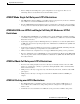
Layer 2 Tunnel Protocol Version 3 Information About Layer 2 Tunnel Protocol Version 3 Figure 1 L2TPv3 Operation Xconnected interface CE R3 Pseudowire tu1 int2 int1 PE R1 IP network e1 L2TPv3-based L2 tunnel Xconnected interface int3 e2 int4 CE R4 PE R2 Pseudowire tu2 L2TPv3 tunneled LAN LAN2 L2TPv3 tunneled LAN 80653 LAN1 In Figure 1, the PE routers R1 and R2 provide L2TPv3 services.
Layer 2 Tunnel Protocol Version 3 Information About Layer 2 Tunnel Protocol Version 3 L2TPv3 Header Description The migration from UTI to L2TPv3 also requires the standardization of the UTI header. As a result, the L2TPv3 header has the new format shown in Figure 2.
Layer 2 Tunnel Protocol Version 3 Information About Layer 2 Tunnel Protocol Version 3 Bit 1 indicates whether the Sequence Number field, bits 8 to 31, contains a valid sequence number and is to be updated. L2TPv3 Features L2TPv3 provides Xconnect support for Ethernet, 802.
Layer 2 Tunnel Protocol Version 3 Information About Layer 2 Tunnel Protocol Version 3 Multiple L2TP sessions (one for each forwarded Layer 2 circuit) can exist between a pair of PEs, and can be maintained by a single control channel. Session IDs and cookies are dynamically generated and exchanged as part of a dynamic session setup. Information such as sequencing configuration is also exchanged. Circuit state changes (UP/DOWN) are conveyed using the set link info (SLI) message.
Layer 2 Tunnel Protocol Version 3 Information About Layer 2 Tunnel Protocol Version 3 Cisco IOS Release 12.0(24)S introduced the ability to allow IP traffic from the CE router to be fragmented before the data enters the pseudowire, forcing the computationally expensive reassembly to occur in the CE network rather than in the service provider network. The number of fragments that must be generated is determined based on the discovered pseudowire path MTU.
Layer 2 Tunnel Protocol Version 3 Information About Layer 2 Tunnel Protocol Version 3 • If you enable the ip dfbit set command in the pseudowire class, the default MTU behavior changes so that any packets that cannot fit within the tunnel MTU are dropped. • If you enable the ip pmtu command in the pseudowire class, the L2TPv3 control channel participates in the path MTU discovery.
Layer 2 Tunnel Protocol Version 3 Information About Layer 2 Tunnel Protocol Version 3 L2TPv3 and UTI Feature Comparison Table 1 compares L2TPv3 and UTI support for the Cisco 7200 and Cisco 7500 series routers.
Layer 2 Tunnel Protocol Version 3 Information About Layer 2 Tunnel Protocol Version 3 Supported L2TPv3 Payloads L2TPv3 supports the following Layer 2 payloads that can be included in L2TPv3 packets tunneled over the pseudowire: Note • Frame Relay • Ethernet • 802.1q (VLAN) • HDLC • PPP • ATM • IPv6 Protocol Demultiplexing Each L2TPv3 tunneled packet includes the entire Layer 2 frame of the payloads described in this section.
Layer 2 Tunnel Protocol Version 3 Information About Layer 2 Tunnel Protocol Version 3 For example, in Figure 1, CE R3 and PE R1 are Frame Relay LMI peers; CE R4 and PE R2 are also LMI peers. You can use a different type of LMI between CE R3 and PE R1 compared to what you use between CE R4 and PE R2. The CE devices may be a Frame Relay switch or end-user device. Each Frame Relay PVC is composed of multiple segments.
Layer 2 Tunnel Protocol Version 3 Information About Layer 2 Tunnel Protocol Version 3 CIR Guarantees In order to provide committed information rate (CIR) guarantees, you can configure a queueing policy that provides bandwidth to each DLCI to the interface facing the customer network on the egress PE. Note CIR guarantees are supported only on the Cisco 7500 series with dCEF.
Layer 2 Tunnel Protocol Version 3 Information About Layer 2 Tunnel Protocol Version 3 • User priority field • Canonical format indicator (CFI) • A 12-bit VLAN ID (VID) For L2TPv3, an Ethernet subinterface configured to support VLAN switching may be bound to an Xconnect service so that all Ethernet traffic, tagged with a VID specified on the subinterface, is tunneled to another PE. The VLAN Ethernet frames are forwarded in their entirety.
Layer 2 Tunnel Protocol Version 3 Information About Layer 2 Tunnel Protocol Version 3 ATM VP Mode Single Cell Relay over L2TPv3 The ATM VP Mode Single Cell Relay over L2TPv3 feature allows cells coming into a predefined PVP on the ATM interface to be transported over an L2TPv3 pseudowire to a predefined PVP on the egress ATM interface. A single ATM cell is encapsulated into each L2TPv3 data packet.
Layer 2 Tunnel Protocol Version 3 Information About Layer 2 Tunnel Protocol Version 3 OAM Local Emulation Mode In OAM Local Emulation mode, OAM cells are not passed through the pseudowire. All F5 OAM cells are terminated and handled locally. On the L2TPv3-based pseudowire, the CE device sends an SLI message across the pseudowire to notify the peer PE node about the defect, rather than tearing down the session. The defect can occur at any point in the link between the local CE and the PE.
Layer 2 Tunnel Protocol Version 3 How to Configure Layer 2 Tunnel Protocol Version 3 Table 3 shows the valid combinations of configurations.
Layer 2 Tunnel Protocol Version 3 How to Configure Layer 2 Tunnel Protocol Version 3 • Configuring L2TPv3 Control Channel Authentication Parameters • Configuring L2TP Control Channel Maintenance Parameters After you enter L2TP class configuration mode, you can configure L2TP control channel parameters in any order. If you have multiple authentication requirements you can configure multiple sets of L2TP class control channel parameters with different L2TP class names.
Layer 2 Tunnel Protocol Version 3 How to Configure Layer 2 Tunnel Protocol Version 3 Step 3 Command or Action Purpose l2tp-class [l2tp-class-name] Specifies the L2TP class name and enters L2TP class configuration mode. • Example: Router(config)# l2tp-class class1 Step 4 receive-window size (Optional) Configures the number of packets that can be received by the remote peer before backoff queueing occurs.
Layer 2 Tunnel Protocol Version 3 How to Configure Layer 2 Tunnel Protocol Version 3 Support for the L2TPv3 Control Connection Authentication feature is introduced in Cisco IOS Release 12.0(29)S. Support for L2TP control channel authentication is maintained for backward compatibility. Either or both authentication methods can be enabled to allow interoperability with peers supporting only one of the authentication methods.
Layer 2 Tunnel Protocol Version 3 How to Configure Layer 2 Tunnel Protocol Version 3 Perform one or both of the following tasks to configure authentication parameters for the L2TPv3 control channel: • Configuring Authentication for the L2TP Control Channel, page 29 (optional) • Configuring L2TPv3 Control Channel Hashing, page 30 (optional) Configuring Authentication for the L2TP Control Channel The L2TP control channel method of authentication is the older, CHAP-like authentication system inherited fro
Layer 2 Tunnel Protocol Version 3 How to Configure Layer 2 Tunnel Protocol Version 3 Step 3 Command or Action Purpose l2tp-class [l2tp-class-name] Specifies the L2TP class name and enters L2TP class configuration mode. • Example: Router(config)# l2tp-class class1 Step 4 authentication The l2tp-class-name argument is optional. However, if you want to configure multiple L2TP classes you must specify a unique l2tp-class-name for each one.
Layer 2 Tunnel Protocol Version 3 How to Configure Layer 2 Tunnel Protocol Version 3 is too small. If the L2TPv3 Control Channel Hashing feature is enabled, message digest validation must be enabled. Message digest validation deactivates the data path received sequence number update and restricts the minimum local receive window size to 35. You may choose to configure control message authentication or control message integrity checking.
Layer 2 Tunnel Protocol Version 3 How to Configure Layer 2 Tunnel Protocol Version 3 Step 3 Command or Action Purpose l2tp-class [l2tp-class-name] Specifies the L2TP class name and enters L2TP class configuration mode. Example: • Router(config)# l2tp-class class1 Step 4 digest [secret [0 | 7] password] [hash {md5 | sha}] (Optional) Enables L2TPv3 control connection authentication or integrity checking.
Layer 2 Tunnel Protocol Version 3 How to Configure Layer 2 Tunnel Protocol Version 3 Step 5 Command or Action Purpose digest check (Optional) Enables the validation of the message digest in received control messages. • Example: Router(config-l2tp-class)# digest check Step 6 Note Validation of the message digest is enabled by default. Validation of the message digest cannot be disabled if authentication has been enabled using the digest secret command.
Layer 2 Tunnel Protocol Version 3 How to Configure Layer 2 Tunnel Protocol Version 3 DETAILED STEPS Step 1 Command or Action Purpose enable Enables privileged EXEC mode. • Enter your password if prompted. Example: Router> enable Step 2 configure terminal Enters global configuration mode. Example: Router# configure terminal Step 3 l2tp-class [l2tp-class-name] Specifies the L2TP class name and enters L2TP class configuration mode.
Layer 2 Tunnel Protocol Version 3 How to Configure Layer 2 Tunnel Protocol Version 3 To remove the command, you must delete the pseudowire with the no pseudowire-class command. To change the type of encapsulation, remove the pseudowire with the no pseudowire-class command and re-establish the pseudowire and specify the new encapsulation type. SUMMARY STEPS 1. enable 2. configure terminal 3. pseudowire-class [pw-class-name] 4. encapsulation l2tpv3 5. protocol {l2tpv3 | none} [l2tp-class-name] 6.
Layer 2 Tunnel Protocol Version 3 How to Configure Layer 2 Tunnel Protocol Version 3 Step 5 Command or Action Purpose protocol {l2tpv3 | none}[l2tp-class-name] (Optional) Specifies the L2TPv3 signaling protocol to be used to manage the pseudowires created with the control channel parameters in the specified L2TP class (see the section “Configuring L2TP Control Channel Parameters”).
Layer 2 Tunnel Protocol Version 3 How to Configure Layer 2 Tunnel Protocol Version 3 Step 8 Command or Action Purpose ip tos {value value | reflect} (Optional) Configures the value of the ToS byte in IP headers of tunneled packets, or reflects the ToS byte value from the inner IP header. Example: Router(config-pw)# ip tos reflect Step 9 • (Optional) Configures the value of the DF bit in the outer headers of tunneled packets.
Layer 2 Tunnel Protocol Version 3 How to Configure Layer 2 Tunnel Protocol Version 3 DETAILED STEPS Step 1 Command or Action Purpose enable Enables privileged EXEC mode. • Enter your password if prompted. Example: Router> enable Step 2 configure terminal Enters global configuration mode. Example: Router# configure terminal Step 3 interface type slot/port Specifies the interface by type (for example, Ethernet) and slot and port number, and enters interface configuration mode.
Layer 2 Tunnel Protocol Version 3 How to Configure Layer 2 Tunnel Protocol Version 3 Step 4 Command or Action Purpose xconnect peer-ip-address vcid pseudowire-parameters [sequencing {transmit | receive | both}] Specifies the IP address of the peer PE router and the 32-bit virtual circuit identifier shared between the PE at each end of the control channel. Example: • The peer router ID (IP address) and virtual circuit ID must be a unique combination on the router.
Layer 2 Tunnel Protocol Version 3 How to Configure Layer 2 Tunnel Protocol Version 3 Manually Configuring L2TPv3 Session Parameters When you bind an attachment circuit to an L2TPv3 pseudowire for Xconnect service using the xconnect l2tpv3 manual command (see the section “Configuring the Xconnect Attachment Circuit”) because you do not want signaling, you must then configure L2TP-specific parameters to complete the L2TPv3 control channel configuration. SUMMARY STEPS 1. enable 2. configure terminal 3.
Layer 2 Tunnel Protocol Version 3 How to Configure Layer 2 Tunnel Protocol Version 3 Step 5 Command or Action Purpose l2tp id local-session-id remote-session-id Configures the identifiers for the local L2TPv3 session and for the remote L2TPv3 session on the peer PE router.
Layer 2 Tunnel Protocol Version 3 How to Configure Layer 2 Tunnel Protocol Version 3 3. interface type slot/port 4. atm pvp vpi [l2transport] 5. xconnect peer-ip-address vcid pw-class pw-class-name DETAILED STEPS Step 1 Command or Action Purpose enable Enables privileged EXEC mode. • Enter your password if prompted. Example: Router> enable Step 2 configure terminal Enters global configuration mode.
Layer 2 Tunnel Protocol Version 3 How to Configure Layer 2 Tunnel Protocol Version 3 The ATM Single Cell Relay VC mode feature can be used to carry any type of AAL traffic over the pseudowire. It will not distinguish OAM cells from User data cells. In this mode, PM and Security OAM cells are also transported over the pseudowire. Perform this task to enable the ATM Single Cell Relay VC Mode over L2TPv3 feature. SUMMARY STEPS 1. enable 2. configure terminal 3. interface type slot/port 4.
Layer 2 Tunnel Protocol Version 3 How to Configure Layer 2 Tunnel Protocol Version 3 Step 5 Command or Action Purpose encapsulation aal0 Specifies ATM AAL0 encapsulation for the PVC. Example: Router(config-atm-vc)# encapsulation aal0 Step 6 xconnect peer-ip-address vcid pw-class pw-class-name Specifies the IP address of the peer PE router and the 32-bit VCI shared between the PE at each end of the control channel.
Layer 2 Tunnel Protocol Version 3 How to Configure Layer 2 Tunnel Protocol Version 3 DETAILED STEPS Step 1 Command or Action Purpose enable Enables privileged EXEC mode. • Enter your password if prompted. Example: Router> enable Step 2 configure terminal Enters global configuration mode. Example: Router# configure terminal Step 3 interface type slot/port Specifies the interface by type, slot, and port number, and enters interface configuration mode.
Layer 2 Tunnel Protocol Version 3 How to Configure Layer 2 Tunnel Protocol Version 3 2. configure terminal 3. interface type slot/port 4. atm mcpt-timers [timeout-value-1 timeout-value-2 timeout-value-3] 5. cell packing [cells] [mcpt-timer timer] 6. xconnect peer-ip-address vcid pseudowire-parameters [sequencing {transmit | receive | both}] DETAILED STEPS Step 1 Command or Action Purpose enable Enables privileged EXEC mode. • Enter your password if prompted.
Layer 2 Tunnel Protocol Version 3 How to Configure Layer 2 Tunnel Protocol Version 3 Configuring VP Mode ATM Cell Packing over L2TPv3 Perform this task to configure VP mode ATM cell packing over L2TPv3. SUMMARY STEPS 1. enable 2. configure terminal 3. interface type slot/port 4. atm mcpt-timers [timeout-value-1 timeout-value-2 timeout-value-3] 5. atm pvp vpi [peak-rate] [l2transport] 6. cell packing [cells] [mcpt-timer timer] 7.
Layer 2 Tunnel Protocol Version 3 How to Configure Layer 2 Tunnel Protocol Version 3 Step 6 Command or Action Purpose cell-packing [cells] [mcpt-timer timer] Enables the packing of multiple ATM cells into each L2TPv3 data packet. • cells—(Optional) The number of cells to be packed into an L2TPv3 data packet. The default number of ATM cells to be packed is the MTU of the interface divided by 52. • mcpt-timer timer—(Optional) Specifies which MCPT timer to use.
Layer 2 Tunnel Protocol Version 3 How to Configure Layer 2 Tunnel Protocol Version 3 Step 3 Command or Action Purpose interface type slot/port Specifies the interface by type, slot, and port number, and enters interface configuration mode. Example: Router(config)# interface ATM 4/1 Step 4 atm mcpt-timers [timeout-value-1 timeout-value-2 timeout-value-3] (Optional) Sets up the cell-packing timers, which specify how long the PE router can wait for cells to be packed into an L2TPv3 packet.
Layer 2 Tunnel Protocol Version 3 How to Configure Layer 2 Tunnel Protocol Version 3 Configuring the Xconnect Attachment Circuit for ATM AAL5 SDU Mode over L2TPv3 The ATM AAL5 SDU Mode feature maps the AAL5 payload of an AAL5 PVC to a single L2TPv3 session. This service will transport OAM and RM cells, but does not attempt to maintain the relative order of these cells with respect to the cells that comprise the AAL5 CPCS-PDU.
Layer 2 Tunnel Protocol Version 3 How to Configure Layer 2 Tunnel Protocol Version 3 Step 5 Command or Action Purpose encapsulation aal5 Specifies ATM AAL5 encapsulation for the PVC. Example: Router(config-atm-vc)# encapsulation aal5 Step 6 xconnect peer-ip-address vcid pw-class pw-class-name Specifies the IP address of the peer PE router and the 32-bit VCI shared between the PE at each end of the control channel.
Layer 2 Tunnel Protocol Version 3 How to Configure Layer 2 Tunnel Protocol Version 3 SUMMARY STEPS 1. enable 2. configure terminal 3. interface type slot/port 4. pvc [name] vpi/vci [l2transport] 5. encapsulation aal5 6. xconnect peer-ip-address vcid pw-class pw-class-name 7. oam-ac emulation-enable [ais-rate] DETAILED STEPS Step 1 Command or Action Purpose enable Enables privileged EXEC mode. • Enter your password if prompted.
Layer 2 Tunnel Protocol Version 3 How to Configure Layer 2 Tunnel Protocol Version 3 Step 6 Command or Action Purpose xconnect peer-ip-address vcid pw-class pw-class-name Specifies the IP address of the peer PE router and the 32-bit VCI shared between the PE at each end of the control channel. • The peer router ID (IP address) and virtual circuit ID must be a unique combination on the router.
Layer 2 Tunnel Protocol Version 3 How to Configure Layer 2 Tunnel Protocol Version 3 Configuring Protocol Demultiplexing for Ethernet Interfaces Perform this task to configure the Protocol Demultiplexing feature on an Ethernet interface. SUMMARY STEPS 1. enable 2. configure terminal 3. interface type slot/port 4. ip address ip-address mask [secondary] 5. xconnect peer-ip-address vcid pw-class pw-class-name 6.
Layer 2 Tunnel Protocol Version 3 How to Configure Layer 2 Tunnel Protocol Version 3 Step 5 Command or Action Purpose xconnect peer-ip-address vcid pw-class pw-class-name Specifies the IP address of the peer PE router and the 32-bit VCI shared between the PE at each end of the control channel and enters Xconnect configuration mode. Example: • The peer router ID (IP address) and virtual circuit ID must be a unique combination on the router.
Layer 2 Tunnel Protocol Version 3 How to Configure Layer 2 Tunnel Protocol Version 3 Step 3 Command or Action Purpose interface type slot/port-adapter.subinterfacenumber [multipoint | point-to-point] Specifies the interface by type, slot, and port number, and enters interface configuration mode. Example: Router(config)# interface serial 1/1.2 multipoint Step 4 ip address ip-address mask [secondary] Sets a primary or secondary IP address for an interface. Example: Router(config-if)# ip address 172.
Layer 2 Tunnel Protocol Version 3 Configuration Examples for Layer 2 Tunnel Protocol Version 3 Configuration Examples for Layer 2 Tunnel Protocol Version 3 This section provides the following configuration examples: • Configuring Frame Relay DLCI-to-DLCI Switching Example, page 57 • Configuring Frame Relay Trunking Example, page 58 • Configuring QoS for L2TPv3 on the Cisco 7500 Series Example, page 58 • Configuring QoS for L2TPv3 on the Cisco 12000 Series Example, page 59 • Configuring MLFR for L2
Layer 2 Tunnel Protocol Version 3 Configuration Examples for Layer 2 Tunnel Protocol Version 3 interface Serial0/0 encapsulation frame-relay frame-relay intf-type dce connect one Serial0/0 100 l2transport xconnect 10.0.3.201 555 pw-class fr-xconnect connect two Serial0/0 200 l2transport xconnect 10.0.3.201 666 pw-class fr-xconnect Configuring Frame Relay Trunking Example The following is a sample configuration for setting up a trunk connection for an entire serial interface over a pseudowire.
Layer 2 Tunnel Protocol Version 3 Configuration Examples for Layer 2 Tunnel Protocol Version 3 Configuring QoS for L2TPv3 on the Cisco 12000 Series Example To apply a QoS policy for L2TPv3 to a Frame Relay interface on a Cisco 12000 series 2-port Ch OC-3/STM-1 (DS1/E1) or 6-port Ch T3 line card, you must: • Use the map-class frame-relay class-name command in global configuration mode to apply a QoS policy to a Frame Relay class of traffic.
Layer 2 Tunnel Protocol Version 3 Configuration Examples for Layer 2 Tunnel Protocol Version 3 policy-map o class d2 bandwidth percent 10 random-detect random-detect precedence 1 200 packets 500 packets 1 class d3 bandwidth percent 10 random-detect random-detect precedence 1 1 packets 2 packets 1 map-class frame-relay fr-map service-policy output o interface Serial0/1/1:0 encapsulation frame-relay frame-relay interface-dlci 100 switched class fr-map connect frol2tp1 Serial0/1/1:0 100 l2transport xconnect 1
Layer 2 Tunnel Protocol Version 3 Configuration Examples for Layer 2 Tunnel Protocol Version 3 interface Serial0/0 encapsulation frame-relay frame-relay intf-type dce service-policy output dlci connect one Serial0/0 100 l2transport xconnect 10.0.3.201 555 encapsulation l2tpv3 pw-class mqc connect two Serial0/0 200 l2transport xconnect 10.0.3.
Layer 2 Tunnel Protocol Version 3 Configuration Examples for Layer 2 Tunnel Protocol Version 3 interface Ethernet0/0.1 encapsulation dot1Q 5 xconnect 10.0.3.201 123 pw-class vlan-xconnect Configuring a Negotiated L2TPv3 Session for Local HDLC Switching Example The following is a sample configuration of a dynamic L2TPv3 session for local HDLC switching.
Layer 2 Tunnel Protocol Version 3 Configuration Examples for Layer 2 Tunnel Protocol Version 3 interface Serial 0/0/0 encapsulation frame-relay servicepolicy output SET-DE connect fr-mpls-100 serial 0/0/0 100 l2transport xconnect 10.10.10.10 pw-class l2tpv3 Matching the Frame Relay DE Bit Configuration Example The following example shows how to configure the service policy called match-de and attach it to an interface.
Layer 2 Tunnel Protocol Version 3 Configuration Examples for Layer 2 Tunnel Protocol Version 3 Configuring ATM Single Cell Relay VC Mode over L2TPv3 Example The following example shows how to configure the ATM Single Cell Relay VC Mode over L2TPv3 feature: pw-class atm-xconnect encapsulation l2tpv3 interface ATM 4/1 pvc 5/500 l2transport encapsulation aal0 xconnect 10.0.3.
Layer 2 Tunnel Protocol Version 3 Configuration Examples for Layer 2 Tunnel Protocol Version 3 Configuring the Xconnect Attachment Circuit for ATM AAL5 SDU Mode over L2TPv3 Example The following configuration binds a PVC to an Xconnect attachment circuit to forward ATM cells over an established L2TPv3 pseudowire: pw-class atm-xconnect encapsulation l2tpv3 interface ATM 4/1 pvc 5/500 l2transport encapsulation aal5 xconnect 10.0.3.
Layer 2 Tunnel Protocol Version 3 Configuration Examples for Layer 2 Tunnel Protocol Version 3 Configuring L2TPv3 Control Connection Authentication Examples The following example configures CHAP-style authentication of the L2TPv3 control channel: l2tp-class class1 authentication password cisco The following example configures control connection authentication using the L2TPv3 Control Channel Hashing feature: l2tp-class class1 digest secret cisco hash sha hidden The following example configures control co
Layer 2 Tunnel Protocol Version 3 Configuration Examples for Layer 2 Tunnel Protocol Version 3 Verifying an L2TP Control Channel Example To display detailed information the L2TP control channels that are set up to other L2TP-enabled devices for all L2TP sessions on the router, use the show l2tun tunnel all command. The L2TP control channel is used to negotiate capabilities, monitor the health of the peer PE router, and set up various components of an L2TPv3 session.
Layer 2 Tunnel Protocol Version 3 Configuration Examples for Layer 2 Tunnel Protocol Version 3 Verifying ATM AAL5 SDU Mode over L2TPv3 Configuration Example To verify the configuration of a PVC, use the show atm vc command in privileged EXEC mode: Router# show atm vc VCD/ Interface 2/0 2/0 Name pvc 4 VPI 9 9 VCI 900 901 Type PVC PVC Encaps AAL5 AAL5 Peak Kbps 2400 149760 Avg/Min Kbps 200 N/A Burst Cells Sts UP UP The following show l2tun session command output displays information about ATM VC mo
Layer 2 Tunnel Protocol Version 3 Additional References Verifying ATM VCC Cell Relay over L2TPv3 Example The following show atm vc command output displays information about VCC cell relay configuration: Router# show atm vc VCD/ Interface 2/0 Name 4 VPI 9 VCI 901 Type PVC Peak Kbps 149760 Encaps AAL0 Avg/Min Kbps N/A Burst Cells Sts UP The following show l2tun session command output displays information about VCC cell relay configuration: Router# show l2tun session all Session Information Total tu
Layer 2 Tunnel Protocol Version 3 Additional References Related Topic Document Title Configuring CEF “Cisco Express Forwarding” chapter in the Cisco IOS Switching Configuration Guide, Release 12.0 MTU discovery and packet fragmentation MTU Tuning for L2TP Tunnel Marking for L2TPv3 Tunnels QoS: Tunnel Marking for L2TPv3 Tunnels Multilink Frame Relay over L2TPv3/AToM Multilink Frame Relay over L2TPv3/AToM Additional VPN commands: complete command Cisco IOS Release 12.
Layer 2 Tunnel Protocol Version 3 Command Reference Technical Assistance Description Link Technical Assistance Center (TAC) home page, containing 30,000 pages of searchable technical content, including links to products, technologies, solutions, technical tips, and tools. Registered Cisco.com users can log in from this page to access even more content. http://www.cisco.com/public/support/tac/home.shtml Command Reference This section documents new and modified commands.
Layer 2 Tunnel Protocol Version 3 Command Reference • match fr-de • match protocol • password • protocol • pseudowire-class • receive-window • retransmit • sequencing • show atm cell-packing • show l2tun session • show l2tun tunnel • snmp-server enable traps l2tun session • timeout setup • xconnect Cisco IOS Releases 12.0(29)S and 12.
Layer 2 Tunnel Protocol Version 3 atm mcpt-timers atm mcpt-timers To set up the cell-packing timers, which specify how long the provider edge (PE) router can wait for cells to be packed into a Multiprotocol Label Switching (MPLS) or Layer 2 Tunneling Protocol version 3 (L2TPv3) packet, use the atm mcpt-timers command in interface configuration mode. To disable the cell-packing timers, use the no form of this command.
Layer 2 Tunnel Protocol Version 3 atm mcpt-timers Related Commands Command Description cell-packing Enables ATM cell relay to pack multiple ATM cells into each MPLS or L2TPv3 packet. debug atm cell-packing Displays ATM cell relay cell packing debugging information. show atm cell-packing Displays information about the VCs and VPs that have ATM cell relay over MPLS or L2TPv3 cell packing enabled. Cisco IOS Releases 12.0(29)S and 12.
Layer 2 Tunnel Protocol Version 3 atm pvp atm pvp To create a permanent virtual path (PVP) used to multiplex (or bundle) one or more virtual circuits (VCs), use the atm pvp command in interface configuration mode. To remove a PVP, use the no form of this command. atm pvp vpi [peak-rate] [l2transport] no atm pvp vpi Syntax Description vpi ATM network virtual path identifier (VPI) of the VC to multiplex on the permanent virtual path. The range is from 0 to 255.
Layer 2 Tunnel Protocol Version 3 atm pvp Changing the peak-rate argument causes the ATM-CES port adapter to go down and then back up. When you create a PVP, two VCs are created (VCI 3 and 4) by default. These VCs are created for VP end-to-end loopback and segment loopback operation, administration, and maintenance (OAM) support. When you use the l2transport keyword with the atm pvp command, the router enters l2transport PVP configuration mode.
Layer 2 Tunnel Protocol Version 3 authentication authentication To enable Layer 2 Tunnel Protocol Version 3 (L2TPv3) Challenge Handshake Authentication Protocol (CHAP) style authentication, use the authentication command in L2TP class configuration mode. To disable L2TPv3 CHAP-style authentication, use the no form of this command. authentication no authentication Syntax Description This command has no arguments or keywords. Defaults L2TPv3 CHAP-style authentication is disabled.
Layer 2 Tunnel Protocol Version 3 authentication Table 5 Compatibility Matrix for L2TPv3 Authentication Methods PE1 Authentication Configuration PE2 Supporting Old Authentication1 PE2 Supporting New Authentication2 PE2 Supporting Old and New Authentication3 None None None None New integrity check New integrity check — Old authentication Old authentication Old authentication Old authentication and new authentication Old authentication and new integrity check New authentication — New integ
Layer 2 Tunnel Protocol Version 3 authentication Related Commands Command Description l2tp-class Creates a template of L2TP control plane configuration settings that can be inherited by different pseudowire classes and enters L2TP class configuration mode. digest Enables L2TPv3 control connection authentication or integrity checking. password Configures the password used by a PE router for CHAP-style L2TPv3 authentication. Cisco IOS Releases 12.0(29)S and 12.
Layer 2 Tunnel Protocol Version 3 cell-packing cell-packing To enable ATM over Multiprotocol Label Switching (MPLS) or Layer 2 Tunneling Protocol, Version 3 (L2TPv3) to pack multiple ATM cells into each MPLS or L2TPv3 packet, use the cell-packing command in interface, ATM VC, or ATM VP configuration mode. To disable cell packing, use the no form of this command.
Layer 2 Tunnel Protocol Version 3 cell-packing • The number of packed cells need not match between the PE routers. The two PE routers agree on the lower of the two values. For example, if PE1 is allowed to pack 10 cells per MPLS or L2TPv3 packet and PE2 is allowed to pack 20 cells per MPLS or L2TPv3 packet, the two PE routers would agree to send no more than 10 cells per packet. • If the number of cells packed by the peer PE router exceeds the limit, the packet is dropped.
Layer 2 Tunnel Protocol Version 3 debug acircuit debug acircuit To troubleshoot events and failures related to an attachment circuit, use the debug acircuit command in privileged EXEC mode. To disable the debug acircuit command, use the no form of this command. debug acircuit {error | event} no debug acircuit {error | event} Syntax Description error Displays errors that occur in attachment circuits. event Displays events that occur in attachment circuits.
Layer 2 Tunnel Protocol Version 3 debug acircuit Related Commands Command Description debug vpdn Displays errors and events relating to L2TP configuration and the surrounding Layer 2 tunneling infrastructure. debug xconnect Displays errors and events related to an Xconnect configuration. Cisco IOS Releases 12.0(29)S and 12.
Layer 2 Tunnel Protocol Version 3 debug atm cell-packing debug atm cell-packing To enable the display of ATM cell relay cell-packing debugging information, use the debug atm cell-packing command in privileged EXEC mode. To disable the display of debugging information, use the no form of this command. debug atm cell-packing no debug atm cell-packing Syntax Description This command has no arguments or keywords. Defaults Debugging of the cell-packing feature is not enabled.
Layer 2 Tunnel Protocol Version 3 debug vpdn debug vpdn To troubleshoot Layer 2 Tunnel Protocol Version 3 (L2TPv3) and the surrounding Layer 2 tunneling infrastructure, use the debug vpdn command in privileged EXEC mode. To disable the debug vpdn command, use the no form of this command.
Layer 2 Tunnel Protocol Version 3 debug vpdn 23:31:18: Tnl58458 L2TP: Tunnel state change from idle to wait-ctl-reply 23:31:18: Tnl58458 L2TP: SM State wait-ctl-reply 23:31:18: Tnl58458 L2TP: I SCCRP from router 23:31:18: Tnl58458 L2TP: Tunnel state change from wait-ctl-reply to established 23:31:18: Tnl58458 L2TP: O SCCCN to router tnlid 8012 23:31:18: Tnl58458 L2TP: Control channel retransmit delay set to 1 seconds 23:31:18: Tnl58458 L2TP: SM State established 23:31:18: Tnl/Sn58458/28568 L2TP: O ICRQ to
Layer 2 Tunnel Protocol Version 3 debug xconnect debug xconnect To debug a problem related to the Xconnect configuration, use the debug xconnect command in privileged EXEC mode. To disable the debug xconnect command, use the no form of this command. debug xconnect {error | event} no debug xconnect {error | event} Syntax Description error Displays errors related to an Xconnect configuration. event Displays events related to an Xconnect configuration processing.
Layer 2 Tunnel Protocol Version 3 digest digest To enable Layer 2 Tunneling Protocol Version 3 (L2TPv3) control channel authentication or integrity checking, use the digest command in L2TP class configuration mode. To disable control channel authentication or integrity checking, use the no form of this command. digest [secret {0 | 7} password] [hash {md5 | sha}] no digest Syntax Description secret (Optional) Enables L2TPv3 control channel authentication.
Layer 2 Tunnel Protocol Version 3 digest of authentication, but this configuration will yield control of which authentication method is used to the peer PE router. Enabling both methods of authentication should be considered an interim solution to solve backward-compatibility issues during software upgrades. Table 6 shows a compatibility matrix for the different L2TPv3 authentication methods. PE1 is running Cisco IOS 12.
Layer 2 Tunnel Protocol Version 3 digest Examples The following example configures control connection authentication: l2tp-class class1 digest secret cisco hash sha hidden The following example configures control connection integrity checking and disables validation of the message digest: l2tp-class class1 digest hash sha no digest check The following example disables validation of the message digest. Control connection authentication and control connection integrity checking are both disabled.
Layer 2 Tunnel Protocol Version 3 digest check digest check To enable the validation of the message digest in received control messages, use the digest check command in L2TP class configuration mode. To disable the validation of the message digest in received control messages, use the no form of this command. digest check no digest check Syntax Description This command has no keywords or arguments. Defaults Message digest validation is enabled by default.
Layer 2 Tunnel Protocol Version 3 digest check Related Commands Command Description l2tp class Creates a template of L2TP control plane configuration settings that can be inherited by different pseudowire classes and enters L2TP class configuration mode. digest Enables L2TPv3 control connection authentication or integrity checking. Cisco IOS Releases 12.0(29)S and 12.
Layer 2 Tunnel Protocol Version 3 encapsulation l2tpv3 encapsulation l2tpv3 To specify that Layer 2 Tunnel Protocol Version 3 (L2TPv3) is used as the data encapsulation method for tunneling IP traffic over the pseudowire, use the encapsulation l2tpv3 command in pseudowire class or VC class configuration mode. To remove L2TPv3 as the encapsulation method, use the no pseudowire-class command (see the Usage Guidelines for more information).
Layer 2 Tunnel Protocol Version 3 encapsulation l2tpv3 vc-class atm aal5class encapsulation aal5 Related Commands Command Description encapsulation mpls Configures MPLS as the data encapsulation method over AToM-enabled IP/MPLS networks. pseudowire-class Specifies the name of an L2TP pseudowire class and enters pseudowire class configuration mode. Cisco IOS Releases 12.0(29)S and 12.
Layer 2 Tunnel Protocol Version 3 hello hello To configure the interval used to exchange hello keepalive packets in a Layer 2 Tunnel Protocol Version 3 (L2TPv3) control channel, use the hello command in L2TP class configuration mode. To disable the sending of hello keepalive packets, use the no form of this command.
Layer 2 Tunnel Protocol Version 3 hidden hidden To enable attribute-value pair (AVP) hiding when sending control messages to a Layer 2 Tunneling Protocol Version 3(L2TPv3) peer, use the hidden command in L2TP class configuration mode. To unhide AVPs, use the no form of this command. hidden no hidden Syntax Description This command has no arguments or keywords. Defaults L2TP AVP hiding is disabled. Command Modes L2TP class configuration Command History Release Modification 12.
Layer 2 Tunnel Protocol Version 3 hidden Examples The following example enables AVP hiding and encrypts AVPs in control messages in L2TPv3 pseudowires configured using the L2TP class configuration named l2tp class1: Router(config)# l2tp-class l2tp-class1 Router(config-l2tp-class)# digest secret cisco hash sha Router(config-l2tp-class)# hidden Related Commands Command Description digest Enables L2TPv3 control connection authentication or integrity checking.
Layer 2 Tunnel Protocol Version 3 hostname hostname To configure the host name that the router will use to identify itself during Layer 2 Tunnel Protocol Version 3 (L2TPv3) authentication, use the hostname command in L2TP class configuration mode. To remove the host name, use the no form of this command. hostname name no hostname name Syntax Description name Defaults No host name is specified for L2TPv3 authentication.
Layer 2 Tunnel Protocol Version 3 ip dfbit set ip dfbit set To enable the Don’t Fragment (DF) bit in the outer Layer 2 Tunnel Protocol Version 3 (L2TPv3) header, use the ip dfbit set command in pseudowire class configuration mode. To disable the DF bit setting, use the no form of this command. ip dfbit set no ip dfbit set Syntax Description This command has no arguments or keywords.
Layer 2 Tunnel Protocol Version 3 ip local interface ip local interface To configure the IP address of the provider edge router interface to be used as the source IP address for sending tunneled packets, use the ip local interface command in pseudowire class configuration mode. To remove the IP address, use the no form of this command. ip local interface interface-name no ip local interface interface-name Syntax Description interface-name Defaults No ip address is configured.
Layer 2 Tunnel Protocol Version 3 ip local interface Examples The following example shows how to configure the IP address of the local Ethernet interface named e0/0 as the source IP address for sending Ethernet packets through an L2TPv3 session: Router(config)# pseudowire-class ether-pw Router(config-pw)# ip local interface e0/0 Related Commands Command Description pseudowire-class Specifies the name of an L2TP pseudowire class and enters pseudowire class configuration mode. Cisco IOS Releases 12.
Layer 2 Tunnel Protocol Version 3 ip pmtu ip pmtu To enable the discovery of a path maximum transmission unit (PMTU) for Layer 2 Tunnel Protocol Version 3 (L2TPv3) traffic, use the ip pmtu command in pseudowire class configuration mode. To disable PMTU discovery, use the no form of this command. ip pmtu no pmtu Syntax Description This command has no arguments or keywords. Defaults Path MTU discovery is disabled. Command Modes Pseudowire class configuration Command History Release Modification 12.
Layer 2 Tunnel Protocol Version 3 ip protocol ip protocol To configure the Layer 2 Tunnel Protocol (L2TP) or Universal Tunnel Interface (UTI) as the IP protocol used for tunneling packets in an L2TP Version 3 (L2TPv3) pseudowire, use the ip protocol command in pseudowire class configuration mode. To remove the IP protocol configuration, use the no form of this command.
Layer 2 Tunnel Protocol Version 3 ip protocol Examples The following example shows how to configure UTI as the IP protocol used to tunnel packets in an L2TPv3 pseudowire created from the pseudowire class named ether-pw: Router(config)# pseudowire-class ether-pw Router(config-pw)# encapsulation l2tpv3 Router(config-pw)# ip protocol uti Related Commands Command Description encapsulation l2tpv3 Configures L2TPv3 as the data encapsulation method used to tunnel IP traffic.
Layer 2 Tunnel Protocol Version 3 ip tos ip tos To configure the Type of Service (ToS) byte in the header of Layer 2 Tunnel Protocol Version 3 (L2TPv3) tunneled packets, use the ip tos command in pseudowire class configuration mode. To disable a configured ToS value or IP ToS reflection, use the no form of this command. ip tos {value value | reflect} no tos {value value | reflect} Syntax Description value value Sets the value of the ToS byte for IP packets in an L2TPv3 session.
Layer 2 Tunnel Protocol Version 3 ip tos Examples The following example shows how to configure the ToS byte in the headers of tunneled packets in L2TPv3 tunnels created from the pseudowire class named ether-pw to be reflected from the ToS value in the header of each encapsulated IP packet: Router(config)# pseudowire-class ether-pw Router(config-pw)# ip tos reflect Related Commands Command Description pseudowire-class Specifies the name of an L2TP pseudowire class and enters pseudowire class configura
Layer 2 Tunnel Protocol Version 3 ip ttl ip ttl To configure the time-to-live (TTL) byte in the IP headers of Layer 2 Tunnel Protocol Version 3 (L2TPv3) tunneled packets, use the ip ttl command in pseudowire class configuration mode. To remove the configured TTL value, use the no form of this command. ip ttl value no ip ttl value Syntax Description value Defaults The default value of the TTL byte is 255.
Layer 2 Tunnel Protocol Version 3 l2tp-class l2tp-class To create a template of Layer 2 Tunnel Protocol (L2TP) control plane configuration settings that can be inherited by different pseudowire classes and to enter L2TP class configuration mode, use the l2tp-class command in global configuration mode. l2tp-class [l2tp-class-name] Syntax Description l2tp-class-name Defaults No L2TP classes are defined. Command Modes Global configuration Command History Release Modification 12.
Layer 2 Tunnel Protocol Version 3 l2tp-class Related Commands Command Description protocol l2tpv3 Specifies that L2TPv3 is the signaling protocol to be used to manage the pseudowires created from a pseudowire class for a dynamic L2TPv3 session, and that control plane configuration settings are to be taken from the specified L2TP class pseudowire-class Specifies the name of an L2TP pseudowire class and enters pseudowire class configuration mode.
Layer 2 Tunnel Protocol Version 3 l2tp cookie local l2tp cookie local To configure the size of the cookie field used in the Layer 2 Tunnel Protocol Version 3 (L2TPv3) headers of incoming packets received from the remote provider edge (PE) peer router, use the l2tp cookie local command in xconnect configuration mode. To remove the configured cookie field parameters, use the no form of this command.
Layer 2 Tunnel Protocol Version 3 l2tp cookie local Related Commands Command Description l2tp cookie remote Configures the size of the cookie field used in the L2TPv3 headers of outgoing (sent) packets from the remote PE peer router. l2tp hello Configures the interval used between sending hello keepalive messages. l2tp id Configures the IDs used by the local and remote PE routers at each end of an L2TPv3 session.
Layer 2 Tunnel Protocol Version 3 l2tp cookie remote l2tp cookie remote To configure the size of the cookie field used in the Layer 2 Tunnel Protocol Version 3 (L2TPv3) headers of outgoing packets sent from the local provider edge (PE) peer router, use the l2tp cookie remote command in xconnect configuration mode. To remove the configured cookie field parameters, use the no form of this command.
Layer 2 Tunnel Protocol Version 3 l2tp cookie remote Related Commands Command Description l2tp cookie local Configures the size of the cookie field used in the L2TPv3 headers of incoming (received) packets from the remote PE peer router. l2tp hello Configures the interval used between sending hello keepalive messages. l2tp id Configures the IDs used by the local and remote PE routers at each end of an L2TPv3 session.
Layer 2 Tunnel Protocol Version 3 l2tp hello l2tp hello To specify the use of a hello keepalive setting contained in a specified Layer 2 Tunneling Protocol class configuration for a static Layer 2 Tunnel Protocol Version 3 (L2TPv3) session, use the l2tp hello command in xconnect configuration mode. To disable the sending of hello keepalive messages, use the no form of this command.
Layer 2 Tunnel Protocol Version 3 l2tp hello Command Description l2tp id Configures the IDs used by the local and remote PE routers at each end of an L2TPv3 session. xconnect Binds an attachment circuit to an L2TPv3 pseudowire for Xconnect service and enters xconnect configuration mode. Cisco IOS Releases 12.0(29)S and 12.
Layer 2 Tunnel Protocol Version 3 l2tp id l2tp id To configure the identifiers used by the local and remote provider edge (PE) routers at each end of a Layer 2 Tunnel Protocol Version 3 (L2TPv3) session, use the l2tp id command in Xconnect configuration mode. To remove the configured identifiers for local and remote sessions, use the no form of this command.
Layer 2 Tunnel Protocol Version 3 l2tp id Command Description l2tp hello Configures the interval used between sending hello keepalive messages. xconnect Binds an attachment circuit to an L2TPv3 pseudowire for Xconnect service and enters xconnect configuration mode. Cisco IOS Releases 12.0(29)S and 12.
Layer 2 Tunnel Protocol Version 3 match fr-de match fr-de To match packets with the Frame Relay discard eligibility (DE) bit set, use the match fr-de command in class-map configuration mode. To remove the match criteria, use the no form of this command. match fr-de no match fr-de Syntax Description This command has no arguments or keywords. Defaults No default behavior or values. Command Modes Class-map configuration Command History Release Modification 12.
Layer 2 Tunnel Protocol Version 3 match protocol match protocol To configure protocol demultiplexing, use the match protocol command in xconnect configuration mode. To disable protocol demultiplexing, use the no form of this command. match protocol ipv6 no match protocol ipv6 Syntax Description ipv6 Defaults This command is disabled by default. Command Modes Xconnect configuration Command History Release Modification 12.0(29)S This command was introduced.
Layer 2 Tunnel Protocol Version 3 match protocol Examples The following example configures IPv6 protocol demultiplexing in an Xconnect configuration: xconnect 10.0.3.201 888 pw-class demux match protocol ipv6 Related Commands Command Description xconnect Binds an attachment circuit to a Layer 2 pseudowire and enters xconnect configuration mode Cisco IOS Releases 12.0(29)S and 12.
Layer 2 Tunnel Protocol Version 3 password password To configure the password used by a provider edge (PE) router for Challenge Handshake Authentication Protocol (CHAP) style Layer 2 Tunnel Protocol Version 3 (L2TPv3) authentication, use the password command in L2TP class configuration mode. To disable a configured password, use the no form of this command. password [0 | 7] password no password Syntax Description [0 | 7] (Optional) Specifies the input format of the shared secret.
Layer 2 Tunnel Protocol Version 3 password Related Commands Command Description authentication Enables L2TPv3 CHAP-style authentication. l2tp-class Creates a template of L2TP control plane configuration settings that can be inherited by different pseudowire classes and enters L2TP class configuration mode. Cisco IOS Releases 12.0(29)S and 12.
Layer 2 Tunnel Protocol Version 3 protocol protocol To specify the signaling protocol to be used to manage the pseudowires created from a pseudowire class for a dynamic Layer 2 Tunnel Protocol Version 3 (L2TPv3) session, and that control plane configuration settings are to be taken from a specified L2TP class, use the protocol command in pseudowire class configuration mode.
Layer 2 Tunnel Protocol Version 3 protocol Examples The following example shows how to enter pseudowire configuration mode, and how to configure L2TPv3 as the signaling protocol.
Layer 2 Tunnel Protocol Version 3 pseudowire-class pseudowire-class To specify the name of a Layer 2 Tunnel Protocol Version 3 (L2TPv3) pseudowire class and enter pseudowire class configuration mode, use the pseudowire-class command in global configuration mode. pseudowire-class [pw-class-name] Syntax Description pw-class-name Defaults No pseudowire class is defined. Command Modes Global configuration Command History Release Modification 12.0(23)S This command was introduced. 12.
Layer 2 Tunnel Protocol Version 3 pseudowire-class Related Commands Command Description l2tp-class Creates a template of L2TP control plane configuration settings that can be inherited by different pseudowire classes and enters L2TP class configuration mode. xconnect Binds an attachment circuit to an L2TPv3 pseudowire for Xconnect service and enters xconnect configuration mode. Cisco IOS Releases 12.0(29)S and 12.
Layer 2 Tunnel Protocol Version 3 receive-window receive-window To configure the packet size of the receive window on the remote provider edge router at the other end of a Layer 2 Tunnel Protocol Version 3 (L2TPv3) control channel, use the receive-window command in L2TP class configuration mode. To disable the configured value, use the no form of this command.
Layer 2 Tunnel Protocol Version 3 retransmit retransmit To configure the retransmission settings of control packets, use the retransmit command in L2TP class configuration mode. To disable the configured values, use the no form of this command.
Layer 2 Tunnel Protocol Version 3 retransmit Related Commands Command Description l2tp-class Creates a template of L2TP control plane configuration settings that can be inherited by different pseudowire classes and enters L2TP class configuration mode. Cisco IOS Releases 12.0(29)S and 12.
Layer 2 Tunnel Protocol Version 3 sequencing sequencing To configure the direction in which sequencing is enabled for data packets in an a Layer 2 Tunnel Protocol Version 3 (L2TPv3) pseudowire, use the sequencing command in pseudowire class configuration mode. To remove the sequencing configuration from the pseudowire class, use the no form of this command.
Layer 2 Tunnel Protocol Version 3 sequencing Examples The following example shows how to enable sequencing in data packets in L2TPv3 pseudowires created from the pseudowire class named ether-pw so that Sequence Number field is updated in tunneled packet headers for data packets both sent and received over the pseudowire: Router(config)# pseudowire-class ether-pw Router(config-pw)# sequencing both Related Commands Command Description pseudowire-class Specifies the name of an L2TP pseudowire class and
Layer 2 Tunnel Protocol Version 3 show atm cell-packing show atm cell-packing To display information about the virtual circuits (VCs) and virtual paths (VPs) that have ATM cell relay cell packing enabled, use the show atm cell-packing command in privileged EXEC mode. show atm cell-packing Syntax Description This command has no arguments or keywords. Command Modes privileged EXEC Command History Release Modification 12.0(25)S This command was introduced.
Layer 2 Tunnel Protocol Version 3 show atm cell-packing Table 8 Related Commands show atm cell-packing Field Descriptions (continued) Field Description average nbr of cells sent in one pkt Average number of cells that the PE router sends. MCPT (us) Maximum cell packing timeout (MCPT). This is the number of microseconds that the PE router allows for cell packing. If the specified number of cells does not get packed within the allowed time, the packet is sent anyway.
Layer 2 Tunnel Protocol Version 3 show l2tun session show l2tun session To display the current state of a Layer 2 session and display protocol information about a Layer 2 Tunnel Protocol Version 3 (L2TPv3) control channel, use the show l2tun session command in EXEC mode.
Layer 2 Tunnel Protocol Version 3 show l2tun session Usage Guidelines Examples When you use the show l2tun session command to display information about current L2TPv3 sessions on the router, you can filter the output as follows: • To filter the output to include only L2TPv3 sessions set up for a specific IP address, enter ip-addr ip-address in the command.
Layer 2 Tunnel Protocol Version 3 show l2tun session Remote session id is 18819, remote tunnel id 37340 Set DF bit to 0 Session cookie information: local cookie, size 4 bytes, value CF DC 5B F3 remote cookie, size 4 bytes, value FE 33 56 C4 SSS switching enabled Sequencing is on Ns 9932, Nr 10001, 0 out of order packets discarded Table 9 describes the significant fields shown in the display.
Layer 2 Tunnel Protocol Version 3 show l2tun session Table 9 show l2tun session Field Descriptions (continued) Field Description Sequencing is Status of sequencing. Sequencing can be on or off. Ns Sequence number for sending. Nr Sequence number for receiving. out of order packets discarded Number of out-of-order packets discarded.
Layer 2 Tunnel Protocol Version 3 show l2tun tunnel show l2tun tunnel To display the current state of a Layer 2 Tunnel Protocol Version 3 (L2TPv3) session and display information about currently configured sessions, including local and remote L2TP host names, aggregate packet counts, and L2TP control channels, use the show l2tun tunnel command in EXEC mode.
Layer 2 Tunnel Protocol Version 3 show l2tun tunnel Usage Guidelines Examples When you use the show l2tun tunnel command to display information about configured L2TP sessions on the router, you can filter the output as follows: • To filter the output to include only L2TP sessions set up using the local tunnel ID, enter id identifier in the command.
Layer 2 Tunnel Protocol Version 3 show l2tun tunnel Table 11 show l2tun tunnel all Field Descriptions (continued) Field Description Remote tunnel name The name of the remote tunnel endpoint. Internet Address IP address of the remote tunnel endpoint. port Port number used by the remote tunnel endpoint. Local tunnel name The name of the local tunnel endpoint. Internet Address IP address of the local tunnel endpoint. port Port number used by the local tunnel endpoint.
Layer 2 Tunnel Protocol Version 3 show l2tun tunnel 30866 IP 35217 IP 115 115 172.18.184.116 172.18.184.116 0 0 172.18.184.142 172.18.184.142 0 0 Table 12 describes the significant fields shown in the display. Table 12 show l2tun tunnel transport Field Descriptions Field Description Total tunnels Total number of tunnels currently established. Total sessions Total number of sessions currently established. LocID Local session ID. Type Session type. Prot Protocol type used by the tunnel.
Layer 2 Tunnel Protocol Version 3 snmp-server enable traps l2tun session snmp-server enable traps l2tun session To enable Simple Network Management Protocol (SNMP) notifications (traps or inform requests) for Layer 2 Tunnel Protocol Version 3 (L2TPv3) sessions, use the snmp-server enable traps l2tun session command in global configuration mode. To disable SNMP notifications, use the no form of this command.
Layer 2 Tunnel Protocol Version 3 timeout setup timeout setup To configure the amount of time allowed to set up a control channel with a remote provider edge (PE) router at the other end of a Layer 2 Tunnel Protocol Version 3 (L2TPv3) pseudowire, use the timeout setup command in L2TP class configuration mode. To disable the configured value, use the no form of this command.
Layer 2 Tunnel Protocol Version 3 xconnect xconnect To bind an attachment circuit to a Layer 2 pseudowire and enter xconnect configuration mode, use the xconnect command in interface configuration mode, l2transport PVP configuration mode, or connect configuration mode. xconnect peer-ip-address vcid pseudowire-parameters [sequencing {transmit | receive | both}] Syntax Description peer-ip-address The IP address of the remote provider edge (PE) peer.
Layer 2 Tunnel Protocol Version 3 xconnect Command History Usage Guidelines Release Modification 12.0(23)S This command was introduced. 12.2(25)S This command was integrated into Cisco IOS Release 12.2(25)S. The combination of the peer-ip-address and vcid must be unique on the router. Each Xconnect configuration must have a unique combination of peer-ip-address and vcid configuration. Configure the same vcid value that identifies the attachment circuit on the local and remote PE routers.
Layer 2 Tunnel Protocol Version 3 xconnect Related Commands Command Description l2tp-class Configures a template of L2TP control plane configuration settings that can be inherited by different pseudowire classes. l2tp-cookie local Configures the size of the cookie field used in the L2TPv3 headers of incoming packets received from the remote PE peer router. l2tp cookie remote Configures the size of the cookie field used in the L2TPv3 headers of outgoing packets sent from the local PE peer router.
Layer 2 Tunnel Protocol Version 3 Glossary Glossary AVPs—attribute-value pairs. BECN—backward explicit congestion notification. Bit set by a Frame Relay network in frames traveling in the opposite direction of frames encountering a congested path. DTE receiving frames with the BECN bit set can request that higher-level protocols take flow control action as appropriate. CE—customer edge (Frame Relay switch or user device). CIR—committed information rate.
Layer 2 Tunnel Protocol Version 3 Glossary MTU—maximum transmission unit. Maximum packet size, in bytes, that a particular interface can handle. NNI—Network-to-Network Interface. ATM Forum standard that defines the interface between two ATM switches that are both located in a private network or are both located in a public network. The UNI standard defines the interface between a public switch and a private one. Also, the standard interface between two Frame Relay switches meeting the same criteria.