Ethernet Access for Next Generation Metro and Wide Area Networks Cisco Validated Design I September 24, 2007 Americas Headquarters Cisco Systems, Inc. 170 West Tasman Drive San Jose, CA 95134-1706 USA http://www.cisco.
Cisco Validated Design The Cisco Validated Design Program consists of systems and solutions designed, tested, and documented to facilitate faster, more reliable, and more predictable customer deployments. For more information visit www.cisco.com/go/validateddesigns. ALL DESIGNS, SPECIFICATIONS, STATEMENTS, INFORMATION, AND RECOMMENDATIONS (COLLECTIVELY, "DESIGNS") IN THIS MANUAL ARE PRESENTED "AS IS," WITH ALL FAULTS.
C O N T E N T S Introduction 1 Scope 1 Purpose 1 Prerequisites 2 Key Benefits of Metro Ethernet Challenges 3 3 Starting Assumptions 4 Key Elements 4 Terminology 5 Technology Overview 7 Demarcation Types 8 Simple Handoff 8 Trunked Handoff 10 Service Types 14 Point-to-Point Services 14 Multipoint Services 16 Design Requirements 21 Design Overview 22 Design Topologies 24 Single-Tier Model 24 Dual-Tier Model 24 Design Considerations 28 WAN Selection 28 MPLS 28 Internet 28 Metro Ethernet 29 Services 29 Encryp
Contents Modular Edge Routing—Cisco 7600 Series Desktop Switches 32 32 Scalability Considerations 33 Overview 33 QoS Configuration 34 Traffic Classes 34 Reference Bandwidth Values 35 Class Map 35 Remarking 36 Per-Port Shaping 36 Per-Class Shaping 37 Security Configuration 37 Intrusion Protection System 37 IOS Firewall 39 Encryption Algorithms 39 Scalability and Performance Results 40 Single-Tier Branch 40 Observations and Comment 41 Summary 42 Single-Tier Headend 42 QoS Devices for Dual-Tier Models Summa
Contents Troubleshooting 65 Ethernet LMI 65 SNMP Traps 66 Crypto Logging Session Appendix 67 Reference Material 66 67 Ethernet Access for Next Generation Metro and Wide Area Networks OL-14760-01 iii
Ethernet Access for Next Generation Metro and Wide Area Networks Introduction Scope This document provides design recommendations, configuration examples, and scalability test results for implementing a next-generation WAN for Voice and Video Enabled IPsec VPN (V3PN) based on a service provider WAN interface handoff using Ethernet at the enterprise campus and branch locations.
Introduction However, the Cisco 7600 Series implements distributed packet buffering, queueing, and scheduling on certain classes of interfaces: • Distributed Forwarding Card 3 (DFC3) (or integrated DFC3 on SIP600) • Optical Services Module (OSM) WAN and SIP-600 ports Regarding the OSM, check with your account team to verify end-of-sale and end-of-life announcements prior to implementation.
Introduction For additional information on V3PN deployments, the following series of design guides are available at http://www.cisco.
Starting Assumptions In this new paradigm, the QoS function has moved from congestion feedback being triggered by the hardware-based transmit (TX) ring or buffer in the physical interface to a logical software-based token bucket algorithm. Routers that do not offload or distribute this logical QoS function to a CPU dedicated to the physical interface must use main CPU resources to manage the token bucket.
Starting Assumptions • QoS is required for a converged voice, video, and data network. • Firewall and intrusion detection and prevention support is required only if the WAN infrastructure is a public network such as the Internet. • A routing protocol is used to address load sharing and availability across multiple paths. • IP addresses for branches may be assigned statically, dynamically, or a combination of both.
Starting Assumptions • Outside WAN interface—The CE UNI interface. The outside designation implies that an encrypted tunnel traverses this link. These terms are shown in Figure 2. Topology and Terms CPE Service Provider User Network Interface (UNI) Provider Edge (PE) Provider (P) Customer Premise Equipment (CPE) UNI Customer Edge (CE) Enterprise Branch Site(s) Provider Edge (PE) 221490 CE Enterprise Campus Site(s) Figure 2 This design guide focuses specifically on the CE device.
Technology Overview Branch locations are typically implemented with a single-tier architecture; a CPE device performs QoS, security, access control and protection, encryption, and other network functions as required. A large branch office may have more than one single-tier CPE device; for example, each WAN link may terminate on a separate router. However, all the aforementioned network functions reside in the single-tier device. These devices operate in parallel.
Technology Overview Demarcation Types To simplify the design and configuration of the CE routers deployed in a Metro Ethernet environment, the various Metro Ethernet services are consolidated and segregated into distinct demarcation types that govern how the CE router is configured to best support a QoS-enabled IPsec-encrypted VPN transporting voice, video, and data. This document is targeted toward, and focuses on, assisting the network manager of a large enterprise in configuring the CE router.
Technology Overview Data Rates For port-based services, the data rates can range from very low, as would be the case with iDSL at 144 Kbps, to common WAN speeds of DS1(T1) at 1.544 Mbps, or even typical headend campus rates of DS3 at 44.736 Mbps, OC-3, 155.52 or above. In any case, the CE device has no awareness of the actual link speed because it accesses the WAN by way of an 10/100/1000 Ethernet link.
Technology Overview Trunked Handoff In a trunked handoff, the demarcation point is a physical Ethernet with one or more Ethernet virtual circuits (EVCs) provisioned logically. This is a trunked link that is implemented as an Inter-Switch Link (ISL) Protocol or IEEE 802.1Q trunking. Trunking is a way to carry traffic from several VLANs over a point-to-point link. ISL is a Cisco proprietary protocol that was available before the IEEE 802.1Q standard. IEEE 802.
Technology Overview The remote routers have a sub-interface corresponding to each hub location. Figure 5 shows two hubs and three remote locations, or spokes. Each hub router has three sub-interfaces. Each spoke router has two sub-interfaces, one corresponding to each hub. Each point-to-point sub-interface is assigned its own network number. To the Layer 3 routing protocol, each sub-interface is a separate point-to-point network.
Technology Overview Ethernet Virtual Private Line EVPL, like Frame Relay, provides for multiplexing multiple point-to-point connections over a single physical link. In the case of Frame Relay, the access link is a serial interface to a Frame Relay switch with individual data-link connection identifiers (DLCIs) identifying the multiple virtual circuits or connections.
Technology Overview Service Provider Logical View of WAN Topology Campus Site(s) Figure 7 CE UNI 802.1q Trunk CPE Provider Edge Provider Edge Service Provider 802.1q Trunk User Network Interface (UNI) 802.1q Trunk Customer Edge (CE) 221489 Customer Premise Equipment (CPE) Branch Sites 802.1q Trunk The UNI, or Ethernet handoff, between the CE router and the service provider CPE may multiplex multiple point-to-point connections by way of an 802.1q trunk. This is analogous to Frame Relay PVC.
Technology Overview Service Types The Metro Ethernet Forum (MEF) has defined both point-to-point and multipoint service types for Metro Ethernet service offerings. This design guide also includes topologies that include port-based Ethernet handoff for access to an Internet service provider, a traditional Frame Relay network, or an enterprise self-provisioned WAN based on long-reach Ethernet or dark fiber.
Technology Overview Ethernet OAM Ethernet OAM (E-OAM) provides similar management functionalities to ATM OAM and Frame Relay LMI. Ethernet OAM is a general term that actually comprises several component standards implementations and capabilities that work together to provide management of a Metro Ethernet MAN/WAN. • Ethernet Local Management Interface (E-LMI)—Similar to its counterpart in Frame Relay. This protocol was developed by the Metro Ethernet Forum.
Technology Overview Ethernet Internet Access with Point-to-Point IPsec Encryption Another point-to-point service offering outside the scope of the Metro Ethernet Forum is the Ethernet handoff from an ISP using a hub-and-spoke IPsec encryption. Examples of this crypto configuration are point-to-point Dynamic Multipoint VPN (DMVPN), IPsec/Generic Routing Encapsulation (GRE), and direct IPsec encryption (crypto maps applied directly to the router interface).
Technology Overview Ethernet Relay Multipoint Service Ethernet Relay Multipoint Service (ERMS) is a VLAN-based service that would be used to connect more than two sites, in contrast to EVPL, which is a point-to-point connection between two sites. In both EVPL and ERMS, Layer 2 control traffic, such as spanning tree Bridge Protocol Data Units (BPDUs), are not passed end-to-end.
Technology Overview This review of ATM LANE demonstrates that transparently bridging over a WAN, whether a Vitalink or Proteon bridge from the 1980s or ATM LANE in the 1990s, has never proven to be an effective means of providing high availability, scalability, and supportability in the enterprise network. Fallacy of Latency Most discussions of peer-to-peer networking topology claim that one advantage of the technology is to “ensure minimal latency for peer-to-peer applications such as voice and video.
Technology Overview Partial mesh topologies often are viewed in an unfavorable light because many equate them to the practice of two branches implementing a “back door” connection. The back door connection is one that generally is implemented without the advice and consent of the WAN architecture group and does not make use of a dynamic routing protocol, but rather static routes. Because of this fact, “back door” connections are often associated with poor network design.
Technology Overview Simple Multipoint Topology 221486 Figure 8 The dotted line represents a multipoint connection shared by all three routers: two hub routers at the top of the cloud with a spoke router in the lower left. The hubs are connected directly by the virtual circuit. From the perspective of the routing protocol, all three routers are peers.
Design Requirements Point-to-Point Topology 221916 Figure 9 The branch now has two point-to-point EVCs, one to each hub. Assume that each EVC is contracted at 10 Mbps. Traffic from both hubs now has a QoS policy applied to a point-to-point sub-interface, rather than to a multipoint interface. From a routing protocol perspective, the branch router is only a neighbor, with one hub on their respective EVC interfaces.
Design Requirements Design Overview As Metro Ethernet services become more pervasive service offerings, enterprise networks will increasingly consider Ethernet access at both the branch office and large campus locations. This design guide is focused on the Metro access tier shown in Figure 10. The Metro aggregation and regional Metro components are the responsibility of the Metro Ethernet service provider and are the subject of the design guides referenced in the introduction of this document.
Design Requirements Figure 11 Sample Branch Topology Supporting Voice, Video, and Data virtual circuit Hubs/Campus Cisco 7200 VXR Branch IP M V CallManager Voice Gateway 221479 ISR PSTN Depending on the size of the branch office and the number of users being supported, either a centralized call processing model is used or, as shown in Figure 11, a Cisco CallManager may also be part of the branch deployment.
Design Requirements The next section explores in more detail topologies that can be used to support the central and remote offices. Design Topologies This section addresses design topologies the enterprise customer may have choices in implementing, or are available from service providers operating in the geographical region of the enterprise customer.
Design Requirements Figure 12 Apportioned Dual-Tier Model CE Service Provider CPE MPLS Service Provider QoS Enabled on behalf of Subscriber CPE CE router optionally marks DSCP on ingress Customer Edge (CE) 221483 UNI The responsibility of the service provider for implementing QoS is both an advantage as well as a disadvantage to the subscriber. The advantage is that with the service provider addressing QoS, the enterprise need not configure or consume CPU resources for outbound QoS.
Design Requirements Figure 13 Commingled Dual-Tier Model Cisco 7200 VXR Catalyst 6500 or Cisco 7600 virtual circuit Hubs/Campus Cisco 3845 221481 Branch Catalyst 3750 ME This topology can be used for any WAN type (MPLS, Internet, SONET/SDH, and so on) with or without encryption enabled on the CE router. However, it is most likely implemented when encryption is a requirement. The enterprise may require a separate switch chassis to support the location.
Design Requirements Figure 14 Terminating Encryption with a VPN SPA Cisco 7200 VXR Catalyst 6500 or Cisco 7600 virtual circuit Hubs/Campus Cisco 7200 VXR QoS Encryption mGRE/Routing Protocol mGRE/Routing Protocol Encryption 221482 QoS The advantages of the dual-tier model include the following: • Increased scalability by dedicating a separate chassis for different network functions • Separate chassis permits a layered approach to implementing network security policies • Differing Cisco IOS
Design Considerations Design Considerations This section reviews various Ethernet handoff deployment designs and implementations, and describes important considerations for the network manager during the design phase of the project. Although best practices recommendations are provided, these recommendations may not be ideal for every deployment because the requirements of each network differ.
Design Considerations GigabitEthernet handoff instead of high-speed Packet over SONET (POS) connections. These connections typically are based on per-port shaping at a single aggregate data rate rather than the more granular per-VLAN, per-class shaping as is typical with EVPL. Metro Ethernet With true Metro Ethernet services, the enterprise customer can choose between offering data in clear text, much like with MPLS, or use encryption.
Design Considerations be enabled on the branch router. However, there may be instances where it is a requirement or desired by the network manager. As such, it has been configured to provide performance results that are accurate for these deployments and conservative in nature for those that do not deploy firewall in their configurations. QoS QoS is certainly a key component of the designs in this guide, and is the foundation for the performance test results.
Design Considerations • Use of EIGRP stub areas eliminates queries to spoke routers. • OSPF must periodically synchronize router databases within an area, while EIGRP has no similar requirement. • EIGRP is a very “quiet” protocol when configured as stub and a single default (0/0) route is advertised to all spokes. • EIGRP by default consumes only 50 percent of the configured bandwidth of the interface for sending updates; a tunnel interface by default is 9 K.
Design Considerations Modular Edge Routing—Cisco 7600 Series The Cisco 7600 architecture distributes processing across subsystems to provide scalable performance capabilities.
Scalability Considerations Note The two Enhanced Services uplink ports are solely Gigabit Ethernet, or 1 Gbps data rate; these ports are not 10/100/1000 speed ports. Additionally, dual hot-swappable modular power supplies are available in AC and DC versions. For LAN attachments, the switch also contains two ASIC-based SFP Gigabit Ethernet ports, as well as 24 10/100 ports. This switch provides impressive QoS performance, as shown in Scalability and Performance Results, page 40.
Scalability Considerations Table 2 showing these three QoS configuration options in the context of the topology described in this design guide as well as the previously-mentioned design guides.
Scalability Considerations The number of classes and the bandwidth allocation percentage differ from service provider to service provider. The testing in this design guide uses the following allocation: • Real-time (VoIP, call signaling and optionally video-conferencing)—35 percent • Gold class (transactional, mission-critical, RP, NMS)—15 percent • Silver class (streaming video, bulk data)—25 percent • Best Effort (scavenger data)—25 percent This allocation represents a reasonable test case.
Scalability Considerations ! Note A DSCP value of AF41 is used by Cisco Unified Video Advantage (CUVA, formerly Cisco VT Advantage), while a voice/video call is active for both the voice and video data stream. Remarking Although remarking does not significantly degrade QoS performance, it is assumed that the enterprise customer and service provider may need to remark both the Layer 3 ToS Byte (DSCP) and the Layer 2 CoS value. This function is also included in the tested QoS configuration.
Scalability Considerations Per-Class Shaping In configurations that deploy shaping on a per-class basis, the following is an example. Note that the REAL-TIME class does not apply to shaping or policing. Call Admission Control is used to limit the number of concurrent calls to adhere to the subscribed rate.
Scalability Considerations ... ip ips ceb in ip route-cache flow ! interface FastEthernet0/0.2200 description Primary WAN encapsulation dot1Q 2200 ip address 192.168.0.2 255.255.255.252 ip access-group INPUT_ACL in ip ips ceb in service-policy output PER_CLASS_2mb ! interface FastEthernet0/0.3300 description Secondary WAN encapsulation dot1Q 3300 ip address 192.168.0.146 255.255.255.
Scalability Considerations Summary Assuming that most customer deployments do not require IPS at the branch in this topology, the performance results in this document do not have IPS enabled in the configuration.
Scalability and Performance Results As shown above, 256-bit AES is used for both Internet Key Exchange (IKE) and IPsec. Scalability and Performance Results This section provides performance guidance for both branch and headend aggregation roles. Single-Tier Branch The single-tier branch deployment integrates all functions (QoS, firewall, ACL, and encryption) on a single chassis.
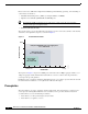
Scalability and Performance Results Table 5 Cisco Router Platform Capabilities Platform Number of Tunnels Shaped at (Mbps) each VoIP Drop %– Jitter-Delay (ms) 871 2 at 2 Mbps 2811 Total Data (pps) pps Total Mbps Total CPU Busy 0.1% 3.3 12.5 12/1200 478 1,047 5.6 64% 2 at 2 Mbps 0% 1 2.4 12/1200 675 1,875 7.3 65% 1841 2 at 4 Mbps 0% 0.5 1.1 24/2400 6,108 8,508 44 50% 1811 2 at 7Mbps 0% 0.2 1.2 42/4200 2,443 6,643 25 56% 2821 2 at 7 Mbps 0% 0.1 1.
Scalability and Performance Results Summary Based on these test results, the Cisco products tested are capable of supporting a branch of one teleworker up to a large branch office of 6000 employees. For larger branch offices, multiple WAN routers would likely be deployed to enhance redundancy, as well as VoIP gateways and potentially direct Internet connectivity, but the inter-enterprise VoIP and data requirements can be supported by an encrypted WAN deployed using Metro Ethernet handoff.
Scalability and Performance Results QoS Devices for Dual-Tier Models In some customer deployments, using a dedicated device to offload the QoS function may be desirable. Table 7 shows how a Catalyst 3750 Metro Ethernet switch can be deployed to provide QoS functions. The results are shown for a headend campus perspective. However, the 3750ME switch can also be deployed at a branch location. Figure 17 shows the typology for the information shown in Table 7.
Scalability and Performance Results The Catalyst 3750 Metro Ethernet switch in this example does not terminate encryption, VoIP, or any other service; it is simply inserted at the headend to provide downstream shaping. VoIP drops, jitter, and delay are reported to demonstrate that these data rates can be sustained without introducing any significant overhead to the existing VoIP stream flowing inside the encrypted DMVPN tunnel.
Case Study Case Study This section provides a case study describing a typical enterprise deployment based on Frame Relay, and demonstrates the configuration changes required at the branch router to connect to an EVPL service at the branch location. It is assumed that the existing branch router is a Cisco ISR 3825, with one of the onboard Gigabit Ethernet interfaces connecting to a Layer 2 switch in the branch office and the second onboard Gigabit Ethernet currently available for use.
Case Study policy-map llq-branch class call-setup bandwidth percent 5 class mission-critical bandwidth percent 22 class voice priority 168 class class-default fair-queue ! ! interface GigabitEthernet0/1.228 description Inside LAN encapsulation dot1Q 228 ip address 10.0.104.1 255.255.255.0 ! ! interface Serial0/1/0 bandwidth 2000 no ip address encapsulation frame-relay load-interval 30 frame-relay traffic-shaping ! interface Serial0/1/0.
Case Study Primary Frame Relay Headend Configuration Both the primary headend and the secondary headend send a default route (0/0) to the branch routers. This is accomplished by redistributing a static route to the default network into the EIGRP process.
Case Study frame-relay cir 486400 frame-relay bc 4864 frame-relay be 0 frame-relay mincir 486400 frame-relay fragment 640 service-policy output llq-branch ! route-map ROUTES_TO_BRANCH permit 10 match ip address ROUTES_TO_BRANCH ! end Secondary Frame Relay Headend Configuration The QoS configuration is not shown; for this, see Primary Frame Relay Headend Configuration, page 47.
Case Study ! ! route-map ROUTES_TO_BRANCH permit 10 match ip address ROUTES_TO_BRANCH ! end Revised Topology and Configuration The revised topology now includes a Metro Ethernet EVPL WAN through the available Gigabit Ethernet port on the branch router, as shown in Figure 19. A new campus router has also been implemented to terminate the Metro Ethernet service on the campus location.
Case Study match ip dscp cs2 class-map match-any REAL_TIME match ip dscp cs5 match ip dscp ef match ip dscp af41 ! policy-map PER_CLASS_2mb class REAL_TIME police 716500 conform-action transmit set cos 5 class GOLD shape average 307200 set cos 3 class SILVER shape average 512000 set cos 2 class class-default shape average 512000 set cos 0 ! interface GigabitEthernet0/0.229 description EVPL VLAN;WAN Interface 229 encapsulation dot1Q 229 ip address 10.0.65.14 255.255.255.
Case Study Sizing the Metro Ethernet Headend As discussed in Scalability and Performance Results, page 40, data is provided to assist the network designer in selecting the appropriate type of headend to support the expected data rate and number of branch routers.The most important data points for sizing a headend are: • Number of branch locations • Data rate in packets per second by branch.
Case Study match ip dscp cs3 match ip dscp cs6 match ip dscp af21 class-map match-any SILVER match ip dscp cs2 class-map match-any REAL_TIME match ip dscp cs5 match ip dscp ef match ip dscp af41 ! ! policy-map PER_CLASS_2mb class REAL_TIME police 716500 conform-action transmit exceed-action transmit violate-action transmit set cos 5 class GOLD shape average 307200 set cos 3 class SILVER shape average 512000 set cos 2 class class-default shape average 512000 set cos 0 ! ! interface GigabitEthernet0/1.
Configuration Examples with a DSL or cable modem deployment to provide backup over broadband services. Because of the embedded encryption adapter support on the ISR series, encryption of both the Metro Ethernet service and the backup links using DSL or cable over the Internet can also easily be deployed. Configuration Examples This section includes sample configurations used in performance and other testing.
Configuration Examples ip tcp adjust-mss 542 duplex auto speed auto no cdp enable service-policy output Shaper ! end For additional information on teleworker configurations, see the Business Ready Teleworker Design Guide at the following URL: http://www.cisco.com/go/srnd. Headend Configuration—7600 SIP-400 - HCBWFQ per VLAN This configuration sample is for the performance testing using a SIP-400 configured with 150 VLANs and using HCBWFQ.
Configuration Examples ! vlan 101,161,163,171,173,181,183,191,193,201,203,211,213 ! vlan 1100 name r1-1-LAN ! vlan 1101 name r1-2-LAN ! vlan 1102 name r1-3-LAN ! ... [and so on] ... ! ! crypto isakmp policy 10 encr aes 256 authentication pre-share group 2 crypto isakmp key bigsecret address 0.0.0.0 0.0.0.
Configuration Examples encapsulation dot1Q 2200 ip address 192.168.0.1 255.255.255.252 crypto engine slot 2/0 outside ! interface GigabitEthernet4/0/0.2201 description r1-2 encapsulation dot1Q 2201 ip address 192.168.1.1 255.255.255.252 crypto engine slot 2/0 outside ! interface GigabitEthernet4/0/0.2202 description r1-3 encapsulation dot1Q 2202 ip address 192.168.2.1 255.255.255.252 crypto engine slot 2/0 outside ! ... [and so on] ...
Configuration Examples set cos 3 class SILVER shape average 768000 set cos 2 class class-default shape average 2480000 set cos 0 ! policy-map INGRESS class REAL_TIME set dscp cs5 class CALL-SETUP set dscp cs5 class STREAMING_VIDEO set dscp cs2 class TRANSACTIONAL_DATA set dscp cs3 class NETWORK_MANAGEMENT set dscp cs3 class BULK_DATA set dscp af21 ! ! vlan internal allocation policy ascending vlan access-log ratelimit 2000 ! vlan 100 name Outside ! vlan 101,161,163,171,173,181,183,191,193,201,203,211,213 !
Configuration Examples crypto dynamic-map dmap-vlan100 10 set transform-set AES_SHA_TUNNEL ! ! ! interface Tunnel0 description Tunnel0 bandwidth 100000 ip address 10.56.0.1 255.255.248.
Configuration Examples Headend Configuration—7600 SIP-600 - Per-Class Shaper per VLAN The following configuration sample is for a Cisco 7600 SIP-600 with each VLAN having a per-class shaper configured. ! hostname he3-7600-1 ! boot-start-marker boot system flash disk0:c7600s72033-adventerprisek9-mz.122-33.SRB1.
Configuration Examples ! vlan 1102 name r1-3-LAN ! ... [and so on] ... ! crypto isakmp policy 10 encr aes 256 authentication pre-share group 2 crypto isakmp key bigsecret address 0.0.0.0 0.0.0.0 crypto isakmp keepalive 10 ! ! crypto ipsec transform-set AES_SHA_TUNNEL esp-aes 256 esp-sha-hmac no crypto ipsec nat-transparency udp-encaps ! crypto ipsec profile vpn-dmvpn set transform-set AES_SHA_TUNNEL ! ! ! interface Tunnel0 description Tunnel0 bandwidth 100000 ip address 10.56.0.1 255.255.248.
Configuration Examples ip address 10.204.0.1 255.252.0.0 no ip redirects load-interval 30 mls qos trust dscp service-policy input INGRESS ! end Branch Configuration—Two VLANs (Per-Class Shaper) The following sample configuration is for a Cisco 3845 using a 25 Mbps aggregate rate on each of two VLANs, supporting two DMVPN tunnels. version 12.
Configuration Examples match ip dscp af11 class-map match-any CALL-SETUP match ip dscp af31 match ip dscp cs3 ! ! policy-map PER_CLASS_25mb class REAL_TIME police 8960000 conform-action transmit exceed-action transmit violate-action transmit set cos 5 class GOLD shape average 3840000 set cos 3 class SILVER shape average 6400000 set cos 2 class class-default shape average 6400000 set cos 0 ! policy-map INGRESS class REAL_TIME set ip dscp cs5 class CALL-SETUP set ip dscp cs5 class STREAMING_VIDEO set ip dscp
Configuration Examples ! ! interface Tunnel0 description Tunnel0 bandwidth 10240 ip address 10.56.1.0 255.255.252.0 ip hold-time eigrp 1 35 ip nhrp authentication test ip nhrp map 10.56.0.1 192.168.31.253 ip nhrp map multicast 192.168.31.253 ip nhrp network-id 105600 ip nhrp holdtime 600 ip nhrp nhs 10.56.0.1 ip nhrp cache non-authoritative ip route-cache flow ip summary-address eigrp 1 10.192.0.0 255.255.255.0 5 load-interval 30 tunnel source 192.168.0.2 tunnel destination 192.168.31.
Configuration Examples description GigabitEthernet0/1 ip address 10.192.0.129 255.255.255.192 secondary ip address 10.192.0.1 255.255.255.128 load-interval 30 duplex full speed 100 media-type rj45 no keepalive service-policy input INGRESS ! ! router eigrp 1 passive-interface GigabitEthernet0/1 network 10.0.0.0 no auto-summary ! ip route 172.26.0.0 255.255.0.0 172.26.180.1 ip route 192.168.0.0 255.255.0.0 192.168.0.1 ip route 192.168.0.0 255.255.0.0 192.168.0.145 ip route 192.168.31.252 255.255.255.255 192.
Troubleshooting class class-default bandwidth percent 5 set cos 0 ! policy-map hqos-policy class r1-1-0000-2200 shape average 1280000 service-policy branch-traffic class r1-2-0001-2201 shape average 1280000 service-policy branch-traffic class r1-3-0002-2202 shape average 1280000 service-policy branch-traffic class r1-4-0003-2203 shape average 1280000 service-policy branch-traffic ! ..... and so on ...
Troubleshooting A cable break is simulated between the CE-1 and 6506-1 devices: 6506-1# *Apr 12 15:36:02 %ETHER_SERVICE-6-EVC_STATUS_CHANGED: status of EVC51 changed to InActive CE-1#show int g0/1.51 GigabitEthernet0/1.51 is down, line protocol is down Hardware is MV96340 Ethernet, address is 0017.94e8.1af1 (bia 0017.94e8.1af1) Internet address is 20.20.20.
Appendix ! crypto logging session ! end Appendix Reference Material • Ethernet service provision requires the right demarcation— http://lw.pennnet.com/Articles/Article_Display.cfm?Section=ARTCL&ARTICLE_ID=229356&V ERSION_NUM=3&p=13 • The long-term architecture for OPT-E-MAN uses Multiprotocol Label Switching/Hierarchical Virtual Private LAN Service (MPLS/H-VPLS)— http://www.att.com/gen/network-disclosure?pid=1803 • Ethernet Services Stage 2— http://www.lightreading.com/document.
Appendix Ethernet Access for Next Generation Metro and Wide Area Networks 68 OL-14760-01