Chapter 3: Cisco NX-OS Software Virtual PortChannel: Fundamental Concepts © 2010 Cisco Systems, Inc. All rights reserved. This document is Cisco Public Information.
Design Guide Contents Virtual PortChannel Technology ................................................................................................................................ 3 vPC Topologies......................................................................................................................................................... 3 Virtual PortChannel Components..............................................................................................................................
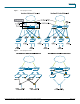
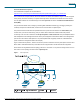
Design Guide Virtual PortChannel Technology Virtual PortChannels (vPCs) allow links that are physically connected to two different Cisco® switches to appear to a third downstream device as coming from a single device and as part of a single port channel. The third device can be a switch, a server, or any other networking device that supports IEEE 802.3ad PortChannels. Cisco NX-OS Software vPCs and Cisco Catalyst® Virtual Switching Systems (VSS) are similar technologies.
Design Guide Figure 1. vPC Topologies A and B Figure 2. vPC Topologies C and D © 2010 Cisco Systems, Inc. All rights reserved. This document is Cisco Public Information.
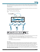
Design Guide Virtual PortChannel Components The fundamental concepts of vPC are described at: http://www.cisco.com/en/US/prod/collateral/switches/ps9441/ps9402/white_paper_c11-516396.html. vPCs consist of two vPC peer switches, which are referred to as Switch1 and Switch2 in Figure 3. Of the vPC peers one is primary and one is secondary. The system formed by Switch1 and Switch2 is referred to as a vPC domain.
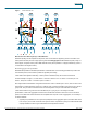
Design Guide Figure 4 illustrates another vPC topology consisting of Cisco Nexus 5000 Series Switches and Cisco Nexus 2000 Series Fabric Extenders (in straight-through mode—that is, each fabric extender is single-attached to a Cisco Nexus 5000 Series Switch). Figure 4 shows devices that are connected to the vPC peer (5k01 and 5k02) with a PortChannel (a vPC): like server 2 (configured for NIC teaming with the 802.3ad option). Server 1 and server 3 connect to orphan ports. Figure 4.
Design Guide Figure 5. Traffic Flows with vPC Dual-Control Plane with Single Layer 2 Node Behavior While still operating with two separate control planes, vPC ensures that the neighboring devices connected in vPCmode perceive the vPC peers as a single spanning-tree and Link Aggregation Control Protocol (LACP) entity. For this to happen, the system has to perform IEEE 802.3ad control plane operations in a slightly modified way (which is not noticeable to the neighbor switch).
Design Guide ● A means of identifying a link aggregation group. For more information please refer to IEEE 802.3ad standard, Amendment to Carrier Sense Multiple Access with Collision Detection (CSMA/CD) Access Method and Physical Layer Specifications— Aggregation of Multiple Link Segments Figure 6. The Components of the System ID In Figure 7, switch 1 announces ports 1and 2 as part of the same aggregation group, and similarly switch 2 announces ports 4 and 5 as part of the same aggregation group.
Design Guide Figure 7. LACP Behavior with Various Wiring Configurations System ID in a vPC System Spanning tree and LACP use the switch MAC address for bridge ID field in the spanning tree bridge protocol data unit (BPDU) and as part of LACP LAGID, respectively. In a single chassis, they use the systemwide MAC address for this purpose. For systems that use vPCs, using the systemwide MAC address would not work because the vPC peers needs to appear as a single entity as exemplified in Figure 7-C.
Design Guide Spanning Tree vPC modifies the way in which spanning tree works on the switch in two ways: ● It makes sure that the peer link is always forwarding. In fact, even if the switch has a direct path to the root, the secondary vPC peer always sees the peer link as the root port towards the primary vPC device.
Design Guide Depending on the severity of the misconfiguration, vPC may either warn the user (Type 2 misconfiguration) or suspend the PortChannel (Type 1 misconfiguration). In the specific case of a VLAN mismatch, only the VLAN that differs between the vPC member ports is going to be suspended on all the vPC PortChannels.
Design Guide Figure 8. vPC VLANs and Orphaned Ports For a VLAN to be on the peer link, it must exist on both vPC peers, and it must appear in the allowed list of the switch port trunk. If either of these conditions is not met, the VLAN isn’t displayed when you enter the command show vpc brief, nor is it a vPC VLAN. A vPC port is a port that is assigned to a vPC channel group. A non-vPC port, also known as orphaned port, is a port that is not part of a vPC.
Design Guide Figure 9. vPC Doesn’t Introduce Duplicate Frames Finally, it is also important to realize that a topology based on PortChannels doesn’t introduce loops, even if the peer link is lost and all the ports are forwarding. Figure 10 explains why. Figure 10 illustrates the worst-case scenario of a vPC dual-active failure when both peer-link and peer-keepalive connectivity is lost.
Design Guide Figure 10. Worst Case of Dual Active Failure 2-Port vPC Versus 4+-Port vPC When you use virtual PortChannels, it is important and useful to categorize two configuration types: ● 4+-port vPCs with two links to each Cisco Nexus switch: On the Cisco Nexus 5000 this configuration consumes one full hardware PortChannel out of each individual switch. For example, if the vPC consists of four ports, each switch locally owns a 2-port PortChannel.
Design Guide Figure 11. 4+ Ports vPCs and 2 Ports vPCs In the case of Unified Fabric (Fibre Channel over Ethernet [FCoE]) deployments, it is important to distinguish 4+ ports Host vPCs from 2-Ports Host vPCs as depicted in Figure 12. In order for FCoE to work, the server adapter needs to see two separate Fibre Channel fabrics. This is only possible when the Converged Network Adapter card has only 1 link per Cisco Nexus 5000 as in the case of server 2 in Figure 12. Figure 12.
Design Guide vPC Member Port Failure If one vPC member port goes down, it is removed from the PortChannel without bringing down the virtual PortChannel entirely. Conversely, the switch on which the port went down will properly unmask this vPC number when sending frames over the peer link (recall the vPC duplicate avoidance technique) in order for the vPC peer to forward the traffic to the remaining vPC member port.
Design Guide Figure 13. Peer-Link Failure As a result of the peer-link failure all traffic in Figure 13 takes the leftmost path via the vPC primary device. This is true both for the client-to-server traffic and the server-to-client traffic. The following show command issued on the secondary vPC peer illustrates the result of the vPC Peer Link failure.
Design Guide tc-nexus5k01# show port channel summary -------------------------------------------------------------------------------Group Port- Type Protocol Member Ports Channel -------------------------------------------------------------------------------51 Po51(SU) Eth LACP Eth2/1(P) Eth2/2(D) The peer keepalive communication ensures that the loss of the peer-link path doesn’t introduce any unwanted flooding, or split subnet scenarios.
Design Guide vPC Complete Dual-Active Failure (Double Failure) In case both the peer link and the peer keepalive link get disconnected, the Cisco Nexus switch does not bring down the vPC, because each Cisco Nexus Switch cannot discriminate between a vPC device reload and a peer-link- plus peer-keepalive failure. This means that each vPC member port keeps advertising the same LACP ID as before the dual-active failure.
Design Guide As you can see, the vPCs are kept up on both systems, and they are recognized as valid PortChannels from the access layer device: 51 Po51(SU) Eth LACP Eth2/1(P) Eth2/2(P) While not intuitive, if both the vPC peer link and Peer Keepalive link fail, it is still possible and desirable to continue forwarding traffic from the access layer to the aggregation layer without drops for existing traffic flows, provided that the Address Resolution Protocol (ARP) tables are already populated on both
Design Guide You can also script this as follows: 7k-1(config)# cli alias name vpcpreempt conf t ; vpc domain ; role priority 32767 ; int ; shut ; no sh * vPC Peer Link A PortChannel connects agg1 with agg2 and carries all access VLANs (defined by the user). This link also carries additional traffic that the user does not need to define, more specifically BPDUs and HSRP hellos, and MAC address synchronization between the vPC peers. This link is called peer link.
Design Guide You should not use the mgmt0 interface for a direct back-to-back connection between Cisco Nexus 7000 systems because you cannot discern which supervisor is active at any given time. You can use it instead on the Cisco Nexus 5000 Series. The mgmt0 interface can be used both for management and for routing the peer keepalive through the out-of-band management network.
Design Guide After a port is defined as part of a PortChannel, any further configurations, such as activation or disablement of bridge assurance or trunking mode are performed under the interface PortChannel configuration mode. Trying to configure spanning tree properties for the physical interface instead of the PortChannel will result in an error message.
Design Guide Alternatively, if the access layer ports are not configured for a channel, the Cisco Nexus 7000 and 5000 Series will operate normally with spanning tree. If the ports on the Cisco Nexus 5000 Series are configured in passive channelgroup mode and the Cisco Nexus 7000 Series ports are not configured for port channeling, the Cisco Nexus 7000 and 5000 Series run spanning tree once more on those ports.
Design Guide HSRP Configuration and Best Practices for vPC The configuration on the primary Cisco Nexus 7000 Series device looks like this: interface vLAN50 no shutdown ip address 10.50.0.251/24 hsrp 50 preempt delay minimum 180 priority 150 timers 1 3 ip 10.50.0.1 The configuration on the secondary Cisco Nexus 7000 Series device looks as follows: interface vLAN50 no shutdown ip address 10.50.0.252/24 hsrp 50 preempt delay minimum 180 priority 130 timers 1 3 ip 10.50.0.
Design Guide Agg2 and forces the VLAN60-to-VLAN50 traffic to Agg1. Agg1 routes from SVI60 to SVI50 and then forwards to Po51 in order to reach n5k. vPC prevents this forwarding behavior as previously explained. Because of this, it is recommended to create a Layer 3 path on the peer link between the routing engines on Agg2 and Agg1 instead of using HSRP tracking. Figure 15.
Design Guide 160-Gbps vPC Between the Cisco Nexus 5000 and Cisco Nexus 7000 Series The Cisco Nexus 5000 Series hardware supports 16-port PortChannels. The Cisco Nexus 7000 Series supports 16port virtual PortChannels with 8 ports per Cisco Nexus 7000 Series. This allows the implementation of the topology shown in Figure 16. Figure 16.
Design Guide Figure 17. Fabric Extender Active-Active Design The main difference is that the vPC configuration is associated with the 10 Gigabit Ethernet ports connecting to the fabric extender (switch port mode fabric extender fabric). As a result, port 100/1/1 in Figure 17 shows both in the nexus5k01 and nexus5k02 configurations.