
User Manual
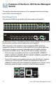
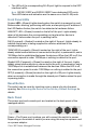
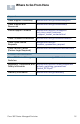
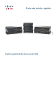
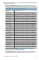
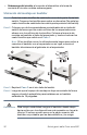
Table Of Contents
- Mounting the Cisco Switch
- Connecting Network Devices
- Configuring the Cisco 300 Series Managed Switch
- Features of the Cisco 300 Series Managed Switch
- Returning the Device to the Factory Default Settings
- Where to Go From Here
- Montaje del switch de Cisco
- Conexión de los dispositivos de red
- Configuración del Cisco 300 Series Managed Switch
- Características del switch administrado Cisco serie 300
- Cómo restablecer la configuración predeterminada de fábrica del dispositivo
- Cómo seguir
- Montage du commutateur Cisco
- Connexion des périphériques réseau
- Configuration du Commutateur administrable Cisco
- Fonctionnalités du commutateur administrable Cisco série 300
- Restauration de la configuration d'origine de l'appareil
- Pour en savoir plus

Cisco 300 Series Managed Switches 13
• The LEDs of the corresponding RJ-45 port light to respond to the SFP
interface traffic.
NOTE SG300-10SFP and SG300-28SFP have dedicated SFP ports.
Their LED status and indication are the same as on the RJ-45 ports.
Front Panel LEDs
System LED—(Green) Lights steady when the switch is powered on, and
flashes when booting, performing self tests, and acquiring an IP address. If
the LED flashes Amber, the switch has detected a hardware failure.
LINK/ACT LED—(Green) Located on the left of the port. Lights steady
when a link between the corresponding port and another device is
detected. Flashes when the port is passing traffic.
PoE (if present)—(Amber) Located on the right of the port. Lights steady to
indicate that power is being supplied to a device attached to the
corresponding port.
100M LED (if present)—(Green) Located on the right of the port. Lights
steady when another device is connected to the port, is powered on, and a
100 Mbps link is established between the devices. When the LED is off, the
connection speed is under 100 Mbps or nothing is cabled to the port.
Gigabit LED (if present)—(Green) Located on the right of the port. Lights
steady when another device is connected to the port, is powered on, and a
1000 Mbps link is established between the devices. When the LED is off,
the connection speed is under 1000 Mbps or nothing is cabled to the port.
SFP (if present)—(Green) Located on the right of a GE port. Lights steady
when a connection is made through the shared port. Flashes when the port
is passing traffic.
Reset Button
The switch can be reset by inserting a pin or paper clip into the reset
opening. See Returning the Device to the Factory Default Settings for
details.
Back Panel
The power port and console port are located on the back panel of the
managed switch.
Power—The Power port is where you will connect the switch to power.
Depending on the model of switch you are using, this may be a power cord
or a power adaptor.