
User Manual
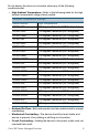
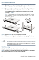
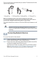
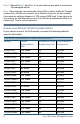
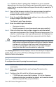
Table Of Contents
- Mounting the Cisco Switch
- Connecting Network Devices
- Configuring the Cisco 300 Series Managed Switch
- Features of the Cisco 300 Series Managed Switch
- Returning the Device to the Factory Default Settings
- Where to Go From Here
- Montaje del switch de Cisco
- Conexión de los dispositivos de red
- Configuración del Cisco 300 Series Managed Switch
- Características del switch administrado Cisco serie 300
- Cómo restablecer la configuración predeterminada de fábrica del dispositivo
- Cómo seguir
- Montage du commutateur Cisco
- Connexion des périphériques réseau
- Configuration du Commutateur administrable Cisco
- Fonctionnalités du commutateur administrable Cisco série 300
- Restauration de la configuration d'origine de l'appareil
- Pour en savoir plus
Cisco 300 Series Managed Switches 5
There is a wall-mount kit packed with your switch. The dimensions for the
mount kit are as follows:
Mount the managed switch to the wall by drilling two pilot holes
3.7 inches (95 mm) apart, attaching the provided anchors and screws to
the wall, then sliding the switch into position on the screws.
The switch should have a minimum of 5 inches (130 mm) of clearance on all
sides.
WARNING Insecure mounting may damage the device or cause injury.
Cisco is not responsible for damages incurred by insecure wall-
mounting.
Connecting Network Devices
To connect the switch to the network:
STEP 1 Connect the Ethernet cable to the Ethernet port of a computer,
printer, network storage, or other network device.
STEP 2 Connect the other end of the network Ethernet cable to one of the
numbered managed switch Ethernet ports.
The Ethernet port light turns green when the connection is active.
Refer to Features of the Cisco 300 Series Managed Switch for
details about the different ports and LEDs on each switch.
1 8 mm/0.4 in 2 22.2 mm/0.9 in 3 6.8 mm/0.3 in 4 17.6 mm/0.7 in
1
2
4
3
196243
2