Quick Start Guide Cisco Small Business 200 Series Smart Switches
Welcome Thank you for choosing the Cisco 200 Series Smart Switch, a Cisco Small Business network communications device. This device is designed to be operational right out-of-the-box as a standard bridge. In the default configuration, it will forward packets between connecting devices after powered up.
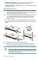
Mechanical Overloading—The device must be level, stable, and secure to prevent it from sliding or shifting out-of-position. Circuit Overloading—Adding the device to the power outlet must not overload that circuit. Rack-Mount Placement STEP 1 Remove the four screws from each side near the front of the switch. Retain the screws for re-installation. (Do not remove the four screws from each side near the back of the switch.
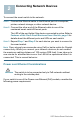
2 Connecting Network Devices To connect the smart switch to the network: STEP 1 Connect the Ethernet cable to the Ethernet port of a computer, printer, network storage, or other network device. STEP 2 Connect the other end of the Ethernet cable to one of the numbered smart switch Ethernet ports. The LED of the port lights if the device connected is active. Refer to Features of the Cisco Small Business Smart Switch, page 9 for details about the different ports and LEDs on each switch.
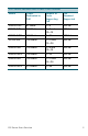
200 Series Switches with Power Over Ethernet Model Power Dedicated to PoE Number of Ports Supporting PoE PoE Standard Supported SG200-10FP 62 Watts 1—8 802.3af SF200-24P 100 Watts 1—6 and 13—18 802.3af SF200-24FP 180 Watts 1—24 802.3af SF200-48P 180 Watts 1—12 and 802.3af 25—36 SG200-26P 100 Watts 1—6 and 13—18 802.3af SG200-26FP 180 Watts 1—24 802.3af SG200-50P 180 Watts 1—12 and 802.3af 25—36 SG200-50FP 375 Watts 200 Series Smart Switches 1—48 802.
CAUTION Consider the following when connecting switches capable of supplying PoE: The PoE models of the switches are PSE (Power Sourcing Equipment) that are capable of supplying DC power to attaching PD (Powered Devices). These devices include VoIP phones, IP cameras, and wireless access points. The PoE switches can detect and supply power to pre-standard legacy PoE Powered Devices.
When the switch is using the factory default IP address, the System LED flashes continuously. When the switch is using a DHCP server-assigned IP address or an administrator has configured a static IP address, the System LED is on solid (DHCP is enabled by default). NOTE If you are managing the switch through a network connection and the switch IP address is changed, either by a DHCP server or manually, your access to the switch will be lost.
CAUTION Make sure that any configuration changes made are saved to the Startup configuration before exiting from the web-based interface by clicking on the Save icon. Exiting before you save your configuration will result in all current changes being lost the next time the switch is rebooted. The Getting Started window displays. You are now ready to configure the switch. Refer to the Cisco 200 Series Smart Switch Administration Guide for further information.
Wrong or conflicting IP address: Make sure that you are using the correct IP address of the switch. You can verify the current IP address of the switch with your network administrator. The System LED provides an indication of where the switch received the IP address, see Section 4 for details. Make sure that no other device is using the same IP address as the switch.
LEDs System LED—(Green) Lights steady when the switch is powered on, and flashes when booting, performing self tests, and acquiring an IP address. If the LED flashes amber, the switch has detected a hardware failure. LINK/ACT LED—(Green) Located on the left of the port. Lights steady when a link between the corresponding port and another device is detected. Flashes when the port is passing traffic. NOTE The System and LINK/ACT LEDs are on each model of the switch.
5 Returning the Device to the Factory Default Settings To use the Reset button to reboot or reset the smart switch, do the following: • To reboot the smart switch, press the Reset button for less than 10 seconds. • To restore the smart switch configuration to the factory default settings: 1. Disconnect the smart switch from the network or disable all DHCP servers on your network. 2. With the power on, press and hold the Reset button for more than 10 seconds.
6 Where to Go From Here Support Cisco Small Business Support Community www.cisco.com/go/smallbizsupport Cisco Small Business Support and Resources www.cisco.com/go/smallbizhelp Cisco Small Business Support Center (SBSC) Contacts www.cisco.com/go/sbsc Cisco Small Business Firmware Downloads www.cisco.com/go/smallbizfirmware Select a link to download firmware for Cisco Small Business Products. No login is required. Product Documentation Cisco Small Business Smart Switches www.cisco.
Americas Headquarters Cisco Systems, Inc. 170 West Tasman Drive San Jose, CA 95134-1706 USA http://www.cisco.com Small Business Support US: 1-866-606-1866 Small Business Support Global Contact Numbers Cisco and the Cisco logo are trademarks or registered trademarks of Cisco and/or its affiliates in the U.S. and other countries. To view a list of Cisco trademarks, go to this URL: www.cisco.com/go/trademarks. Third-party trademarks mentioned are the property of their respective owners.