This product has been discontinued Cisco UCS B440 M2 Blade Server CISCO SYSTEMS 170 WEST TASMAN DR. SAN JOSE, CA, 95134 WWW.CISCO.COM PUBLICATION HISTORY REV B.
CONTENTS OVERVIEW . . . . . . . . . . . . . . . . . . . . . . . . . . . . . . . . . . . . . . . . . . . . . . . 3 DETAILED VIEWS . . . . . . . . . . . . . . . . . . . . . . . . . . . . . . . . . . . . . . . . . . . 4 Chassis Front View . . . . . . . . . . . . . . . . . . . . . . . . . . . . . . . . . . . . . . . . . . . . . . . . . . .4 BASE SERVER STANDARD CAPABILITIES and FEATURES . . . . . . . . . . . . . . . . . 5 CONFIGURING the SERVER . . . . . . . . . . . . . . . . . . . . . . . . . . . . . . . . .
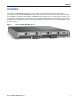
OVERVIEW OVERVIEW The Cisco® UCS B440 M2 Blade Server is a four-socket, full-width blade server that combines the performance of the Intel E7-4800/8800 series processors with up to four small form factor (SFF) hard disk drives (HDDs) or solid-state drives (SSDs), 32 DIMM slots that support up to 1 terabyte (TB) of memory, and two dual-port mezzanine card connections for up to 40 Gbps of redundant I/O throughput. The Cisco UCS B440 M2 server is designed to power the most demanding enterprise applications.
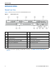
DETAILED VIEWS DETAILED VIEWS Chassis Front View Figure 2 shows the front of the Cisco UCS B440 M2 Blade Server.
BASE SERVER STANDARD CAPABILITIES and FEATURES BASE SERVER STANDARD CAPABILITIES and FEATURES Table 1 lists the capabilities and features of the base server. Details about how to configure the server for a particular feature or capability (for example, number of processors, disk drives, or amount of memory) are provided in CONFIGURING the SERVER on page 7.
BASE SERVER STANDARD CAPABILITIES and FEATURES Table 1 Capabilities and Features (continued) Capability/Feature Description Cisco UCS Diagnostics for Cisco UCS B-Series Blade Servers The Cisco UCS Blade Server Diagnostics tool for Cisco UCS Blade Servers enables you to verify the health of the hardware components on your servers. The diagnostics tool provides a variety of tests to exercise and stress the various hardware subsystems on the Cisco UCS Blade Servers, such as memory and CPU.
CONFIGURING the SERVER CONFIGURING the SERVER Follow these steps to configure the Cisco UCS B440 M2 Server: ■ STEP 1 VERIFY BASE SKU, page 8 ■ STEP 2 CHOOSE CPU(S), page 9 ■ STEP 3 CHOOSE MEMORY, page 10 ■ STEP 4 CHOOSE HARD DISK DRIVES or SOLID-STATE DRIVES, page 14 ■ STEP 6 CHOOSE MEZZANINE OPTION CARD(S), page 16 ■ STEP 7 CHOOSE OPERATING SYSTEM AND VALUE-ADDED SOFTWARE, page 18 ■ STEP 8 CHOOSE OPERATING SYSTEM MEDIA KIT, page 21 ■ STEP 9 CHOOSE SERVICE and SUPPORT LEVEL, page 22 Cisco U
CONFIGURING the SERVER STEP 1 VERIFY BASE SKU Verify the product ID (PID) of the base server as shown in Table 2. Table 2 PID of the Base B440 M2 Server Product ID (PID) B440-BASE-M2 Description UCS B440 M2 Blade Server w/o CPU, memory, HDD, mezzanine The B440-BASE-M2 base server: ■ Does not include CPUs, memory DIMMs, SSDs, HDDs, or mezzanine cards. NOTE: Use the steps on the following pages to configure the server with the components that you want to include.
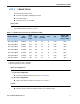
CONFIGURING the SERVER STEP 2 CHOOSE CPU(S) The standard CPU features are: ■ Intel Xeon E7-4800 or E7-8800 series CPUs ■ Intel 7510 chipset ■ Cache size of 18, 24, or 30 MB Choose CPUs The available CPUs are listed in Table 3. Table 3 Available CPUs: Intel Xeon E7-48xx/8867L Family Product ID (PID) Intel Number Clock Freq (GHz) Power (W) Cache Size (MB) Cores QPI Highest DDR3 DIMM Clock Support (MHz) UCS-CPU-E78867L E7-8867L 2.13 105 30 10 6.40 13331 UCS-CPU-E78837 E7-8837 2.
CONFIGURING the SERVER STEP 3 CHOOSE MEMORY The standard memory features are: ■ DIMMs — Maximum memory bandwidth: 800 MHz for E7-4807, 1066 MHz for all other CPUs — Ranks per DIMM: 1, 2, or 4 — Operational voltage: 1.35 V — Registered DIMM (RDIMM) — Mirroring option — Advanced error correcting code (ECC) — Double device data correction (DDDC) NOTE: DDDC support applies to x4 DIMMs only. ■ Each CPU controls four DDR3 channels. Each of the channels controls a matched pair of DIMMs.
CONFIGURING the SERVER Figure 3 B440 M2 Memory Organization Cisco UCS B440 M2 Blade Server 11
CONFIGURING the SERVER Select DIMMs DIMMs are available as two-DIMM kits. Each of the product IDs in Table 4 specifies two DIMMs. Table 4 Available DDR3 DIMMs Product ID (PID) PID Description Voltage Ranks/ DIMM DIMM Pair Kit Options (2 DIMMs per kit) UCS-MR-2X041RX-C 2x4GB DDR3 1333-MHz RDIMM/PC3-10600/1R/x4/1.35v 1.35 V 1 UCS-MR-2X082RX-C 2x8GB DDR3 1333-MHz RDIMM/PC3-10600/2R/x4/1.35v 1.35 V 2 UCS-MR-2x162RX-C 2x16GB DDR3-1333-MHz RDIMM/PC3-10600/2R/x4/1.35v 1.
CONFIGURING the SERVER (2) 4-CPU Configuration ■ 32 DIMMs capacity total ■ Select two or four DIMM kits ( 4 or 8 DIMMs) per CPU. The DIMMs for each CPU will be placed by the factory as shown in Table 6.. Table 6 4-CPU Configuration DIMM Placement Number of DIMMs per CPU DIMM Placement in Numbered/Colored DIMM Slots (see Figure 6 on page 29) 41 (A0, A1) - blue slots; (C0, C1) - white slots 82 (A0, A1) - blue slots; (C0, C1) - white slots (B0, B1) - yellow slots; (D0, D1) - black slots Notes . . .
CONFIGURING the SERVER STEP 4 CHOOSE HARD DISK DRIVES or SOLID-STATE DRIVES The standard disk drive features are: ■ Small form factor HDDs or SSDs ■ Hot-pluggable ■ Sled-mounted Choose Drives The available drives are listed in Table 7.
CONFIGURING the SERVER STEP 5 CHOOSE RAID CONFIGURATION The B440 M2 server integrates the LSI SAS2108 6G SAS RAID controller. Choose RAID Options If desired, choose the RAID 5, 6 upgrade option and battery backup option listed in Table 8. The BBU is an intelligent battery backup unit that protects disk write cache data during a power loss on the RAID controller for up to 72 hours.
CONFIGURING the SERVER STEP 6 CHOOSE MEZZANINE OPTION CARD(S) The standard PCIe card offerings are: ■ Virtual Interface Card (VIC) ■ Converged Network Adapters (CNA) Choose a PCIe Option Card The available PCIe option cards are listed in Table 9.
CONFIGURING the SERVER (2) Supported Combinations Table 10 Supported Adapter Combinations Options Fabric Extender Adapter Slot 1 Compatibility Adapter Slot 2 Ports Reference 2208XP (PIDs UCS-IOM-2208XP, UCS-IOM2208-16FET) or 2204XP (PIDs UCS-IOM-2204XP, UCS-IOM2204-8FET) 2208XP/2204XP None Emulex or QLogic adapter 2 x 10 Gb Figure 8 on page 32 2208XP/2204XP Emulex or QLogic adapter None 2 x 10 Gb Figure 9 on page 33 2208XP/2204XP Emulex Adapter or QLogic adapter1 Emulex Adapter or QLogic adapte
CONFIGURING the SERVER STEP 7 CHOOSE OPERATING SYSTEM AND VALUE-ADDED SOFTWARE Several operating systems and value-added software programs are available. Select as desired from Table 1.
CONFIGURING the SERVER Table 11 OSs and Value-Added Software (for 4-CPU servers) (continued) PID Description Product ID (PID) SLES-SAP-2SUV-3A SLES for SAP Applications (1-2 CPU,Unl Vrt);3yr Support Reqd SLES-SAP-2SUV-5A SLES for SAP Applications (1-2 CPU,Unl Vrt);5yr Support Reqd Red Hat Enterprise Linux RHEL-2S-1G-1A RHEL/2 Socket/1 Guest/1Yr Svcs Required RHEL-2S-1G-3A RHEL/2 Socket/1 Guest/3Yr Svcs Required RHEL-HA-2S-1A RHEL Option/High-Availability/2 Socket/1Yr Svcs Required RHEL-HA-2S-3A
CONFIGURING the SERVER Table 11 OSs and Value-Added Software (for 4-CPU servers) (continued) PID Description Product ID (PID) VMW-VS5-STD-3A VMware vSphere 5 Standard for 1 Processor, 3 Year, Support Rqd VMW-VS5-STD-4A VMware vSphere 5 Standard for 1 Processor, 4 Year, Support Rqd VMW-VS5-STD-5A VMware vSphere 5 Standard for 1 Processor, 5 Year, Support Rqd VMW-VS5-ENT-1A VMware vSphere 5 Enterprise for 1 Processor, 1 Year Support Rqd VMW-VS5-ENT-2A VMware vSphere 5 Enterprise for 1 CPU, 2 Yr Su
CONFIGURING the SERVER STEP 8 CHOOSE OPERATING SYSTEM MEDIA KIT Choose the optional operating system media listed in Table 12.
CONFIGURING the SERVER STEP 9 CHOOSE SERVICE and SUPPORT LEVEL A variety of service options are available, as described in this section. Unified Computing Warranty, No Contract If you have noncritical implementations and choose to have no service contract, the following coverage is supplied: ■ Three-year parts coverage. ■ Next business day (NBD) onsite parts replacement eight hours a day, five days a week. ■ 90-day software warranty on media.
CONFIGURING the SERVER SMARTnet for UCS Hardware Only Service For faster parts replacement than is provided with the standard Cisco Unified Computing System warranty, Cisco offers the Cisco SMARTnet for UCS Hardware Only Service. You can choose from two levels of advanced onsite parts replacement coverage in as little as four hours. SMARTnet for UCS Hardware Only Service provides remote access any time to Cisco support professionals who can determine if a return materials authorization (RMA) is required.
CONFIGURING the SERVER See Table 15.
CONFIGURING the SERVER You can choose a service listed in Table 17.
CONFIGURING the SERVER Table 18 Drive Retention Service Options (continued) Service Description Service Program Name SMARTnet for UCS HW ONLY+Drive Retention UCS HW+DR Service Level GSP Service Level Product ID (PID) UCWD7 24x7x4 Onsite CON-UCWD7-B440M2 UCWD5 8x5xNBD Onsite CON-UCWD5-B440M2 For more service and support information, see the following URL: http://www.cisco.com/en/US/services/ps2961/ps10312/Unified_Computing_Services_Overview.
CONFIGURING the SERVER ORDER OPTIONAL KVM CABLE The KVM cable provides a connection into the server, providing a DB9 serial connector, a VGA connector for a monitor, and dual USB 2.0 ports for a keyboard and mouse. With this cable, you can create a direct connection to the operating system and the BIOS running on the server. The KVM cable ordering information is listed in Table 19.
SUPPLEMENTAL MATERIAL SUPPLEMENTAL MATERIAL Motherboard A top view of the B440 M2 motherboard is shown in Figure 5.
SUPPLEMENTAL MATERIAL DIMM and CPU Layout Each CPU controls four memory channels, as follows (refer to Figure 3 on page 11): ■ Channels A, B, C, and D — Bank 0: A0 (blue DIMM slot), C0 (white DIMM slot), B0 (yellow DIMM slot), D0 (black DIMM slot) — Bank 1: A1 (blue DIMM slot), C1 (white DIMM slot), B1 (yellow DIMM slot), D1 (black DIMM slot) The DIMM and CPU physical layout is shown in Figure 6. Each CPU is located to the right of the DIMMs it controls.
SUPPLEMENTAL MATERIAL 30 — Unevenly populating DIMMs between CPUs — Populating channels with an odd number of total ranks (for example, mixing single-rank and dual-rank DIMMs) — Using anything other than 4 or 8 DIMMs per CPU properly placed in the system Cisco UCS B440 M2 Blade Server
SUPPLEMENTAL MATERIAL Network Connectivity This section explains how the UCS B440 M2 server connects to Fabric Interconnects using the network I/O adapters in the UCS B440 M2 blade server and the Fabric Extender modules in the UCS 5108 blade server chassis. The UCS B440 M2 server plugs into the front of the UCS 5108 blade server chassis. The Fabric Extender modules plug into the back of the UCS 5108 series blade server chassis. A midplane connects the UCS B440 M2 blade server to the Fabric Extenders.
SUPPLEMENTAL MATERIAL The network adapter options are: ■ VIC 1280 Mezzanine adapter. This adapter plugs into either mezzanine slot and is capable of 4x10Gb ports in the UCS B440 M2 server, depending on the Fabric Extender chosen (see Table 10 on page 17) and 256 PCIe devices. ■ Emulex or QLogic I/O adapter. These adapters plug into either mezzanine slot and are capable of 2x10Gb ports in the UCS B440 M2 server, depending on the Fabric Extender chosen.
SUPPLEMENTAL MATERIAL In Figure 8, there is no adapter installed in adapter slot 2. In this case, an Emulex or QLogic I/O adapter is installed in adapter 1 slot. Ports A and B of the mezzanine adapter connect to the Fabric Extenders, providing 10 Gbps per port, for a total of 20 Gbps throughput.
SUPPLEMENTAL MATERIAL In Figure 11, two ports from the VIC 1280 in slot 1 are channeled to Fabric Extender A and two are channeled to Fabric Extender B. The result is 20 Gbps of bandwidth to each Fabric Extender. There is no adapter installed in adapter 2 slot. Figure 11 VIC 1280 to UCS 2204/2208XP Fabric Extender (no adapter in slot 2) In Figure 12, two ports from the VIC 1280 in slot 2 are channeled to Fabric Extender A and two are channeled to Fabric Extender B.
SUPPLEMENTAL MATERIAL In Figure 13, there are two VIC 1280 adapters installed. One port from each VIC 1280 is connected to Fabric Extender A and one is connected to Fabric Extender B. The result is 20 Gbps of bandwidth to each Fabric Extender. Figure 13 Two VIC 1280s to UCS 2204/2208XP Fabric Extender In Figure 14, one port from the VIC 1280 in slot 1 is connected to Fabric Extender A and one is connected to Fabric Extender B.
SUPPLEMENTAL MATERIAL In Figure 15, one port from the VIC 1280 in slot 2 is connected to Fabric Extender A and one is connected to Fabric Extender B. Likewise, one port from the QLogic or Emulex adapter in slot 1 is also connected to each Fabric Extender. The result is 20 Gbps of bandwidth to each Fabric Extender.
SUPPLEMENTAL MATERIAL Figure 16 Emulex or QLogic I/O Adapter to UCS 2104XP Fabric Extender (no slot 1 adapter) In Figure 17, there is no adapter installed in adapter slot 2. In this case, an Emulex or QLogic I/O adapter is installed in adapter 1 slot. Ports A and B of the mezzanine adapter connect to the Fabric Extenders, providing 10 Gbps per port, for a total of 20 Gbps throughput.
SUPPLEMENTAL MATERIAL In Figure 18, either two identical Emulex or two identical QLogic adapters are installed (do not mix Emulex and QLogic adapters). Port A of each adapter connects to the Fabric Extenders, providing 10 Gbps per port, for a total of 20 Gbps throughput. Figure 18 Two Emulex or QLogic I/O Adapters to UCS 2104XP Fabric Extender In Figure 19, one port from the VIC 1280 in slot 1 is connected to Fabric Extender A and one is conected to Fabric Extender B.
SUPPLEMENTAL MATERIAL In Figure 20, one port from the VIC 1280 in slot 2 is connected to Fabric Extender A and one is connected to Fabric Extender B. The result is 10 Gbps of bandwidth to each Fabric Extender. There is no adapter installed in adapter 1 slot. Figure 20 VIC 1280 to UCS 2104P Fabric Extender (no adapter in slot 1) In Figure 21, there are two VIC 1280 adapters installed.
SUPPLEMENTAL MATERIAL In Figure 22, one port from the VIC 1280 in slot 1 is connected to Fabric Extender B. Likewise, one port from the QLogic or Emulex adapter in slot 2 is connected to Fabric Extender A. The result is 10 Gbps of bandwidth to each Fabric Extender. Figure 22 VIC 1280 and Emulex or QLogic adapter to UCS 2104XP Fabric Extender In Figure 23, one port from the VIC 1280 in slot 2 is connected to Fabric Extender A.
TECHNICAL SPECIFICATIONS TECHNICAL SPECIFICATIONS Dimensions and Weight Table 20 UCS B440 M2 Dimensions and Weight1 Parameter Value Height 1.95 in. (50 mm) Width 16.50 in.(419.1 mm) Depth 24.4 in. (620 mm) Weight 34.5 lbs (15.65 kg)* Notes . . . 1. The system weight given here is an estimate for a fully configured system and will vary depending on the number of CPUs, memory DIMMs, and other optional items.
TECHNICAL SPECIFICATIONS 42 Cisco UCS B440 M2 Blade Server