
Data Sheet


Cisco UCS B440 M2 Blade Server
SUPPLEMENTAL MATERIAL
29
DIMM and CPU Layout
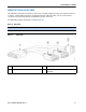
Each CPU controls four memory channels, as follows (refer to Figure 3 on page 11):
■ Channels A, B, C, and D
— Bank 0: A0 (blue DIMM slot), C0 (white DIMM slot), B0 (yellow DIMM slot), D0 (black
DIMM slot)
— Bank 1: A1 (blue DIMM slot), C1 (white DIMM slot), B1 (yellow DIMM slot), D1 (black
DIMM slot)
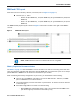
The DIMM and CPU physical layout is shown in Figure 6. Each CPU is located to the right of the DIMMs it
controls.
Figure 6 DIMM and CPU Layout
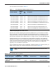
Memory Population Recommendations
See Table 5 on page 12. Note that DIMMs in slots of the same color must be electrically paired with each
other, and should be populated with identically matched DIMMs that were ordered as a pair. Do not swap a
paired DIMM with a DIMM that is not identical in manufacturer part number.
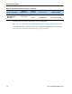
When considering the memory configuration of your server, you should observe the following:
■ There is only one DIMM slot (one bank) in each of the DDR channels. Therefore, all DIMM
pairs in a B440 M2 server must be identical.
■ Your selected CPU(s) can have some effect on performance. All CPUs in the server must be
of the same type.
■ Performance degradation can result from the following:
— Mixing DIMM sizes and densities within a pair is not allowed and both DIMMs in the
pair will be logically removed from the memory array
NOTE: DIMMs installed in slots for an absent CPU are not recognized.