
User guide

36 Fast Ethernet Interface Processor (FEIP) Installation and Configuration
Configuring the Fast Ethernet Interfaces*
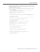
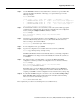
To determine which type of interfaces are installed on an FEIP in your system, use the
show diag slot command. Specific interface information is displayed, as shown in the following
example of an FEIP in interface processor slot 2:
Router# show diag 2
Slot 2:
Physical slot 2, ~physical slot 0xD, logical slot 2, CBus 0
Microcode Status 0x4
Master Enable, LED, WCS Loaded
Board is analyzed
Pending I/O Status: None
EEPROM format version 1
FEIP controller, HW rev 2.4, board revision D0
Serial number: 03700746 Part number: 73-1684-03
Test history: 0x00 RMA number: 00-00-00
Flags: cisco 7000 board; 7500 compatible
EEPROM contents (hex):
0x20: 01 20 02 04 00 38 78 0A 49 06 94 03 00 00 00 00
0x30: 68 00 00 03 00 00 00 00 00 00 00 00 00 00 00 00
Slot database information:
Flags: 0x4 Insertion time: 0x9B8 (00:17:10 ago)
Controller Memory Size: 8 MBytes DRAM, 1024 KBytes SRAM
PA Bay 0 Information:
Fast-Ethernet PA, 1 ports, 100BaseTX-ISL
EEPROM format version 1\
HW rev 1.0, Board revision A0
Serial number: 04622911 Part number: 73-1688-03
PA Bay 1 Information:
Fast-Ethernet PA, 1 ports, 100BaseTX-ISL
EEPROM format version 1
HW rev 1.0, Board revision A0
Serial number: 03540609 Part number: 73-1688-03
In the preceding example, the two interfaces on the FEIP are clearly marked 100BaseTX.
For additional Fast Ethernet command descriptions and examples, refer to the publications listed in
the section “If You Need More Information” on page 2.