Doc. No. 78-4200-03 Second-Generation Fast Ethernet Interface Processor (FEIP2) Installation and Configuration Product Numbers: CX-FEIP2-2TX= and CX-FEIP2-2FX= This configuration note is a standalone publication that provides instructions for installing and configuring the second-generation Fast Ethernet Interface Processor (FEIP2) in all Cisco 7500 series routers, and in Cisco 7000 series routers using the 7000 Series Route Switch Processor (RSP7000) and 7000 Series Chassis Interface (RSP7000CI).
Document Contents Document Contents This configuration note includes the following sections: • • • • • • • If You Need More Information Installation Prerequisites, page 3 What Is the FEIP2?, page 16 FEIP2 Installation, page 23 Configuring the Fast Ethernet Interfaces, page 30 Upgrading FEIP2 Microcode, page 39 Cisco Connection Online, page 42 If You Need More Information The Cisco IOS software running your router contains extensive features and functionality.
Installation Prerequisites — Cisco Customer Service at 800 553-6387 or 408 526-7208. Customer Service hours are 5:00 a.m. to 6:00 p.m. Pacific time, Monday through Friday (excluding company holidays). You can also send e-mail to cs-rep@cisco.com. — The Cisco Information Packet that shipped with your router.
Installation Prerequisites List of Parts and Tools You need the following tools and parts to install or upgrade an FEIP2. If you need additional equipment, contact a service representative for ordering information. • CX-FEIP2-2TX(=) or CX-FEIP2-2FX(=), and at least one available interface processor slot in your Cisco 7000 series or Cisco 7500 series router (For specific compatibility requirements, refer to the section “Software and Hardware Prerequisites” on page 3.
Installation Prerequisites Varoitus Tämä varoitusmerkki merkitsee vaaraa. Olet tilanteessa, joka voi johtaa ruumiinvammaan. Ennen kuin työskentelet minkään laitteiston parissa, ota selvää sähkökytkentöihin liittyvistä vaaroista ja tavanomaisista onnettomuuksien ehkäisykeinoista. Tässä julkaisussa esiintyvien varoitusten käännökset löydät laitteen mukana olevasta Regulatory Compliance and Safety Information -kirjasesta (määräysten noudattaminen ja tietoa turvallisuudesta).
Installation Prerequisites Electrical Equipment Guidelines Follow these basic guidelines when working with any electrical equipment: • Before beginning any procedures requiring access to the chassis interior, locate the emergency power-off switch for the room in which you are working. • • • • • Disconnect all power and external cables before moving a chassis Do not work alone when potentially hazardous conditions exist. Never assume that power has been disconnected from a circuit; always check.
Installation Prerequisites Guidelines for Interface Processor Installation and Removal This section describes mechanical functions of system components, emphasizes the importance of following correct procedures to avoid unnecessary board failures, and is for background only; specific procedures follow in the section “FEIP2 Installation” on page 23. You can remove and replace interface processors while the system is operating; you do not need to notify the software or reset the system power.
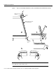
Installation Prerequisites Figure 1 Ejector Levers/Captive Installation Screws on the FEIP2 (Horizontal Orientation Shown) Interface processor card slot Ejector lever Interface processor card carrier guide (black) a b Captive installation screw H1984 c Note The FEIP2 is oriented horizontally in the Cisco 7010 and Cisco 7505 and vertically in the Cisco 7000, Cisco 7507, and Cisco 7513.
Installation Prerequisites Microcode Overview The FEIP2 microcode (firmware) is an image that provides card-specific software instructions. A programmable read-only memory (PROM) device on the FEIP2 contains a default microcode boot image that assists the system in finding and loading the microcode image from the Cisco IOS software bundle or Flash memory.
Installation Prerequisites IEEE 802.
Installation Prerequisites What Is the Cisco 7000 Series? The Cisco 7000 series consists of the Cisco 7000 and Cisco 7010 routers. The FEIP2 operates in the Cisco 7000 series routers if these routers have the 7000 Series Route Switch Processor (RSP7000) and 7000 Series Chassis Interface (RSP7000CI) installed. (For software and hardware requirements, refer to the section “Software and Hardware Prerequisites” on page 3.
Installation Prerequisites In the 5-slot Cisco 7010, slot 3 is reserved for the RSP7000, which contains the system processor and performs packet switching functions, and slot 4 is reserved for the RSP7000CI, which contains all of the environmental monitoring functions for the Cisco 7010. The remaining three slots (slots 0 through 2) are for interface processors including the FEIP2.
Installation Prerequisites What Is the Cisco 7500 Series? The Cisco 7500 series includes the Cisco 7505, Cisco 7507, and Cisco 7513 routers. The FEIP2 operates in the Cisco 7500 series routers. (For software and hardware requirements, refer to the section “Software and Hardware Prerequisites” on page 3.
Installation Prerequisites Figure 5 shows the interface processor end of the Cisco 7507 router. In the 7-slot Cisco 7507, up to two slots (2 and 3) are reserved for the Route Switch Processor (RSP2 or RSP4), which contains the system processor and performs packet switching functions. Slots 0 and 1 and 4 through 6 are for interface processors including the FEIP2.
Installation Prerequisites Figure 6 shows the interface processor end of the Cisco 7513 router. In the Cisco 7513, up to two slots (6 and 7) are reserved for the second generation Route Switch Processor (RSP2 or RSP4), which contains the system processor and performs packet switching functions. Slots 0 through 5 and 8 through 12 are for interface processors including the FEIP2.
What Is the FEIP2? What Is the FEIP2? The FEIP2 is a dual-port, fixed configuration interface processor that provides two, 100-Mbps, IEEE 802.3u Fast Ethernet (FE) interface interfaces. The FEIP2 is available in the following fixed configurations: • FEIP2-2TX(=)—FEIP2 with two, 100BASE-TX FE interfaces (See Figure 7.
What Is the FEIP2? • FEIP2-2FX(=)—FEIP2 with two, 100BASE-FX FE interfaces (See Figure 8.
What Is the FEIP2? Note Each of the FEIP2-2FX’s two 100BASE-FX interfaces uses the MII connector like the FEIP2-2TX, but the FEIP2-2FX has an SC-type fiber-optic connector in place of the RJ-45 connector. Either the MII LED or the RJ-45 (or FIBER) LED should be on at any one time; never both. Caution To prevent system problems, do not simultaneously connect cables to the RJ-45 (or SC) and MII receptacles on a single FEIP2 FE interface.
What Is the FEIP2? FEIP2 Receptacles, Cables, and Pinouts The two interface receptacles on each Fast Ethernet interface are a single MII, 40-pin, D-shell type receptacle, and a single RJ-45 receptacle (or SC-type for FEIP2-2FX optical-fiber connections). (See the FEIP2-2TX in Figure 10 and the FEIP2-2FX in Figure 11.) You can use either one receptacle or the other; only one receptacle can be used at one time. Each connection supports IEEE 802.
What Is the FEIP2? Warning The ports labeled “Ethernet,” “10BaseT,” “Token Ring,” “Console,” and “AUX” are safety extra-low voltage (SELV) circuits. SELV circuits should only be connected to other SELV circuits. Because the BRI circuits are treated like telephone-network voltage, avoid connecting the SELV circuit to the telephone network voltage (TNV) circuits. Table 4 lists the pinouts and signals for the FEIP2-2TX’s RJ-45 connectors.
What Is the FEIP2? Figure 15 shows the duplex SC connector (one required for both transmit and receive), and Figure 16 shows the simplex SC connector (two required, one for each transmit and receive) used for 100BASE-FX optical-fiber connections on the FEIP2-2FX. These multimode, SC-type, optical-fiber cables are commercially available; they are not available from Cisco Systems.
What Is the FEIP2? Table 5 lists the MII connector pinout and signals. MII cables are available commercially; they are not available from Cisco Systems. Table 5 refers to MII cables used between the MII connector on the FEIP2 and an appropriate transceiver. The connection between this transceiver and your network can be Category 3, 4, or 5, 150-ohm UTP or STP, or multimode optical fiber.
FEIP2 Installation FEIP2 Installation The following sections describe the procedures for removing or installing an FEIP2 in the Cisco 7000 series or Cisco 7500 series routers. The functionality is the same for each router model; therefore, the term the chassis is used except where specific model issues arise. The online insertion and removal function allows you to install and remove an FEIP2 without first shutting down the system; however, you must follow the instructions carefully.
FEIP2 Installation Removing an FEIP2 You need not shut down the interface or the system power when removing an FEIP2 or interface processor. Note In Cisco 7507 or Cisco 7513 systems, online insertion and removal of any interface processor in either CyBus might cause the slave RSP2 to reboot with a bus error or a processor memory parity error. The master RSP will recover from this event and issue a “cBus Complex Restart” message.
FEIP2 Installation To remove an FEIP2 or interface processor, follow these steps: Step 1 Attach an ESD-preventive wrist strap between you and any unpainted chassis surface. Step 2 If you are replacing a failed FEIP2, disconnect all cables from the FEIP2 ports; however, if you are only moving an FEIP2 to another slot, this step is not necessary. Step 3 Use a screwdriver to loosen the captive installation screws at both ends of the board. (See Figure 1.
FEIP2 Installation Follow these steps to install an FEIP2: Step 1 Ensure that a console terminal is connected to the console port (on the RSP or RSP7000) and that your console is turned ON. Step 2 Hold the FEIP2 handle with one hand and place your other hand under the carrier to support the FEIP2 and guide it into the slot. (See Figure 18.) Avoid touching the card or any connector pins. Caution To prevent ESD damage, handle interface processors by the handles and carrier edges only.
FEIP2 Installation Connect RJ-45, SC (FEIP2-2FX), or MII cables as follows: If you have MII connections, attach an MII cable directly to the MII port on the FEIP2 or attach a 100BASE-T transceiver, with the media appropriate to your application, to the MII port on the FEIP2. (See Figure 19 for FEIP2-2TX or Figure 20 for FEIP2-2FX.
FEIP2 Installation MII cable ER H9785 K II FIB M LIN ER FAST ETHERNET 0 II M FAST ETHERNET 0 LIN K Connecting MII or SC Cables (FEIP2-2FX Shown, Horizontal Orientation) FIB Figure 20 or Simplex (2) To repeater To transceiver, repeater, or DTE Step 2 Duplex (1) To repeater For the 100BASE-TX RJ-45 connections, attach the ferrite bead to the RJ-45 cable (at either end), as shown in Figure 21.
FEIP2 Installation Using LEDs to Check FEIP2 Status The FEIP2 has four status LEDs on its faceplate that indicate status on each FE port. (See Figure 22.) LEDs (Partial Faceplate View of FEIP2) H2941 Figure 22 After you connect cables, observe the LED states and the console display as the router initializes. When the system has reinitialized all interfaces, the enabled LED on the FEIP2 should go on. (For complete descriptions of the FEIP2 LEDs, refer to the section “FEIP2 LEDs” on page 18.
Configuring the Fast Ethernet Interfaces Step 4 If an enabled LED still fails to go on, remove the FEIP2 and try installing it in another available interface processor slot. If the enabled LED goes on when the FEIP2 is installed in the new slot, suspect a failed backplane port in the original interface processor slot.
Configuring the Fast Ethernet Interfaces Selecting Interface Processor Slot, Fast Ethernet Interface, and Interface Port Numbers This section describes how to identify interface processor slot, FE interface, and interface port numbers. Note Although the interface processor slots in the Cisco 7000, Cisco 7507, and Cisco 7513 are vertically oriented and those in the Cisco 7010 and Cisco 7505 are horizontally oriented, all models use the same method for slot and port numbering.
Configuring the Fast Ethernet Interfaces FE Interface Port Address Example (Cisco 7505 with FEIP2-2TX Shown) EN AB LE CO NS OL E AU X. HA LT ROUTE SWITCH PROCESSOR RE SE T CP U EJ EC T Port address 3/1/0 (100Base-TX interface) SL SLO OT T 0 1 NO RM AL Port address 3/0/0 (100Base-TX interface) Slot 3 EN AB LE Figure 23 Slot 2 Slot 1 Interface processor slots H9786 Slot 0 Note: The MII and RJ-45 interface ports on each port adapter are both numbered as interface port 0.
Configuring the Fast Ethernet Interfaces Step 4 Add any additional configuration subcommands required to enable routing protocols and set the interface characteristics. Step 5 Change the shutdown state to up and enable the interface as follows: Router(config-int)# no shutdown Step 6 Configure additional FE interfaces as required. Step 7 When you have included all of the configuration subcommands to complete the configuration, press Ctrl-Z to exit configuration mode.
Configuring the Fast Ethernet Interfaces Using the show interfaces fastethernet command, you can see that the 3/0/0 FE interface is now configured for full-duplex operation: Router# sh int fa 3/0/0 FastEthernet 3/0/0 is administratively up, line protocol is up (display text omitted) Encapsulation ARPA, loopback not set, keepalive not set, fdx, 100BaseTX To return the interface to half-duplex operation, use the no full-duplex configuration command, as follows: Router# config t Enter configuration commands,
Configuring the Fast Ethernet Interfaces Checking the Configuration After configuring the new interface, use the show commands to display the status of the new interface or all interfaces and the ping command to check connectivity. Using show Commands to Verify the FEIP2 Status The following steps use show commands to verify that the new interfaces are configured and operating correctly. Step 1 Use the show version command to display the system hardware configuration.
Configuring the Fast Ethernet Interfaces With the show interfaces [type slot/adapter/port] command, use arguments such as the interface type (fastethernet, and so forth) and the port number (slot/port) to display information about a specific interface only, as in the following example of the show interfaces fastethernet command, which shows information specific to the first FE interface on an FEIP2 in interface processor slot 2: Router# show interfaces fastethernet 2/0/0 FastEthernet2/0/0 is administrative
Configuring the Fast Ethernet Interfaces The show version (or show hardware) command displays the configuration of the system hardware (the number of each interface processor type installed), the software version, the names and sources of configuration files, and the boot images. Following is an example of the show version command used with a Cisco 7500 series system: Router# show version Cisco Internetwork Operating System Software IOS (tm) GS Software (RSP-JV-M), Released Version 11.
Configuring the Fast Ethernet Interfaces To determine which type of interfaces are installed on an FEIP2 in your system, use the show diag slot command. Specific interface information is displayed, as shown in the following example of an FEIP2 in interface processor slot 2: Router# show diag 2 Slot 2: Physical slot 2, ~physical slot 0xD, logical slot 2, CBus 0 Microcode Status 0x4 Master Enable, LED, WCS Loaded Board is analyzed Pending I/O Status: None EEPROM format version 1 FEIP2 controller, HW rev 2.
Upgrading FEIP2 Microcode Following is an example of a successful ping command to a remote server with the address 1.1.1.10: Router# ping 1.1.1.10 Type escape sequence to abort. Sending 5, 100-byte ICMP Echoes to 1.1.1.10, timeout is 2 seconds: !!!!! Success rate is 100 percent (5/5), round-trip min/avg/max = 1/15/64 ms Router# If the connection fails, verify that you have the correct IP address for the server and that the server is active (powered on), and repeat the ping command.
Upgrading FEIP2 Microcode Caution Before you copy a file to system Flash memory, be sure there is ample space available in Flash memory. Compare the size of the file you want to copy to the amount of available Flash memory shown. If the space available is less than the space required by the file you want to copy, the copy process continues, but the entire file is not be copied into Flash memory.
Upgrading FEIP2 Microcode Step 5 To ensure that the new microcode is used when you reboot the system, add the appropriate commands to the configuration file. To modify the configuration file, enter configuration mode by issuing the configure terminal command as follows: Router# config t Enter configuration commands, one per line. Router(config)# Step 6 End with CNTL/Z.
Cisco Connection Online Cisco Connection Online Cisco Connection Online (CCO) is Cisco Systems’ primary, real-time support channel. Maintenance customers and partners can self-register on CCO to obtain additional information and services. Available 24 hours a day, 7 days a week, CCO provides a wealth of standard and value-added services to Cisco’s customers and business partners.