
Specifications

22 Second-Generation Fast Ethernet Interface Processor (FEIP2) Installation and Configuration
What Is the FEIP2?
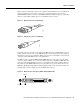
Table 5 lists the MII connector pinout and signals. MII cables are available commercially; they are
not available from Cisco Systems. Table 5 refers to MII cables used between the MII connector on
the FEIP2 and an appropriate transceiver. The connection between this transceiver and your network
can be Category 3, 4, or 5, 150-ohm UTP or STP, or multimode optical fiber.
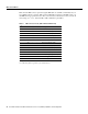
Table 5 MII Connector Pinout (FEIP2-2FX and FEIP2-2TX)
1. Any pins not indicated are not used.
2. Tx_CLK and Rx_CLK are generated by the external transceiver.
Pin
1
In Out In/Out Description
14–17 – Yes – Transmit Data (TxD)
12 Yes – – Transmit Clock (Tx_CLK)
2
11 – Yes – Transmit Error (Tx_ER)
13 – Yes – Transmit Enable (Tx_EN)
3 – Yes – MII Data Clock (MDC)
4–7 Yes – – Receive Data (RxD)
9 Yes – – Receive Clock (Rx_CLK)
10 Yes – – Receive Error (Rx_ER)
8 Yes – – Receive Data Valid (Rx_DV)
18 Yes – – Collision (COL)
19 Yes – – Carrier Sense (CRS)
2 – – Yes MII Data Input/Output (MDIO)
22–39 – – – Common (ground)
1, 20, 21, 40 – – – +5.0 volts (V)