MR78-HW/GR62-HW Installation Guide The Cisco Meraki MR78-HW/GR62-HW is a dual-band enterprise class 802.11ax cloud-managed access point.
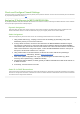
• Mount cradle including built-in level tool 2
• Mount Kit ◦ Wall screws and wall screw anchors Grounding cable RJ45 Cable Meraki GO/GA-PWR-12W-US/UK/AU/EU UMEC & MA-PWR-30WAC 3
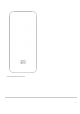
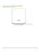
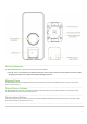
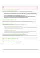
Understanding the MR78-HW/GR62-HW Your Meraki MR78-HW/GR62-HW has the following features: 4
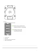
The mount cradle has the following features: Security Features The MR78-HW/GR62-HW allows for physically securing the access point after installation: 1. Security screw – The accessory kit includes screws that can be used to secure the access point to the mount cradle. Engaging the security screw prevents accidental dislodging and theft. Ethernet Ports The MR78-HW/GR62-HW features a Gigabit Ethernet RJ45 port that accepts 802.3at and 802.3af power (labeled “Eth0, PoE”).
LED Indicators and Run Dark Mode Your MR78-HW/GR62-HW is equipped with a multi-color LED light on the front of the unit to convey information about system functionality and performance: • Orange - AP is booting (permanent Orange suggests hardware issue) • Rainbow - AP is initializing/scanning • Blinking Blue - AP is upgrading • Green - AP in Gateway mode with no clients • Blue - AP in Gateway mode with clients • Blinking Orange - AP can't find uplink NOTE: Blinking Green LED indicates that the device is in
Check and Configure Firewall Settings If a firewall is in place, it must allow outgoing connections on particular ports to particular IP addresses. The most current list of outbound ports and IP addresses for your particular organization can be found here. Assigning IP Addresses to MR78-HW/GR62-HWs All gateway MR78-HW/GR62-HWs (MR78-HW/GR62-HWs with Ethernet connections to the LAN) must be assigned routable IP addresses. These IP addresses can be dynamically assigned via DHCP or statically assigned.
Collect Tools You will need the following tools to perform an installation: Collect Additional Hardware for Installation You will need the following hardware to perform an installation: Installation Instructions 8
Choose Your Mounting Location A good mounting location is important to getting the best performance out of your MR78-HW/GR62-HW access point. Keep the following in mind: 1. The device should have unobstructed line of sight to most coverage areas. For example, if installing in an office filled with workspaces divided by mid-height cubicle walls, installing on the ceiling or high on a wall would be ideal. 2. Power over Ethernet supports a maximum cable length of 300 ft (100 m). 3.
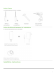
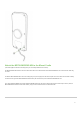
Attach the MR78-HW/GR62-HW to the Mount Cradle (This section applies to wall and/or solid ceiling where you have already installed the mount cradle.) The MR78-HW/GR62-HW attaches to the mount cradle with two tabs on the cradle that insert into the MR78-HW/GR62-HW, and is secured to the cradle using one screw. To attach the MR78-HW/GR62-HW to the mount cradle properly, line up the top edge of the AP with the top tab of the mount cradle.
To release the MR78-HW/GR62-HW from the mount cradle, first remove the security screw that secures the MR78-HW/GR62-HW to the cradle’s bottom tab. While holding the MR78-HW/GR62-HW with one hand, press the cradle’s bottom tab upwards, releasing the MR78-HW/GR62-HW from the bottom of the cradle. Then remove the MR78-HW/GR62-HW from the cradle’s top tab.
Secure the MR78-HW/GR62-HW Depending on your mounting environment, you may want to secure the MR78-HW/GR62-HW to its mount location. If the MR78-HW/GR62-HW has been installed using the mount cradle, it should be secured via security screw included with mount cradle. Security Screw Install the security screw in the lower mount cradle tab. Verify Device Functionality and Test Network Coverage 1. Check LEDs a. The Power LED should be solid green (or blue, if clients are connected).
Troubleshooting Reference the MR Product Page for additional information and troubleshooting tips.
Regulatory Information FCC Compliance Statement This device complies with part 15 of the FCC rules. Operation is subject to the following two conditions: (1) This de-vice may not cause harmful interference, and (2) this device must accept any interference received, including interference that may cause undesired operation. FCC Interference Statement This equipment has been tested and found to comply with the limits for a Class B digital device, pursuant to part 15 of the FCC Rules.
Industry Canada Radiation Exposure Statement This equipment complies with IC radiation exposure limits set forth for an uncontrolled environment. This equipment should be installed and operated with minimum distance 20 cm between the radiator & your body. Déclaration d’exposition aux radiations Cet équipement est conforme aux limites d’exposition aux rayonnements IC établies pour un environnement non con trôlé.