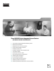
Quick Start Guide Cisco IAD2430 Series Integrated Access Devices INCLUDING LICENSE AND WARRANTY 1 Cisco 90-Day Limited Hardware Warranty Terms 2 Related Documentation 3 Equipment, Tools, and Accessories 4 Product Serial Number Location 5 Installing the Chassis 6 Installing a WAN or Voice Interface Card 7 Connecting Cables 8 Powering On the Cisco IAD 9 Performing the Initial Configuration 10 Obtaining Documentation 11 Documentation Feedback 12 Cisco Product Security Overview 13 Obtaining T
1 Cisco 90-Day Limited Hardware Warranty Terms There are special terms applicable to your hardware warranty and various services that you can use during the warranty period. Your formal Warranty Statement, including the warranties and license agreements applicable to Cisco software, is available on Cisco.com. Follow these steps to access and download the Cisco Information Packet and your warranty and license agreements from Cisco.com. 1. Launch your browser, and go to this URL: http://www.cisco.
2 Related Documentation User Documentation The latest information is always online. To view or print an online document in its original format, click the PDF icon. You can also order printed copies of many documents. See the “Obtaining Documentation” section on page 23. To find online user documentation (PDF and HTML formats): From Cisco.com at http://www.cisco.
Software Configuration Guide The software configuration guide provides additional detailed configuration information specific to Cisco IAD2430 series IADs. You can find this document at the following URL: http://www.cisco.com/univercd/cc/td/doc/product/access/iad/iad2430/sw_conf/index.htm or on Cisco.
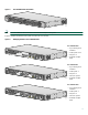
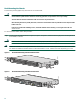
Figure 1 Cisco IAD2430 Series Front Panel CISCO IAD 88839 2400 Note The Cisco IAD2432-24FXS is used to illustrate the examples in this guide. Figure 2 identifies the different back panels and features of the models.
Cisco IAD2431-1T1E1 • T1/E1 ports: 2 • FE ports: 2 • WIC/VIC option • External compact flash IAD2431-1 88827 T1E1 Cisco IAD2432-24FXS • RJ-21 analog voice port • T1/E1 ports: 2 • FE ports: 2 88824 • WIC/VIC option The Cisco IAD2432-24FXS is used to illustrate back-panel function options. See Figure 3 on page 6. Note Not all models have all functions.
Items Included with Cisco IAD2430 Series IADs The following are included with each model in the series: • Rack-mount brackets for 19-inch rack; grounding lug and fasteners; power cord • Chassis guard for wall-mounting applications • Connected RJ-45-to-DB9 cable (labeled Console) • Connected RJ-45-to-DB-25 cable (labeled Auxiliary) • Cisco IAD2400 Series Regulatory Compliance and Safety Information • Quick Start Guide—Cisco IAD2400 Series Integrated Access Devices (this document) Note Power cords vary, dep
IMPORTANT SAFETY INSTRUCTIONS Warning This warning symbol means danger. You are in a situation that could cause bodily injury. Before you work on any equipment, be aware of the hazards involved with electrical circuitry and be familiar with standard practices for preventing accidents. To see translations of the warnings that appear in this publication, refer to the translated safety warnings that accompanied this device.
Chassis Installation Options You can set the chassis on a desktop, install it in a rack, or mount it on a wall. Tip Before proceeding, consider the location of the equipment with respect to a good ground. See the “Grounding the Chassis” section on page 13.
Rack-Mounting the Chassis The following warning applies only when the unit is rack-mounted: Warning To prevent bodily injury when mounting or servicing this unit in a rack, you must take special precautions to ensure that the system remains stable. The following guidelines are provided to ensure your safety: This unit should be mounted at the bottom of the rack if it is the only unit in the rack.
Telco 19-Inch Rack-Mounting with Rear Panel Forward 88842 Figure 7 Step 2 Install the chassis in the rack. Wall-Mounting the Chassis The following warning applies only when the unit is wall-mounted: Warning This unit is intended to be mounted on a wall. Please read the wall mounting instructions carefully before beginning installation. Failure to use the correct hardware or to follow the correct procedures could result in a hazardous situation to people and damage to the system.
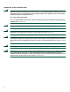
• Attach both brackets to the wall. Note For attaching to a wall stud, each bracket requires two #10 wood screws (round- or pan-head) with #10 washers, or two #10 washer-head screws. The screws must be long enough to penetrate at least 3/4 inch (20 mm) into supporting wood or metal wall stud. Note For hollow-wall mounting, each bracket requires two wall anchors with washers. Wall anchors and washers must be size #10. • Figure 9 shows the orientation required for installation.
1 Wall 3 Wall stud 2 Bracket 4 Keyhole (for starter screw) Grounding the Chassis Warning This equipment must be grounded. Never defeat the ground conductor or operate the equipment in the absence of a suitably installed ground conductor. Contact the appropriate electrical inspection authority or an electrician if you are uncertain that suitable grounding is available. Statement 1024 Warning Use copper conductors only.
Step 4 Attach the ground lug or ring terminal to the chassis as shown in Figure 10 or Figure 11. For the ground lug, use the two screws with captive locking washers provided. For a ring terminal, use one of the screws provided. Use a number 2 Phillips screwdriver, and tighten the screws to a torque of 8 to 10 in-lb (0.9 to 1.1 N-m). Step 5 Connect the other end of the ground wire to a grounding point at your site.
Note Contact your Cisco account representative for the most recent supported cards. For detailed information on installing and connecting interface cards, refer to the following: “Installing WAN and Voice Interface Cards in Cisco Modular Routers,” in the Cisco Interface Cards Installation Guide, at the following URL: http://www.cisco.com/univercd/cc/td/doc/product/access/acs_mod/cis2600/hw_inst/wic_inst/wic_doc/index.
Warning Before performing any of the following procedures, ensure that power is removed from the DC circuit. Statement 1003 Warning To prevent accidental discharge in the event of a power line cross, route on-premise wiring away from power cables and off-premise wiring, or use a grounded shield to separate the on-premise wiring from the power cables and off-premise wiring. A power line cross is an event, such as a lightning strike, that causes a power surge.
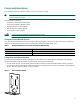
Figure 12 LAN, Administrative Access, and Power Connections 3 1 2 88845 Cisco IAD2430 series 4 6 5 Ethernet hub Modem PC 1 Fast Ethernet port 4 Fast Ethernet (straight-through) 2 Console port 5 RJ-45-to-DB9 console cable 3 AUX port 6 RJ-45-to-DB25 auxiliary cable Connecting WAN and Voice Cables Warning For connections outside the building where the equipment is installed, the following ports must be connected through an approved network termination unit with integral circuit protectio
Table 3 WAN and Voice Cable Selection (continued) Port or Interface Color or Type Connected To Cable (not included) VIC2-4FXO FXO RJ-11 Station side of analog PBX RJ-11 cable Analog voice FXS RJ-21 Distribution panel Figure 13 RJ-21-to-RJ-21 straight-through cable WAN and Voice Connections To CO Distribution panel 1 2 88872 Cisco IAD2430 series 3 Digital voice 4 PBX Network demarcation 1 RJ-21 cable 3 RJ-48 straight-through cable 2 RJ-45 cable (through a patch panel) to central of
To power on the Cisco IAD, follow this procedure: Step 1 Power on your terminal or PC, and configure it for 9600 bps, 8 data bits, 1 stop bit, and no parity. Step 2 Move the Cisco IAD power switch to the ON position. The green LED next to the auxiliary port should come on and the fan should operate. If this does not happen, see the power-on procedure in the Cisco IAD2430 Series Integrated Access Device Hardware Installation Guide.
Setting the Fast Ethernet Port IP Address To set an IP address for the Fast Ethernet port, follow the procedure below. After setting this address, you can configure the Cisco IAD remotely through a Telnet connection. Command Description Step 1 Router# configure terminal Enters global configuration mode. Step 2 Router(config)# enable password password Sets a password for the privileged EXEC mode. Step 3 Router(config)# interface Fast Ethernet 0/0 Enters interface configuration mode.
Command Description Step 9 Router(config)# exit Exits configuration mode. Step 10 Router# show controller t1/e1 1/0 Verifies the controller configuration.
Verifying and Saving Your Configuration To verify the configuration and save it in NVRAM so that the configuration remains in effect if the Cisco IAD is restarted, enter the following commands: Command Description Router# show running-config Displays the current operating configuration, including any changes you have made. Router# show startup-config Displays the configuration currently stored in NVRAM.
10 Obtaining Documentation Cisco documentation and additional literature are available on Cisco.com. Cisco also provides several ways to obtain technical assistance and other technical resources. These sections explain how to obtain technical information from Cisco Systems. Cisco.com You can access the most current Cisco documentation at this URL: http://www.cisco.com/univercd/home/home.htm You can access the Cisco website at this URL: http://www.cisco.
12 Cisco Product Security Overview Cisco provides a free online Security Vulnerability Policy portal at this URL: http://www.cisco.com/en/US/products/products_security_vulnerability_policy.html From this site, you can perform these tasks: • Report security vulnerabilities in Cisco products. • Obtain assistance with security incidents that involve Cisco products. • Register to receive security information from Cisco.
Note Use the Cisco Product Identification (CPI) tool to locate your product serial number before submitting a web or phone request for service. You can access the CPI tool from the Cisco Technical Support Website by clicking the Tools & Resources link under Documentation & Tools. Choose Cisco Product Identification Tool from the Alphabetical Index drop-down list, or click the Cisco Product Identification Tool link under Alerts & RMAs.
• Packet magazine is the Cisco Systems technical user magazine for maximizing Internet and networking investments. Each quarter, Packet delivers coverage of the latest industry trends, technology breakthroughs, and Cisco products and solutions, as well as network deployment and troubleshooting tips, configuration examples, customer case studies, certification and training information, and links to scores of in-depth online resources. You can access Packet magazine at this URL: http://www.cisco.
Corporate Headquarters Cisco Systems, Inc. 170 West Tasman Drive San Jose, CA 95134-1706 USA www.cisco.com Tel: 408 526-4000 800 553-NETS (6387) Fax: 408 526-4100 European Headquarters Cisco Systems International BV Haarlerbergpark Haarlerbergweg 13-19 1101 CH Amsterdam The Netherlands www-europe.cisco.com Tel: 31 0 20 357 1000 Fax: 31 0 20 357 1100 Americas Headquarters Cisco Systems, Inc. 170 West Tasman Drive San Jose, CA 95134-1706 USA www.cisco.