Cisco LightStream 1010 Titlepage Supports Management Module SM-CIS1002 Device Management
Copyright Notice Document 9032352-03. Copyright © January 2002 by Aprisma Management Technologies, Inc. All rights reserved worldwide. Use, duplication, or disclosure by the United States government is subject to the restrictions set forth in DFARS 252.227-7013(c)(1)(ii) and FAR 52.227-19. Liability Disclaimer Aprisma Management Technologies, Inc. (“Aprisma”) reserves the right to make changes in specifications and other information contained in this document without prior notice.
Contents INTRODUCTION 6 Purpose and Scope ........................................................6 Required Reading ...........................................................6 Supported Devices..........................................................7 The SPECTRUM Model ..................................................7 TASKS DEVICE VIEW DEVICE TOPOLOGY VIEW 20 APPLICATION VIEWS 21 Main Application View................................................... 21 Supported Applications .................
Contents Contents Switch Application Addresses View...........................33 Switch Application Traffic Parameter Table View......34 Switch Application AAL5 VCC Table View ................35 Switch Application Registered Services View ...........35 Accounting Control ....................................................36 Switch Application Accounting Selection Control Table View ................................................................
Contents Contents Interface Resource Management State Information View 72 Interface Resource Management Statistics Information View....................................................................73 Interface Resource Management Output Queue Configuration View........................................................74 Interface Resource Management Thresholds View...75 Switch Application Interface Configuration View...........75 ATM IF Configuration Table ......................................
Introduction This section introduces the SPECTRUM Device Management documentation for the Lightstream 1010 ATM Switch manufactured by Cisco. This introduction contains the following topics: • Purpose and Scope SPECTRUM and explanations of SPECTRUM functionality and navigation techniques, refer to the topics listed under Required Reading.
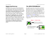
Introduction Supported Devices Supported Devices The SPECTRUM Model SPECTRUM management module SM-CIS1002 currently lets you model the Cisco LightStream 1010 ATM Switch. The LightStream 1010 is a five slot modular chassis that provides switched ATM connections to individual workstations, servers, LAN segments, or other ATM switches and routers, using fiber-optics, unshielded twistedpair (UTP), and coaxial cable.
Introduction The SPECTRUM Model The device-specific Icon Subviews menu options available from the Device icon are listed below. Option Fault Management The rest of this document covering the Cisco management module is organized as follows. • Tasks (Page 9) Accesses the... • Device View (Page 10) Fault Management View, which is described in the How to Manage Your Network with SPECTRUM documentation.
Tasks This section contains an alphabetical list of device management tasks, with each task providing one or more links to views that let you perform the task.
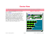
Device View This section describes the Device view and subviews available for models of Cisco devices in SPECTRUM. Figure 2: Access: From the Icon Subviews menu for the Device icon, select Device. This view (Figure 2) uses icons and labels to represent the device and its components, such as modules, ports, and applications.
Device View Interface Icon Subviews Menu Interface Icon Subviews Menu Interface Status View Table 1 lists the device-specific interface Icon Subviews menu options and the views to which they provide access. Access: From the Icon Subviews menu for the Interface icon in the Device view, select IF Status. Table 1: Interface Icon Subviews Menu Option Accesses the... Detail Interface Detail view, which displays packet, error, and discard breakdown statistics for the interface.
Device View Note: Note: Logical Device View Figure 3: Interface Icon The Lightstream 1010 ASP and PAMs may be installed in the Catalyst 5500 switch chassis. In the Catalyst 5500 switch chassis the ASP must be installed in slot number 13 and the PAMs installed in slots 9 through 12. (a) (b) ON 13 Logical Device View atm (d) The Logical Device view is a representation of the device configuration.
Device View Interface Icon c Interface Type Label/LightStream Interface Configuration View d Mac Address Label/LightStream Interface Address Translation Table View e Network Address Label Operational Status A read-only indicator displaying the current operational state of the interface. The possible states are ON, OFF, Testing, and Default which is not defined. Interface Label This label displays the interface (port) number.
Device View Interface Icon Table 3: Interface Types (Continued) Type Table 3: Description iso88024 ISO token bus iso88025 ISO token ring iso88026 ISO man starLan StarLAN IEEE 802.
Device View Interface Icon Interface Address Translation Table View In addition to the following information, you can double-click any entry in the table to access to the Interface Address Translation Information View, which contains the same information as the table view with the exception that it pertains only to the selected entry. Interface Index The value identifying the port. Physical Address The physical (MAC) address of the port. Network Address The network (IP) address of the port.
Device View Interface Icon Subviews Menu Interface Icon Subviews Menu Table 4: Links Table 4 describes the Interface icon devicespecific Subviews menu selections. Note: Note: Some of the interface Icon Subviews menu selections may be grayed out for all of the interface types except atm because they are not applicable to those interface types. Table 4: Contains two sub menu selections; Virtual Channels, described in this chapter, and Virtual paths, also described in this chapter.
Device View Interface Icon Subviews Menu If Index The index number identifying the port to which it is attached. Status The current status of the interface. The value of this object is only valid when the interface’s Administrative Status is set to “up”. Possible values are los, lof, loc, ais, yellowLine, yellowPath, lop, idle, yellowAlarm, plcpLOF, plcpYellow, maFERF, pathAis, and ocd. Plcp Bip Violations The number of Physical Layer Convergence Protocol (PLCP) BIP violations on the physical interface.
Device View Interface Icon Subviews Menu VPI Value The SVC’s Virtual Path Identifier (VPI) value, on this interface. Table 5: Value VCI Value The SVC’s Virtual Channel Identifier (VCI) value, on this interface. SVC Direction This value indicates whether the selected Virtual Channel Link (VCL) is the calling side, the side that has been called, the root side or the leaf for this address. Possible values are listed in Table 5.
Device View Interface Icon Subviews Menu Cast Type The VCL cast type, its possible values are: point to point, point to multi-point root, and point to multi-point leaf. Load Threshold The ON and OFF values are set to determine the point at which a load alarm will be turned on or off. Span Type The VCL span types which can be either a transit connection or a terminating one. If it is a transit connection, then it is passed on, if it is a terminating connection, then it ends there.
Device Topology View This section describes the Device Topology view available for models of the Cisco LightStream devices. Figure 4: Access: From the Icon Subviews menu for the Device icon, select Device Topology. The Device Topology view (Figure 4) shows the connections between a modeled device and other network entities. The lower panel of the view uses Interface icons to represent the device’s serial, network, and I/O ports.
Application Views This section describes the main Application view and the associated application-specific subviews available for models of Cisco devices in SPECTRUM. Figure 5: Main Application View Access: From the Icon Subviews menu for the Device icon, select Application. SpectroGRAPH: Application: Model Name Help File View Tools Bookmarks Main Application View When a device model is created, SPECTRUM automatically creates models for each of the major and minor applications supported by the device.
Application Views Supported Applications Supported Applications SPECTRUM’s applications can be grouped within two general categories as follows: • Applications associated with non proprietary MIBs. See Common Applications below. • Applications associated with device-specific MIBs. See Device-Specific MIBs (Page 23). Common Applications For the most part, these applications represent the non proprietary MIBs supported by devices.
Application Views - Supported Applications Device-Specific MIBs WAN Frame Relay Token Ring Ethernet Fast Ethernet rfc1317App rfc1285App rfc1315App 802.
Application Views The following device-specific applications are described in the remainder of this section: • Switching Application (LS_Switch_App) Switching Application (LS_Switch_App) Switching Application (LS_Switch_App) • Cisco Chassis Application (CiscoChas_App) (Page 48) This application provides access to ATM switching functionality for this device. The following application-specific Icon Subviews menu selections are available for the ATM switching application.
Application Views Switching Application (LS_Switch_App) consecutive ATM cells have header errors, an OCD event will occur. Table 6: Value TC Alarm Status This variable indicates that there is an alarm present for the TC Sublayer. The value lcdfailure indicates that a Loss of Cell Delineation (LCD) failure has been declared.
Application Views Switching Application (LS_Switch_App) you to create a new connection or remove an existing one. Low VPI The value of this object is equal to the VPI value at the ATM interface associated with this VC cross-connect. Row Status Procedure 1 Click the Index button to select an index value. This will display AVC Cross Connect Index dialog box which will provide an index.
Application Views Switching Application (LS_Switch_App) Row Status The status of an entry in the table. Possibilities are active, notInService, notReady, createAndGo, createAndWait, and destroy. H2L Last Change This value is the same as the MIB II’s System Up Time at the time the VC cross-connect became active in a high to low direction.
Application Views Switching Application (LS_Switch_App) Possible states are up or down indicating that the traffic flow is enabled or disabled respectively. Row Status The status of an entry in the table. Possibilities are active, notInService, notReady, createAndGo, createAndWait, and destroy.
Application Views Switching Application (LS_Switch_App) IF The index number associated with this interface. VPI The Virtual Channel’s VPI value on this interface. VCI The Virtual Channel’s VCI value on this interface. Admin Status The value of this object identifies the desired administrative status of the VCL. Possible states are up or down indicating that the traffic flow is enabled or disabled respectively. Oper Status The current operational status of the VCL.
Application Views Switching Application (LS_Switch_App) Slow Retry Interval Soft Permanent Virtual Connection (SPVC) retry rate, in seconds. Row Status The status of an entry in the table. Possibilities are active, notInService, notReady, createAndGo, createAndWait, and destroy. OAM End Loopback Enable end-to-end loopback on this virtual table. Switch Application VCL View To access this view, double click any entry within Switch Application VCL Table view.
Application Views Switching Application (LS_Switch_App) Out Cells The total number of cell transmitted on this VPL. is zero for a leaf VCL. This also means that this is the last leaf. AAL Encap Protocols Protocol for terminating the Virtual Channel, if the encapFlag value is set to aal5mux. Possible protocol values are: ip, xns, appletalk, clns, decnet, novell, apollo, vines, and other.
Application Views Switching Application (LS_Switch_App) Span Type The VCL span type; either a transit one or a terminating one. Config Type The configuration type of the VCL. Possible values are permanent, switch, soft, or other. Conn State The Connection State of this VCL, possible values are setup, release, not installed, down, and up.
Application Views Switching Application (LS_Switch_App) Cross Connect Id A unique value used to identify this VPL’s crossconnection. Switch Application Addresses View Row Status The status of an entry in the table. Possibilities are active, notInService, notReady, createAndGo, createAndWait, and destroy. In addition to the following information, this table also provides double-click access to the Switch Application Address View. Index The index value attached to this switch.
Application Views Switching Application (LS_Switch_App) Switch Application Traffic Parameter Table View Param 4 The fourth parameter of the ATM traffic descriptor. Access: From the Icon Subviews menu for the LS_Switch_App icon, select Traffic Parameter. Param 5 The fifth parameter of the ATM traffic descriptor.
Application Views Switching Application (LS_Switch_App) notInService, notReady, createAndGo, createAndWait, and destroy. Explicit Cat This object indicates the service category specified by the Traffic Descriptor. When defined this category determines the Service Category for the connection. Possible values are described in Table 7. Derived Cat This object defines the Service Category derived from the Traffic Descriptor.
Application Views Switching Application (LS_Switch_App) Parameter 1 An octet string used according to the value of the Registered Services Service ID. Row Status The status of this row. Possible values are: active, notInService, notReady, createAndGo, createAndWait, and destroy. Accounting Control These views are for the management, collection, and storage of accounting information as pertains to connections in a connection oriented network.
Application Views Switching Application (LS_Switch_App) Suffix. The value of this field cannot be modified if the value of Row Status is active. Table 8: Value Description The description of the accounting data, which will be stored when header information is stored in the file. Format The format of the data stored in the file. The value ber indicates the standard format. Command Commands that will cause the data stored in the file to either be written or read.
Application Views Switching Application (LS_Switch_App) Max Size The maximum size of the file, including header information. . Table 9: Value Switch Application Accounting Interface Table View Admin Status The desired state of accounting records across all interfaces. Oper Status The operational state of the collection of accounting records across all interfaces.
Application Views Switching Application (LS_Switch_App) PNNI Switch Application Accounting Trap Control View Nearly_full Trap Threshold A percentage of the maximum file size at which a ‘nearly_full’ trap is generated.
Application Views Switching Application (LS_Switch_App) would require a new computation of the background routes. Route Optimization Threshold Specifies the percentage reduction, in the administrative weight of the existing path, required to trigger route optimization. Insignificant Threshold Specifies the number of insignificant changes necessary to trigger a new computation of the background routes.
Application Views Switching Application (LS_Switch_App) contains the same information as the table view except that it pertains only to the selected entry. Table 10: Value Switch Application PNNI Interface Table View Interface A table of Cisco specific attributes used to configure a physical interface or subinterface on a switching system which is capable of being used for PNNI routing. Link Selection For Constant Bit Rate (CBR) or Variable Bit Rate (VBR) setups.
Application Views Switching Application (LS_Switch_App) Route Optimization Enables or disables the route optimization feature on an ATM interface. Table 11 describes Route Optimization values.
Application Views Switching Application (LS_Switch_App) Switch Application PNNI Precedence Table View Switch Application Route Address Table View This table specifies the precedence of different types of reachable addresses, double-clicking any entry within the table will open the Switch Application PNNI Precedence View which contains the same information as the table view except it pertains only to the selected entry. The precedence values are: Instance (Node Index. Route Address. Prefix Length.
Application Views Chassis Application (LS1010Chas_App) Chassis Application (LS1010Chas_App) Slots The number of slots in the chassis for plug-in modules. This application provides access to LightStream ATM chassis functionality for this device. The following subviews are available: Last Change The last time a physical (module) change was made to the chassis.
Application Views Chassis Application (LS1010Chas_App) PCMCIA Slot 0 Type Type of PCMCIA slot for 0. Possible values are: unknown, empty, and flash. Status Status of power supply 1. Possible values are: ok, fault, and unknown. Power Supply 0 LED LED status of power supply 1. Possible values are: red, yellow, green, and off. Type The type of power supply. Possible values are: powerone, astec, and empty. Admin Status Enable or disable power supply 0. Status Status of power supply 0.
Application Views Chassis Application (LS1010Chas_App) Chassis Application Module Group View Admin Status The administrative status of the module. Possible values are: enable, disable, and reset. Access: From the Icon Subviews menu for the LS1010Chas_App icon, select Module Group. In addition to the following information, this table also provides double-click access to the Chassis Application Module Group Configuration View. Module A unique value that identifies each module.
Application Views Chassis Application (LS1010Chas_App) Sub Module A unique value that identifies the sub-module to which this port is attached. Serial # The serial number of the sub-module. Hw Version The hardware version of the sub-module. Port A unique value identifying each port attached to a sub-module. Sw Version The software version of the sub-module. Description A descriptive string used by the agent to describe the sub-module. Ports The maximum number of ports supported by this sub-module.
Application Views Cisco Chassis Application (CiscoChas_App) CPU Admin Status CPU Administrative status of the switch. Possible values are ok and reset. Cisco Chassis Application (CiscoChas_App) Terminate OAM Flow Terminate all the incoming OAM cells to the CPU port. This application provides access to Cisco ATM Interface functionality for this device.
Application Views Cisco Chassis Application (CiscoChas_App) mci2e1t, mci2e2t, mci2e1s, mci2e1s1t, mci2e2s, csc-r, csc-r16, csc-r16m, csc-1r, csc-2r, csc-cctl1, csc-cctl2, csc-mec2, cscmec4, csc-mec6, csc-fci, csc-fcit, csc-hsci, csc-ctr, sp, eip, fip, hip, sip, trip, fsip, aip, mip, ssp, npm-4000-fddi-sas, npm-4000-fddidas, npm-4000-1e, npm-4000-1r, npm-4000-2s, npm-4000-2e1, npm-4000-2e, npm-4000-2r1, npm-4000-2r, npm-4000-4t. Description A description of this card.
Application Views Cisco Interface Application (CiscoIFApp) ROM Information This section of the Chassis Card View provides the following information about the ROM installed in the chassis: Non-volatile RAM Size (bytes) The total size, in bytes, of non-volatile configuration memory. Cisco Interface Application (CiscoIFApp) ROM Monitor Version The version number of the ROM monitor. ROM Software Version The version number of the ROM system software.
Application Views Terminal Server Application (CiscoTSApp) Type The type of line. Possibilities are: unknown, console, terminal, line-printer, virtualterminal, and auxiliary. Length In Lines Length, in lines, of the terminal’s screen, attached to this line. Width in Char Width, in characters, of the terminal’s screen, attached to this line. Autobaud Whether the line will autobaud. Speed In The input speed at which the line is running. Escape Char Escape character used to break out of active sessions.
Application Views Cisco Memory Pool Application Noise Count of garbage characters received when the line is inactive. State A boolean value indicating whether the session is active. Line Number A unique value used to identify the line. Idle Time, in seconds, that the session has been idle. Time Active The time, in seconds, since the line was activated. Line A unique value used to identify the line. Terminal Server Session View Session A unique value used to identify the session.
Application Views Cisco Memory Pool Application Cisco Memory Pool Monitor Table View Free The number of bytes from the memory pool that are currently unused on the managed device. Access: From the Icon Subviews menu for the Cisco_Mem_ Application icon, select Memory Pool Monitor. Largest Free Indicates the largest number of contiguous bytes from the memory pool that are currently unused on the managed device. This table displays memory pool monitoring entries.
Performance Views This section provides brief descriptions of the Performance views available for the Cisco devices in SPECTRUM. Performance views display performance statistics in terms of a set of transmission attributes, e.g., cell rates, frame rates, % error, etc. A typical view is shown in Figure 6. The instantaneous condition of each transmission attribute is recorded in a graph. The statistical information for each attribute is presented in the adjacent table.
Performance Views Device Performance View Device Performance View Access: From the Icon Subviews menu for the Device icon, select Performance. Current and historical frame transmission information is provided via the following attributes. • • • • • • Frame Rate % Delivered % Forwarded % Transmit % Error % Discarded Port Performance View Access: From the Icon Subviews menu for the Device Interface icon, select Performance.
Configuration Views This section describes the various Configuration views available for models of the Cisco devices in SPECTRUM. Configuration views let you view and modify current settings for the modeled device and its interfaces, ports, and applications.
Configuration Views Device Configuration View Figure 7: Device Configuration View SpectroGRAPH: Model Name File View Tools Bookmarks Help Why Last Reload An ASCII text string explaining why the system was last restarted. Device Configuration View Sort Manufacturer Device Type Primary Application Find Index System Up Time Network Address Model Name Contact Description Location Update Type Host Name An ASCII text string displaying the name of the host.
Configuration Views Device Configuration View Operation Status The current operational state of the port (On, Off, or Testing). Running Configuration Changes This button opens the Cisco Running Config Event/Alarm Configuration View. Interface Configuration Table Admin Status The desired operational state of the port (On, Off, or Testing). This section of the Cisco Configuration view provides the following port configuration information for each of the Cisco’s ports.
Configuration Views Device Configuration View redundancy update, and reconfigure aspects of your network connections. Reconfigure due to LINK UP/Down events Set this button to “True” to cause SPECTRUM to verify the interfaces displayed when a LINK UP or LINK DOWN event is received. Preferred Addresses This button opens the Preferred Addresses dialog box which allows you to select the redundant preferred address for the device.
Configuration Views Device Configuration View Interface Address Translation Table View New Host Addr This field replaces the Previous Host Addr field when the Upload Net Config file is selected. Access: In the Configuration view, click the IF Address Translation button. This view cross-references device IP addresses to device MAC addresses for selected nodes between networks.
Configuration Views Upload Net Config File Initiates the transfer of configuration file from host to server. TFTP Server Addr Address used to send the configuration file from server to a host. File Name The file name where you are storing the configuration. Device Configuration View Previous File Name The name of the last host configuration file used by the device. New Host Addr This field replaces the Previous Host Addr field when the Upload Host Config file is selected.
Configuration Views Device Configuration View Cisco Running Config Event/Alarm Configuration View Generate Event For All Models Of This Model Type Access: In the Configuration View, click the Running Configuration Changes button. This view lets you set when the attribute ccmHistoryRunningLastChanged is checked. This attribute tells you if and when the configuration has changed. This view also lets you set the generation of either an event or an alarm if it does change.
Configuration Views Note: Note: Device Configuration View Protocol The protocol to be used for any copy. Will default to tftp if not specified. If the copy operation occurs locally on the SNMP agent, this object may be ignored by the implementation. A Cisco device that has firmware 12.1 will have the following additional menu buttons in the Configuration view. Memory Pool Monitor Opens the Cisco Memory Pool Monitor Table View (Page 53). Config Copy Table Opens the Cisco Config-Copy Table View.
Configuration Views Device Configuration View Address and File Name must also be created, and these three objects together (Dest File Type, Server Address, File Name) will uniquely identify the destination file. If the Dest File Type is iosFile, the File Name must also be created, and the two objects together (Dest File Type, File Name) will uniquely identify the destination file. Possible types are networkFile, iosFile, startupConfig, runningConfig, and terminal.
Configuration Views Interface Configuration View Time Completed The time the Copy State last transitioned from running to successful or failed states. This object is instantiated only after the row has been instantiated. Its value will remain 0 until the request has completed. Fail Reason The reason why the config-copy operation failed. This object is instantiated only when the Copy State for this entry is in the failed state. Access: Select IF Configuration from the Icon Subviews menu.
Configuration Views Interface Configuration View Side The side of the network user interface which is either a user or network side. Not Applicable indicates that it is other than uni or iisp. ILMI Keep Alive The amount of time, in seconds, that should elapse between successive ILMI keepalive messages sent on this interface. A value of 0 disables this function. IF Type Displays the type of interface. Auto-configuration must be disabled to modify this field. Table 12 lists all possible values.
Configuration Views Switch Resource Management Configuration View Active SVCs The number of active Switched Virtual Channels (SVCs) at this interface. Switch Resource Management Configuration View PVPs The number of Permanent Virtual Paths (PVPs) at this interface. Access: From the Icon Subviews menu for the Switching app icon, select Resource Management. PVCs The number of Permanent Virtual Channels (PVCs) at this interface.
Configuration Views Switch Resource Management Configuration View Cell Count The number of all cells on all output queues of the switch at any time of a particular priority. In addition to the tables, this view also provides the following information. Peak to Peak CDV The default peak-to-peak Cell Delay Variation (CDV) for the service category. It applies only to cbr and vbr-rt service categories. Specifying a value of 16777215 signifies that this parameter should not be checked during connection setup.
Configuration Views Switch Resource Management Configuration Details View Switch Resource Management Configuration Details View Rate Requested This field reflects an explicit configuration of the state of pacing, expressed in kilobits per second, for this interface. If the value of this field is zero, pacing is disabled. Access: From the Icon Subviews menu for the Device icon, select Resource Management. This view contains more the following detailed network configuration information for the device.
Configuration Views Switch Resource Management Configuration Details View chapter, Clicking on Thresholds opens the Interface Resource Management Thresholds View described in this chapter. that MaxUbr <= MaxAgg.If the object is set to -1, the object is considered to be unspecified. This object is not defined for logical port ATM interfaces.
Configuration Views Switch Resource Management Configuration Details View MaxAgg. (not defined for logical port ATM interfaces). considered to be unspecified. This object is not defined for logical port ATM interfaces. Link Share Min VBR A Configuration in the Controller Link Sharing (CLS) scheme which specifies a minimum amount of VBR traffic that can be reserved in a traffic direction on an interface.
Configuration Views Switch Resource Management Configuration Details View for VBR connections in a traffic direction on an interface. It is specified in cells-per-second. Max VBR Tolerance This value specifies the maximum limit parameter used in the Generic Cell Rate Algorithm (GCRA) for traffic policing that can be specified for VBR connections in a traffic direction on an interface. It is specified in cell-times.
Configuration Views Switch Resource Management Configuration Details View Alloc Cell Rate (TX) The allocated cell rate, in cells per second, for traffic transmitted on the interface for this Service Category. This is the bandwidth available to connections. Interface Resource Management Statistics Information View # Signalled Conns The number of signalled connections (VC or VP) of this Service Category currently allocated on this interface. All of these fields are cross-referenced by Service Category.
Configuration Views Switch Resource Management Configuration Details View Failed (Delay) The number of resource allocation requests which are considered to be in error because they exceed cell loss criterion. Failed (Cell Delay Var) The number of resource allocation requests which are considered to be in error because they exceed cell delay variation criterion.
Configuration Views Switch Application Interface Configuration View Max Size Force Changes the value of the Requested Maximum Size of a queue. Switch Application Interface Configuration View Cell Count Count of the number of cells in the output queue. Access: From the Icon Subviews menu for the Switching App icon, select Interface Configuration. This view contains more detailed network configuration information for the device. This view is broken into two tables that are detailed below.
Configuration Views Switch Application Interface Configuration View Config VCCs The number of configured VCCs on the interface. Max VPI Bits Maximum number of Virtual Path Identifier bits (VPI bits) allowed on this interface Neighbor IF Name The interface name of the neighbor system connected to the far end of this interface.
Configuration Views Switch Application Interface Configuration View Active SVCs The number of SVCs currently active on the interface. Xmit Cells The number of cells transmitted on this interface. Recv Cells The number of cells received on this interface.
Model Information View Model Information View This section provides a brief overview of the Model Information view. This view displays administrative information about the device and its applications and lets you set thresholds and alarm severity for the device. Figure 8 shows a sample Model Information view. The layout of this view is the same for all model types in SPECTRUM but some information will vary depending on the model it defines.
Model Information View Device Management Page 79 Cisco LightStream 1010
Model Information View Device Management Page 80 Cisco LightStream 1010
Device Management Page 81 Cisco LightStream 1010
Index A Accounting Control 36 Active SVCs 67 Active SVPs 66 Address Translation 11 Adminisrtative Status 13 Administrative Status Label 12, 13 Alarm Discard Threshold 19 Application View 24 Applications 21 Applications Supported Common Applications 9 ATM IF Configuration Table Address Type 76 Admin Address 76 Conf VPCs 75 Config VCCs 76 IF Index 75 ILMI VCI 76 ILMI VPI 76 Max VCCs 75 Max VCI Bits 76 Max VPCs 75 Max VPI Bits 76 Neighbor Address 76 Neighbor IF Name 76 Device Management ATM Switch Application
Index Chassis Appliction Port Group Interface 47 Module 47 Port 47 Sub Module 47 Sub Module Group Admin Status 47 Description 47 Hw Version 47 Module 46 Ports 47 Serial # 47 Sub Module 46 Sw Version 47 Type 46 Chassis Card View 48 Description 49 Hardware Ver. 49 Serial Number 49 Slot 48 Software Ver.
Index IFChas_App 50 In Cells 19 Interface Index 15 Status 11 Status of 13 Type 13 Interface Address Translation Table View 60 Interface Configuration Table 58 Interface Icon Interface label 13 Interface Icon, Device View Administrative Status Label 13 Network Information Label 15 Interface Label 13 Interface Resource Management State Information # Permanent Conns 73 # Signalled Conns 73 Alloc Cell Rate (TX) 73 Avail Cell Rate (TX) 72 Max Cell Trans.
Index LightStream Switch Application Traffic Parameter Table View 34 LightStream Switch Application Virtual Channel Link Table View 28 Link Table View 28 Row Status Procedure 28 Links 18 Load Alarm Threshold 19 Low VPI 26 LS_Switch_App 24 LS010Chas_App 44 M MAC Address Label 14 Mac Address Label 13 Management Tasks 9 Mask 11 Model Information 78 Types of 7 Module 47 Index Network/Host Configuration View 60 O Operational Status 13 Out Cells 19 S P P Bit Parity Errors 17 Packet Threshold 19 Path Parity
Index VPI 35 Accounting File Control Table View Command 37 Cur Size 37 Description 37 Format 37 Index 36 Interval 37 Max Size 38 Min Age 37 Name 36 Row Status 37 Accounting Interface Table View Accounting Data Enabled 38 Admin Status 38 Agent Mode 38 Index 38 Oper Status 38 Protection 38 Accounting Selection Control Table View File 36 Index 36 List 36 Row Status 36 Subtree 36 Type 36 Accounting Trap Control View Nearly_full Trap Threshold 39 Traps Enabled Status 39 Application Addresses View Device Managem
Index End Minute 42 Interface 41 Interval 42 Link Selection 41 Route Optimization 42 Start Hour 42 Start Minute 42 PNNI Node Table View Internal Summary Address(es) 40 Maximum PTSE Requests 40 Name 40 Redistribute Static Routes 40 Scope Mapping 40 Registered Services View ATM Address 35 Instance (IF Index, Service ID, Address Index) 35 Parameter 1 36 Row Status 36 TC Sublayer Table View IF Index 24 OCD Events 24 TC Alarm Status 25 Traffic Parameter Table View Derived Cat 35 Descriptor Type 34 Explicit Cat
Index Low Index 27 Low VPI 27 Row Status 28 Switch Application Virtual Path Link Table View 32 Switch Application VPL Table View Admin Status 32 Cross Connect Id 33 IF 32 Oper Status 32 Rcv Descr Index 32 Row Status 33 Xmit Descr Index 32 Switch Interface Physical Layer view 25 Switch Resource Management Configuration View Default QOS Objective 67 Peak to Peak CDV 68 QOS CLR 68 QOS Max 67 Queued Cells 68 ABR Congestion Notify 68 Cell Count 68 Cell Limit 68 Over Subscription Factor 68 Priority 68 SCR Margin
Index Index VPI 18, 29 VPI Value 18 X Xmit Led 66 Device Management Page 89 Cisco LightStream 1010