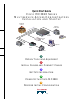
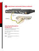
Quick Start Guide C I S C O MC3810 S E R I E S MULTISERVICE ACCESS CONCENTRATORS INSTALLATION AND STARTUP Telephone network Digital or analog PBX K E1 T1/ 64 r nX o Cisco MC3810 Ethernet hub SNA Computer Video codec Video 1 OBTAIN TOOLS AND EQUIPMENT 2 INSTALL CHASSIS AND CONNECT CABLES 3 GET SITE INFORMATION 4 POWER UP THE CISCO MC3810 5 PERFORM INITIAL CONFIGURATION
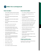
Obtain Tools and Equipment Items Included Items Not Included • Cisco MC3810 multiservice access concentrator • Four screws for installing the chassis in a rack • Rack-mount brackets, power cord, and spare set of rubber feet • E1 channel service unit/data service unit (CSU/DSU) • RJ-45-to-DB-9 female DTE adapter (labeled TERMINAL) • PC running terminal emulation software for administrative access • RJ-45-to-DB-25 female DTE adapter (labeled TERMINAL) • Modem for remote administrative access
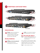
Install Chassis and Connect Cables Front panel forward T1/E1 1 2 E&M 3 E&M E&M 4 5 E&M 6 E&M FXO Rear panel forward T1/E1 1 2 E&M 2 E&M 3 E&M 4 5 E&M FXO E&M 6 FXO FXO Rear panel forward, center-mount telco Safety Information Warning See the Cisco MC3810 Series Caution Do not remove the rubber feet. Multiservice Access Concentrators Hardware Installation Guide for safety information you need to know before working on the Cisco MC3810.
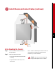
Install Chassis and Connect Cables (continued) Power supply and fan at the top 3 Vertical wall stud Wall-Mounting the Chassis Step 1 Install the smaller brackets as shown in the figure above. Step 2 Attach the chassis to the wall. • Position the end nearest the power cable at the top • Align screws with a wall stud, or use wall anchors Note: Screws for attaching the chassis to a wall are not included. You need to provide four screws suitable for your wall installation.
Install Chassis and Connect Cables (continued) Identifying Cable Types 8-Conductor Rollover Cable Pin 1 Same color Pin 8 Hold the connectors side-by-side, with the tab at the back. The colored wires are in the opposite sequence at opposite ends of the cable. If your cable came from Cisco Systems, pin 1 is white on one plug, and pin 8 is white on the opposite plug. (A rollover cable reverses the wire connections at the opposite ends: 1 to 8, 2 to 7, 3 to 6, 4 to 5, 5 to 4, 6 to 3, 7 to 2, and 8 to 1.
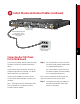
Install Chassis and Connect Cables (continued) T1/E1 1 E&M 2 E&M 3 E&M 4 55 E&M E&M FXO 6 FXO FXO T1/E1 trunk port (RJ-48 shown) Cisco MC3810 RJ-48 straight-through cable or two 75-ohm coaxial cables with BNC connectors (not shown) Network demarcation (RJ-48 shown) Connecting the T1/E1 Trunk Port to the Network If you are using a T1/E1 network interface, connect the T1/E1 trunk port to a network demarcation device.
Install Chassis and Connect Cables (continued) BRI 0 S/T 1 2 3 4 5 T1/E1 6 Cisco MC3810 BRI S/T backup port (CB-1D) 8-conductor straight-through cable NT1 ISDN wall jack (U interface) S/T U 6 Connecting the BRI S/T Backup Port to the Network If your Cisco MC3810 supports BRI S/T backup, connect the BRI S/T backup port to the ISDN network. Use an 8-conductor straight-through cable (not included). Step 1 Connect one end of the cable to the port labeled BRI 0 S/T on an orange background.
Install Chassis and Connect Cables (continued) T1/E1 1 E&M 2 E&M 3 E&M 4 5 E&M 6 E&M FXO FXO Serial 0 port Serial 1 port Cisco serial transition cables Cisco MC3810 CSU/DSU Connecting Synchronous Serial Ports You can connect the serial 0 port to a Frame Relay network or to user equipment. You can connect the serial 1 port to user equipment. Use one of the Cisco serial transition cables (not included).
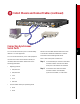
Install Chassis and Connect Cables (continued) T1/E1 1 E&M 2 E&M 3 E&M 4 5 E&M 6 E&M FXO Cisco MC3810 10BaseT port (RJ-45) 8 Straight-through Ethernet cable 7 1 Ethernet hub 8 Connecting the Ethernet Port for LAN Access If you are using a 10BaseT Ethernet LAN, connect the Ethernet 0 port to the Ethernet hub. Use a standard, straight-through, 10BaseT Ethernet cable (not included). Step 1 Connect the cable to the Ethernet 0 port (yellow).
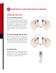
Install Chassis and Connect Cables (continued) FXS port FXO port E&M port T1/E1 1 2 3 4 5 6 Cisco MC3810 RJ-11 jack to central office PBX Telephone Connecting Analog Voice Ports Connect analog voice ports as follows: • FXS port—(gray) to telephone or fax equipment • FXO port—(pink) to central office (CO) line • E&M port—(brown) to analog PBX Use an RJ-11-to-RJ-11 standard telephone cable (not included) for each FXO or FXS port.
Install Chassis and Connect Cables (continued) T1 T1/E1 T1/E1 Cisco MC3810 Digital voice port (RJ-48 shown) RJ-48-to-RJ-48 rollover cable or two 75-ohm coaxial cables with BNC connectors (not shown) 10 PBX Connecting the T1/E1 Digital Voice Port If your Cisco MC3810 has a T1/E1 digital voice port, connect it to a digital PBX. Step 1 If the digital voice port has an RJ-48 jack, use an RJ-48-to-RJ-48 rollover cable (not included), or a special cable if required for your application.
Install Chassis and Connect Cables (continued) BRI voice ports (CB-1D) BVM T1/E1 ALM B2 B1 ALM B2 B1 BRI 1 BRI 2 ALM B2 B1 T1/E1 ALM B2 B1 BRI 3 BRI 4 Cisco MC3810 8-conductor cables 11 PBX (PINX) Connecting BRI S/T Voice Ports If your Cisco MC3810 has BRI S/T voice ports, connect them to a Private Integrated Services Network Exchange (PINX). Step 1 Connect one end of each cable to the appropriate BRI S/T voice port on the BRI voice module (BVM).
Install Chassis and Connect Cables (continued) T1/E1 Serial port 0 or 1 Cisco MC3810 VDM port Dialing port Video data port V.35 DCE with RI cable RS-366 cable 26427 Monitor and camera Video codec 12 Connecting Video Dialing Module If your Cisco MC3810 has a video dialing module (VDM), connect the VDM port and one of the Cisco MC3810 serial ports to the video codec. Step 1 For the dialing interface, use an RS-366 cable with one 26-pin connector and one DB-25 connector (included with VDM).
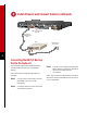
Install Chassis and Connect Cables (continued) T1/E1 1 E&M 2 E&M 3 E&M 4 5 E&M 6 E&M FXO Cisco MC3810 Console port (RJ-45) RJ-45-to-RJ-45 rollover cable PC (laptop) RJ-45-to-DB-9 or RJ-45-to-DB-25 adapter (labeled TERMINAL) Connecting the Console Port Note: If you are going to configure remotely, skip this procedure and go to the next page. Step 1 If you are using a local PC or ASCII terminal to configure your Cisco MC3810, connect it to the console port.
Install Chassis and Connect Cables (continued) AVT T1/E1 1 E&M 2 E&M 3 E&M 4 5 E&M E&M 6 FXO Cisco MC3810 Auxiliary (AUX) port (RJ-45) RJ-45-to-RJ-45 rollover cable Modem RJ-45-to-DB-25 adapter (labeled MODEM) 14 Connecting the Auxiliary Port Note: If you are going to configure locally, follow the procedure on the previous page. Step 1 Connect the adapter labeled MODEM to your modem.
Install Chassis and Connect Cables (continued) T1/E1 1 E&M 2 E&M 3 4 E&M 5 E&M E&M 6 FXO Cisco MC3810 Power switch To power outlet Connecting the Power Cable Note: This procedure is for AC power. If your Cisco MC3810 operates on DC power, see the Cisco MC3810 Series Multiservice Access Concentrators Hardware Installation Guide for instructions on connecting DC power cables.
Get Site Information Get This Information from Your Network Administrator This table provides space to write down information you need to run the System Configuration Dialog (also called the setup script).
Power Up the Cisco MC3810 Checklist for Power-Up You are ready to power up the Cisco MC3810 if it meets these requirements: • Securely mounted • Power connected; Cisco RPS powered on, if used as the power source • Interface cables connected Power-Up Procedure Perform this procedure to power up your Cisco MC3810 and verify that it goes through its initialization and self-test. When this is finished, the Cisco MC3810 will be ready to configure.
Perform Initial Configuration This section shows how to perform some basic configurations from a local or remote console, using the Cisco command-line interface. For complete configuration procedures, see the Cisco MC3810 Series Multiservice Access Concentrators Software Configuration Guide.
Perform Initial Configuration (continued) Step Command Purpose 9 router(config-if)# no shutdown Activate the Ethernet port. Messages similar to the following appear: %LINEPROTO-5-UPDOWN: Line protocol on Interface Ethernet0, changed state to up %LINK-3-UPDOWN: Interface Ethernet0, changed state to up router(config-if)# 10 router(config-if)# exit Return to global configuration mode. 11 router(config)# line vty 0 4 Enter line configuration mode.
Perform Initial Configuration (continued) Configuring Basic Settings for Serial Ports 0 and 1 To configure basic settings for serial ports 0 and 1, do the following: 20 Step Command Purpose 1 router> show interface serial Display the default configuration. 2 router> enable Enable the configuration. 3 router# configuration Enter configuration mode. 4 router(config)# network-clock base-rate {56k | 64k} Configure the network clock base rate setting.
Perform Initial Configuration (continued) Configuring T1/E1 Controller Settings for T1/E1 Ports There can be two T1/E1 ports in a Cisco MC3810: a trunk port and a digital voice port. The T1/E1 trunk port is physically located in the multiflex trunk module (MFT). It supports balanced T1 per ANSI T1.403, and it supports balanced and unbalanced E1 per ITU G.703. The MFT has a built-in CSU/DSU. The T1/E1 digital voice port is physically located in the digital voice module (DVM).
Perform Initial Configuration (continued) Configuring T1 Controller Settings To configure T1 controller settings, do the following in controller configuration mode: 22 Step Command Purpose 1 Configure the cable length setting by doing one of the following: router(config-ctrl)# cablelength short {133 | 266 | 399 | 533 | 655} Configure the cable length if the length is 655 feet or shorter. router(config-ctrl)# cablelength long {gain26 | gain36} {-15db | -22.5db | -7.
Perform Initial Configuration (continued) Basic Voice-Port Configuration This section has separate procedures for analog, digital, and ISDN BRI voice ports. Use the analog procedure to configure voice ports on the analog voice module (AVM). Use the digital procedure to configure voice ports on a T1 or E1 line on a digital voice module (DVM) or multiflex trunk module (MFT). Use the BRI procedure to configure voice ports on the BRI voice module (BVM).
Perform Initial Configuration (continued) Configuring Analog Voice Ports To configure the basic analog voice-port settings, perform the following tasks: Step Command Purpose 1 router> configure terminal Enter global configuration mode. 2 router(config)# voice-port slot/port Enter voice-port configuration mode, and specify the voice port you want to configure by entering the logical slot number and port number (see table on page 23).
Perform Initial Configuration (continued) Step Command Purpose 7 router(config-voiceport)# cptone country Configure the voice port for the local territory’s call progress tone setting. The call progress tone setting determines the settings for dialtone, busytone, and ringback tone. The default for this command is northamerica. For a list of supported countries, see the Cisco IOS Voice, Video, and Home Applications Command Reference.
Perform Initial Configuration (continued) Step Command Purpose 6 router(config)# voice-port slot/port Enter voice-port configuration mode, and specify the voice port you want to configure by entering the logical slot number and port number (see table on page 23). The following commands affect only the voice port you specify here. 7 router(config-voiceport)# dial-type {pulse | dtmf} Change the transmit dial type if necessary (FXO and E&M ports only). The default is dtmf.
Perform Initial Configuration (continued) Verifying Your Analog or Digital Voice-Port Configuration You can test your analog or digital voice-port configuration by doing the following: • Pick up the handset of an attached telephony device and check for dial tone. • If you have dial tone, check for DTMF detection. If the dial tone stops when you dial a digit, the voice port is probably configured properly.
Perform Initial Configuration (continued) Configuring ISDN BRI Voice Ports To configure the basic ISDN BRI voice-port settings, perform the following tasks: Step Command Purpose 1 router> configure terminal Enter global configuration mode. 2 router(config)# isdn switch-type basic-qsig Configure the global ISDN switch type as basic-qsig for the BRI voice ports. Note You can configure the ISDN switch type in either global or interface configuration mode.
Perform Initial Configuration (continued) Step Command Purpose 9 router(config-interface bri 1)# isdn overlap-receiving Activate overlap signaling to the destination PBX. 10 router(config-interface bri 1)# isdn network-failure-cause cause code Specify the cause code to pass to the PBX when a call cannot be placed or completed because of internal network failures. Possible values are from 1 to 127.
Corporate Headquarters Cisco Systems, Inc. 170 West Tasman Drive San Jose, CA 95134-1706 USA http://www.cisco.com Tel: 408 526-4000 800 553-NETS (6387) Fax: 408 526-4100 European Headquarters Cisco Systems Europe s.a.r.l. Parc Evolic, Batiment L1/L2 16 Avenue du Quebec Villebon, BP 706 91961 Courtaboeuf Cedex France http://www-europe.cisco.com Tel: 33 1 69 18 61 00 Fax: 33 1 69 28 83 26 Americas Headquarters Cisco Systems, Inc. 170 West Tasman Drive San Jose, CA 95134-1706 USA http://www.cisco.