Performance Route Processor Installation and Configuration Product Number: PRP-2=, PRP-3= Document Order Number: OL-17436-01 This hardware installation and configuration note describes the performance route processor (PRP) PRP-2 and PRP-3 route processors for use in Cisco XR 12000 Series Routers and Cisco 12000 Series Routers.
Important Information Important Information This section contains information about the following hardware and software requirements: • Router Information, page 2 • Cisco IOS XR Software Requirements, page 2 • Hardware Revision Requirements, page 3 Router Information For hardware installation and maintenance information about the Cisco XR 12000 Series Router, refer to the installation and configuration guide for your router.
Product Overview Hardware Revision Requirements To ensure compatibility with the software, the PRP should have a specific hardware revision level or greater. The hardware revision number is printed on a label affixed to the component side of the card. The hardware revision number can also be displayed using the show diags slot-number command. The minimum hardware revision number for PRP-3 (product number PRP-3=) is 73-10255-02.
Product Overview improved scalability, higher system memory, faster packet processing. Because PRP-3 does not support Cisco IOS Software, the bootflash memory no longer exists in PRP-3. PRP-3 ROMMON has software intelligence to download a Cisco IOS XR image without the support of bootflash memory. Note PRP-3 supports Cisco XR 124xx (10 G per slot fabric) and Cisco XR 128xx (40 G per slot fabric) Router chassis only. PRP-3 does not support Cisco XR 120xx Router chassis (2.5-G low-speed fabric).
Product Overview The PRP-3 contains the following components: Note • Power PC Processor—Power PC 8641D Dual Processor Central Processing Unit (CPU) e600 cores running at 1.3 GHz each. • Memory—Default internal and external compactflash of 2 GB each (2 x 2 GB = total 4 GB) and provides an option for upgrading the compact flash to 8 GB (2 x 4 GB). • Hard disk drive—80-GB hard disk drive installed on the PRP-3 board.
Product Overview Table 2 Differences Between PRP-2 and PRP-3 Hardware or Software Component PRP-2 Specifications PRP-3 Specifications Flash Disk 2 PCMCIA slots 1 External CompactFlash slot BITS 2 BITS inputs 2 BITS inputs Serial Interface Console + Aux Console + Aux Hard Drive 40-GB 2.5” HDD 80-GB 2.5” SATA HDD Operating System Cisco IOS Releases Supported Cisco IOS XR Software Release 3.8.
Product Overview PRP-3 ROMMON Changes The PRP-3 ROMMON in Cisco IOS XR Software Release 3.8.0 has significant changes and more software intelligence than the PRP-2 ROMMON of previous releases. The following sections discuss in detail the changes introduced in PRP-3 ROMMON. • Capability of ROM Monitor to Netboot • FAT32 File System Support • ROMMON Logical Divisions Capability of ROM Monitor to Netboot ROMMON is the initial program that loads in Cisco IOS XR software. It loads the mini.
Product Overview 1.330GHz dual-core MPC8641D Rev 2.1, 532MHz MPXclk Discovering memory in slot DIMM1 ......................... Discovering memory in slot DIMM2 ......................... Pausing between init of DDR1 and DDR2... Testing low memory ....................................... Loading main ROMMON image ................................ Verifying loaded image ................................... Load succeeded; launching target .........................
Product Overview Destination 10.12.0.0 10.14.0.0 223.255.254.0 Tip Netmask 255.255.0.0 255.255.0.0 255.255.255.0 Gateway * * 10.12.0.1 Metric 0 0 1 Interface eth0 eth1 eth0 To change the IP Address of the TFTP server or gateway, delete the route details from the route table by executing the following command. rommon 7 > route del 223.255.254.0 255.255.255.0 Route successfully deleted Step 6 Save the changes (route table configuration) to NVRAM.
Product Overview rommon 3> boot tftp://223.255.254.254/... Note During the PRP-3 booting, if you want to go back to the ROMMON prompt, press Ctrl-Break to force it back into ROMMON. This has to be done in the early stage of booting. PRP Hardware Components Figure 3 shows the locations of the various hardware components on the PRP-2. Memory options and functions for both are listed in Table 3.
Product Overview 5 Ethernet ports 12 SDRAM DIMM: Bank 1 - Socket number U15 6 BITS ports1 13 SDRAM DIMM: Bank 2 - Socket number U18 7 Auxiliary port 14 Hard disk drive (optional) 1. BITS functionality is currently not supported. Support for BITS on the Cisco 12000 Series Router will be provided through an upgrade to your switch fabric card (SFC) in the future.
Product Overview Figure 4 PRP-3 (Horizontal Orientation) 272360 5 4 1 2 3 12 1 SDRAM DIMM: Bank 1 - Socket number U8 2 SDRAM DIMM: Bank 2 - Socket number U10 3 External Compact Flash 4 Hard Disk (80 GB) 5 Internal Compact Flash OL-17436-01
Product Overview Table 4 PRP-3 Memory Components Type Description Location 2 2 GB (Default) for each DDR2 DRAM for a total system memory of 4 GB, option for upgrade to total system memory of 8 GB (4 GB each). Two 2-GB default DDR2 DRAM for main CiscoIOSXR software functions. Provision for optional upgrade to 4 GB also possible to provide total system memory of 8 GB.
Product Overview NVRAM NVRAM provides 2 MB of memory for system configuration files, software configuration register settings, and environmental monitoring logs. This information is backed up with built-in lithium batteries that retain the contents for a minimum of 5 years. NVRAM is not user configurable or field replaceable. Flash Memory Flash memory allows you to remotely load and store multiple Cisco IOS software and microcode images.
Product Overview PRP LEDs The following LEDs are used on the PRP: • Status LEDs • Display LEDs Status LEDs The PRP-2 has the following LED indicators: • Two Flash disk activity LEDs, one for each Flash disk slot (labeled SLOT-0 and SLOT-1)—Indicate when the Flash disk slot is accessed.
Product Overview A complete, descriptive list of all system and error messages is located in the Cisco IOS System Error Messages publications. The display LEDs indicate the following: • Status of the PRP • System error messages • User-defined status/error messages Soft Reset Switch A soft reset switch provides a reset to the processor software on the PRP. You access the soft reset switch through a small opening in the PRP faceplate.
Preparing for Installation Ethernet Ports The PRP includes two 10/100 Mbps Ethernet ports, each using an 8-pin RJ-45 receptacle for either IEEE 802.3 10BASE-T (10 Mbps) or IEEE 802.3u 100BASE-TX (100 Mbps) connections. The PRP-2 includes a 10/100/1000 Mbps Ethernet port, which uses the above connections and also a 802.3 Gigabit Ethernet connection. The PRP-3 includes two 10/100/1000 Mbps Ethernet port, which also uses the above connections and also a 802.3 Gigabit Ethernet connection.
Preparing for Installation Safety Guidelines Before you perform any procedure in this publication, review the safety guidelines in this section to avoid injuring yourself or damaging the equipment. The following guidelines are for your safety and to protect equipment. The guidelines do not include all hazards. Be alert.
Removing and Installing a PRP Required Tools and Equipment You need the following tools and parts to remove and install a PRP: • Flat-blade or Phillips screwdriver • ESD-preventive wrist strap and instructions • Antistatic mat, foam pad, or bag for the removed PRP. Place the removed PRP into an antistatic bag if you plan to return it to the factory, or on an antistatic mat or foam if you are replacing components and will reinstall the PRP.
Removing and Installing a PRP Note You must remove the PRP-2 before you can install or remove the compact flash disk or the hard disk drive. See the “Additional Configuration and Maintenance Tasks” section on page 59 for more information. Removing a PRP When you remove a PRP from a slot, be sure to use the ejector levers, which help to ensure that the PRP is fully dislodged from the backplane connector. A PRP that is only partially removed from the backplane can halt the system. (See Figure 7.
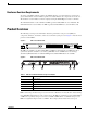
Removing and Installing a PRP Figure 6 CONNECTOR CLASS 1 LASER LASERPRODUKT PRODUCT PRODUIT LASER DER KLASSE 1 DE CLASSE 1 PRODUCTO LASER DE CLASSE 1 TX 0 1 RX 2 3 ACTIVE UP CARRIER SIG BITS 0 ACT ACT K LIN K DAT A LIN DAT A ETH 1 SIG RX PKT ETH 0 40C48/POS -SR-SC BITS 1 AUX CR IT 272389 CLEAN WITH ALCOHOL WIPES BEFORE CONNECTING Installed PRP-3 (Cisco 12404 Shown) RESET CONSOLE PERFORMANC E IC MA MI AL JO NO R R RP3 MBUS ALARM FAIL FABRIC ENABLE CONSOLI DATED 2 SWIT
Removing and Installing a PRP Step 4 If you are replacing a PRP, disconnect any devices that are attached to the Ethernet, console, or auxiliary ports. If you are removing a PRP for maintenance and will reinstall the same one, you can leave the devices attached, provided that doing so will not strain the cables. Step 5 Using a 3/16-inch flat-blade screwdriver, loosen the two captive screws on the ends of the PRP.
Checking the Installation Step 8 If you disconnected cables to remove the PRP, or if you are installing a new PRP, reconnect the cables to the appropriate ports. (See the “Checking the Installation” section on page 23.) Step 9 Ensure that the console terminal is turned on. Step 10 Turn on system power. Step 11 Attach the network end of your RJ-45 cable to your transceiver, switch, hub, repeater, DTE, or other external equipment. Be sure to use the appropriate strain relief on cable connections.
Checking the Installation For AC-input power supplies, the green AC OK LED should go on. For DC-input power supplies, the green input OK LED should go on. For both types of power supplies, the output fail LED should be off. Step 2 Listen for the system blower modules or fan trays in the router; you should immediately hear them operating. In a noisy environment, place your hand in front of the exhaust vents to verify that the blower modules are operating.
Checking the Installation 1. The version of microcode running on your PRP might be different. PRP-3 ALphanumeric LEDs The following section discusses the alphanumeric LED messages and the console output displayed in sequence for a single PRP-3 and for dual PRP-3s. The alphanumeric LED messages help in identifying the state of the route processor and accordingly troubleshooting the problems faced.
Checking the Installation LED Display Description or Console Message RUN/IOX Displays “RP/0/2/CPU0:Sep 10 15:56:29.018: syslogd_helper: [84]: dsc_event_handler: Got SysMgr dSC event : 1 RP/0/2/CPU0:Jan 1 00:00:04.809 : mbus-prp3[58]: mbus-prp3: mbus_platform_init() failed (0x6). RP/0/2/CPU0:Sep 10 15:56:07.015 : dumper[53]: No HDD Controller found by process dumper RP/0/2/CPU0:Sep 10 15:56:21.538 : sysmgr[85]: %OS-SYSMGR-5-NOTICE : Card is COLD started RP/0/2/CPU0:Sep 10 15:56:22.
Checking the Installation (c) (1) (ii) of the Rights in Technical Data and Computer Software clause at DFARS sec. 252.227-7013. cisco Systems, Inc. 170 West Tasman Drive San Jose, California 95134-1706 Cisco IOS XR Software for the Cisco XR PRP, Version 3.8.0.15I Copyright (c) 2008 by Cisco Systems, Inc. RP/0/2/CPU0:Sep 10 16:34:19.351: syslogd_helper: [84]: dsc_event_handler: Got SysMgr dSC event : 1 Tip The LED message “I404/MRAM” is displayed between RDY/RP and RUN/IOX alphanumeric messages.
Checking the Installation LED Display Description or Console Message RUN/MBI Displays “Copyright (c) 2008 by Cisco Systems, Inc.
Checking the Installation Step 5 Caution Caution If the ROM monitor prompt (Rommon>) appears, you must boot the Cisco IOS software image you want to use by entering the appropriate b command at the ROM monitor prompt: • b—Boots the default system software from onboard Flash memory (if it is present in onboard Flash memory) • b filename [host]—Boots the file filename from the server host using TFTP • b flash—Boots the first file in the Flash memory card in Flash card slot 0 To prevent system proble
Checking the Installation Verifying Interface Status The status LEDs on the PRP indicate system and PRP status, which Flash disk slot is active, which Ethernet connection is in use, and what is occurring on the Ethernet interface. This section provides functional descriptions of the status LEDs on the PRP-2 (Figure 9) and the processes you should observe.
Upgrading to the PRP Note The BITS feature is not supported in Release 3.8.0. • One auxiliary port (AUX) and one console port (CONSOLE) LED: – AUX—Used as a backup for the command outputs on the console. – CONSOLE—Used for configuring the router by connecting an RJ-45 cable to the console terminal. The router can be configured through the console terminal. Upgrading to the PRP This section details how to upgrade from the GRP to the PRP.
Upgrading to the PRP Image Version = Cisco Internetwork Operating System Software IOS (tm) GS Software (GSR-P-M), Version 12.0(26)S, EARLY DEPLOYMENT RELEASE SOFTWARE (fc1) TAC Support: http://www.cisco.com/tac Copyright (c) 1986-2003 by cisco Systems, Inc.
Upgrading to the PRP Step 5 Use the copy tftp: disk1: command to copy onto the Flash disk a PRP image that is the same as that currently running on the GRPs (in this example, 12.0(26)S). PRP images are titled c12kprp--.120-. You will receive an error that the PRP image is not executable on the GRP. When prompted to abort the copy, type n. Use the copy tftp: stby-disk1: command if the Flash disk is in the standby RP.
Upgrading to the PRP Note • Upgrading the RP ROM Monitor Using Cisco IOS Release 12.0(24)S or Later, page 34 • Upgrading the RP ROM Monitor Prior to Cisco IOS Release 12.0(24)S, page 35 The PRP-2 does not require an RP ROM monitor upgrade before Cisco IOS Software Release 12.0(30)S.
Upgrading to the PRP Step 8 Upgrade the ROM monitor image in RP1 using the upgrade rom-monitor slot sec-rp-slot command. If the routine finds that an upgrade is necessary, the new code will begin to be loaded. Once complete, reload the standby RP using the hw-module standby reload command. Upgrading the RP ROM Monitor Prior to Cisco IOS Release 12.0(24)S If your RPs are running a software image prior to Cisco IOS Release 12.
Upgrading to the PRP Upgrading to the PRP With Rebooting the Router If for any reason you cannot use High Availability, you should use the following procedure to upgrade from a GRP to a PRP. Step 1 Remove the Flash disk from the PRP card and install it into slot 1 of the active GRP. The following message will be displayed; do not format the disk. 22:21:31: %PCMCIAFS-5-DIBERR: PCMCIA disk 1 is formatted from a different router or PC.
Upgrading to the PRP Step 13 Connect the Ethernet and console cables to the PRP. Step 14 Remove the Flash disk from slot1: on the GRP and insert the Flash disk into slot0: on the PRP. Step 15 Boot the router. Step 16 The router will come up with no configuration and prompt you to enter the Initial Configuration menu. Abort the Initial Configuration options by entering no when prompted.
Upgrading to the PRP Step 23 The router will now boot with the correct configuration as was previously running on the GRP. Perform any post-boot checks: verify that the line cards have booted, required interfaces are active, CEF is operational, IGP adjacencies have formed, and the BGP peerings are established. Differentiating Between PRP-1 and PRP-2 You can use the software to determine whether you have installed a PRP-1 or a PRP-2.
Upgrading to the PRP • Turboboot Approach • Pre-Staging Approach Turboboot Approach You can upgrade PRP-1 or PRP-2 with Cisco IOS XR software installed to PRP-3 using route processor failover (RPFO). RPFO helps to minimize downtime and ensures service availability. To support RPFO the PRP-1 or PRP-2 must have Cisco IO S XR Software Release 3.8.0 or a later release, which supports PRP-3.
Upgrading to the PRP Pre-Staging Approach In a pre-staging approach the PRP-3 is loaded with the necessary Cisco IOS XR Software Release 3.8.0 software image, optional PIEs, and SMUs in a standalone chassis. After PRP-3 is in working condition, insert into PRP-2 chassis. To upgrade PRP-1 or PRP-2 with Cisco IOS XR software to PRP-3, perform the following steps: Step 1 Turboboot PRP-3 in a standalone chassis. Step 2 Install the necessary PIEs, SMUs on the PRP-3.
Configuring Interfaces on the PRP Step 5 Insert the PRP-3 into the Cisco XR 12000 Series Router chassis. Step 6 Turboboot the PRP-3 as indicated in section Turboboot Approach, page 39. Step 7 After PRP-3 finishes loading Cisco IOS XR Software image, load the converted Cisco IOS XR Software configuration. Step 8 Verify that all configurations are properly configured on PRP-3 and if the traffic has resumed.
Configuring Interfaces on the PRP Ethernet Interface Receptacles, Cables, and Pinouts There are two RJ-45 Ethernet interface receptacles on the PRP and one RJ-45 Gigabit Ethernet interface receptacle on the PRP-2, providing media-dependent interface (MDI) Ethernet ports. These connections support IEEE 802.3 and IEEE 802.3u interfaces compliant with 10BASE-T and 100BASE-TX standards. The transmission speed of the Ethernet ports is auto-sensing by default and is user configurable.
Configuring Interfaces on the PRP Straight-Through Cable Pinout (Connecting MDI Ethernet Port to MDI-X Wiring) MDI wiring MDI-X wiring 1 TxD+ 1 RxD+ 2 TxD– 2 RxD– 3 RxD+ 3 TxD+ 6 RxD– 6 TxD– Crossover Cable Pinout (for Connecting Two PRPs) PRP PRP 1 TxD+ 1 TxD+ 2 TxD– 2 TxD– 3 RxD+ 3 RxD+ 6 RxD– 6 RxD– 75431 Figure 13 H11007 Figure 12 Table 11 lists the cabling specifications for 100-Mbps transmission over unshielded twisted-pair (UTP) cables.
Configuring Interfaces on the PRP Ethernet Interface Cable Connection Procedure The RJ-45 receptacles on the PRP-1 provide two physical connection options for Ethernet interfaces and three physical connections on the PRP-2. RJ-45 cables are not available from Cisco Systems; they are available from commercial cable vendors. To connect cables to the PRP Ethernet interfaces (ports labeled ETH0, ETH1 and ETH2; see Figure 9), attach the Category 5 UTP cable directly to an RJ-45 receptacle on the PRP.
Configuring Interfaces on the PRP Configuring the Ethernet Interfaces The IEEE 802.3 Ethernet interfaces, located on the PRP, allow connections to external Ethernet networks and are capable of data transmission rates of 10 Mbps and 100 Mbps. The transmission speed of the Ethernet ports is auto-sensing by default and is user configurable.
Configuring Interfaces on the PRP Using the Setup Command Facility to Configure an Ethernet Interface In the following example of an Ethernet configuration using the setup command facility, the Ethernet interface is configured using IP and Connectionless Network Service (CLNS). In this example, you should use IP, CLNS, and the default RJ-45 Ethernet connection.
Configuring Interfaces on the PRP Figure 15 Console and Auxiliary Port Connections K EN LIN ETH 0 PRIMARY -1 OT SL 0 OT SL 1 K EN LIN ETH 1 PRIMARY RX TX 3 RX AUX CONSOLE 5 70692 TX 4 2 Note 1 Modem 4 Auxiliary port 2 Console terminal 5 Console port 3 RJ-45 Ethernet cables — The console and auxiliary ports are both asynchronous serial ports; any devices connected to these ports must be capable of asynchronous transmission.
Configuring Interfaces on the PRP-3 Configuring the Auxiliary Interface The auxiliary port on the PRP is a DTE, RJ-45 plug for connecting a modem or other DCE device (such as a CSU/DSU or another router) to the router. The port is labeled Aux, as shown in Figure 15. The asynchronous auxiliary port supports hardware flow control and modem control. Table 14 lists the pinout for this port.
Configuring Interfaces on the PRP-3 DETAILED STEPS Step 1 Step 2 Command or Action Purpose Identify the active RP or DRP. Identifies the RP or DRP to which you must connect in the next step. Connect a terminal to the Console port of the active RP or DRP. • This step is not required when the router hosts only one RP. • On a Cisco CRS-1 router, the active RP or DRP is identified by a lighted Primary LED on the RP front panel.
Configuring Interfaces on the PRP-3 Establishing a Connection Through a Terminal Server A terminal server connection provides a way to access the Console port from a remote location. It is less expensive to connect to the router through the Management Ethernet interface (because you do not have the additional cost of a terminal server). However, if you need to perform tasks that require Console port access from a remote location, a terminal server is the best connection method.
Configuring Interfaces on the PRP-3 DETAILED STEPS Step 1 Step 2 Command or Action Purpose Install and configure the terminal server. Prepares the terminal server for communications with the router and with Telnet clients. Connect the terminal server to the Console port of the target RP or DRP. • This step is usually preformed once. • For router access, users need the Telnet server IP address and port number for each RP they access.
Configuring Interfaces on the PRP-3 Step 6 Command or Action Purpose Press Enter. (Optional) Initiates communications with the RP or DRP. • If no text or router prompt appears when you start the Telnet session, press Enter to initiate communications. • If the router has no configuration, the router displays the prompt: Enter root-system username: Enter the root-system username and password when prompted.
Configuring Interfaces on the PRP-3 When you log in, the username and password may be validated by any of the following services: • Usernames configured on the router (username command in global configuration mode) • Root-system usernames configured on the owner SDR • Passwords configured for the router console and auxiliary ports (password or secret command in line configuration mode) • A RADIUS server • A TACACS+ server The username and password validation method that your router uses is determ
Configuring Interfaces on the PRP-3 Table 15 CLI Prompt Description (Continued) Prompt Syntax Components Description slot Slot in which the RP or DRP is installed. In a Cisco CRS-1 router, the RP physical slot number is “RP0” or “RP1.” In a Cisco XR 12000 Series Router, the physical slot number can be 0 to 15, and there can be multiple SDRs, each of which is represented by an RP. module Entity on a card that executes user commands or communicates with a port (interface).
Configuring Interfaces on the PRP-3 Table 16 Management Ethernet Interface Name Syntax Description (Continued) Syntax Components Description module On an RP, the module is “CPU0.” DRPs have two processors, so the module is either “CPU0” and “CPU1.” port On Cisco XR 12000 Series Routers, there are three Ethernet ports on PRP-2 cards. The Ethernet ports are labeled ETH 0, ETH 1, and ETH 2. For the ETH 0 port, specify 0, for the ETH 1 port, specify 1, and for the ETH 2 port, specify 2.
Configuring Interfaces on the PRP-3 Configuring the Management Ethernet Interface To use the Management Ethernet interface for system management and remote communication, you must configure an IP address and a subnet mask for the interface. If you want the interface to communicate with devices on other networks (such as remote management stations or TFTP servers), you need to configure a default route for the router.
Configuring Interfaces on the PRP-3 DETAILED STEPS Step 1 Command or Action Purpose configure Enters global configuration mode. Example: RP/0/RP0/CPU0:router# configure Step 2 interface MgmtEthrack/slot/CPU0/port Example: Enters interface configuration mode and specifies the Management Ethernet interface of the primary RP.
Configuring Interfaces on the PRP-3 Step 8 Command or Action Purpose end Ends the configuration session and returns to EXEC mode. Example: RP/0/RP0/CPU0:router(config)# end Step 9 show interfaces MgmtEthrack/slot/CPU0/port Displays the interface details to verify the settings.
Additional Configuration and Maintenance Tasks Additional Configuration and Maintenance Tasks This section contains information on the following additional configuration, maintenance, and upgrade tasks: • Understanding the Cisco IOS Software Configuration Register, page 59 • Understanding the Cisco IOS XR Software Configuration Register, page 63 • Using Flash Disks in the PRP, page 67 • Removing and Installing a Compact Flash Disk, page 71 • Removing and Installing a Hard Disk Drive, page 72 • R
Additional Configuration and Maintenance Tasks The RP ROM monitor is loaded into the RP Flash ROM when the RP is manufactured. You can use it to boot the system from local Flash memory devices. The RP ROM monitor software can be upgraded in the field, if necessary. Note All PRP-2 cards shipped prior to the release of Cisco IOS release 12.0(30)S are provided with a ROM monitor version installed at the factory. This ROM monitor version cannot be changed while using IOS images older than 12.0(30)S.
Additional Configuration and Maintenance Tasks Boot Field Settings Bits 00 to 03 of the software configuration register are referred to as the boot field, which defines a source for booting the default Cisco IOS software image required to run the router. The value of the boot field is specified as a binary number, as described in Table 19.
Additional Configuration and Maintenance Tasks Command Purpose Step 4 Router(config)# ctrl-Z Exits global configuration mode. Step 5 Router# show version Displays the software configuration register value currently in effect. This is the value that will be used the next time the router reloads.
Additional Configuration and Maintenance Tasks into ROM monitor mode. Regardless of the setting of the Break enable bit in the software configuration register, pressing the Break key during approximately the first 5 seconds of booting causes a return to the ROM monitor. Bit 9 is not used. Bit 10 of the software configuration register controls the host portion of the IP broadcast address.
Additional Configuration and Maintenance Tasks The following sections describes how to change the configuration register settings from EXEC mode and from the ROM monitor mode: • Commonly Used Configuration Register Value Settings • Changing the Configuration Register Settings from EXEC Mode • Changing the Configuration Register Settings from ROM Monitor Mode Commonly Used Configuration Register Value Settings To change the configuration register setting from normal operating mode, enter the config-re
Additional Configuration and Maintenance Tasks 8. reload DETAILED STEPS Command or Action Purpose Step 1 Connect a terminal to the primary RP Connects a terminal or PC to the primary RP console port and log in to the router. console port and logs in to the router Step 2 configure Enters global configuration mode.
Additional Configuration and Maintenance Tasks Step 7 Command or Action Purpose end Exits global configuration mode. Example: Router(config)# end Step 8 reload Reloads the system for the changes to take effect.
Additional Configuration and Maintenance Tasks DETAILED STEPS Step 1 Command or Action Purpose confreg value Sets the configuration register to the assigned value. Example: rommon1> confreg 0x2 • See the Commonly Used Configuration Register Value Settings section for more information. Caution Step 2 reset Resetting the configuration register may change the baud rate for the console. Reloads the system for the changes to take effect.
Additional Configuration and Maintenance Tasks Table 24 Supported Flash Disk Sizes and Product Numbers Flash Disk Size Product Number 64 MB MEM-12KRP-FD64= 128 MB MEM-12KRP-FD128= 255 MB MEM-12KRP-FD256= 1 GB MEM-12KRP-FD1G= Removing and Installing a Flash Disk in the PRP The PRP has two Flash disk slots into which you can install ATA Flash disks, linear Flash memory cards, or a combination of the two. Slot positions are labeled slot 0 and slot 1.
Additional Configuration and Maintenance Tasks Figure 17 Installing and Removing a Flash Disk T EC EJ OT SL 0 OT 1 ETH 0 SL ETH 1 K EN CONSOLE LIN PRIMARY K TX PERFORMANCE ROUTE PROCESSOR 1 (PRP-1) 75038 LIN TX T SE RE PRIMARY AUX RX RX EN Figure 18 PRP-3—Installing and Removing an External CompactFlash 272394 T EC EJ Installing a Flash Disk To install a flash disk, follow these steps: Step 1 Remove the flash disk slot cover by loosening the captive screw shown in Figure 16.
Additional Configuration and Maintenance Tasks Caution The Flash disk does not insert all the way inside the PRP; a portion of the card remains outside of the slot. Do not attempt to force the card past this point. Working with Flash Disks A Flash disk contains the Cisco IOS software image you need to boot your router. In some cases, you might need to insert a new Flash disk and copy images or backup configuration files onto it. Before you can use a new Flash disk, you must format it.
Additional Configuration and Maintenance Tasks Removing and Installing a Compact Flash Disk Note You must remove the PRP-2 before you can remove or install a compact flash disk. The compact flash disk is only supported on the PRP-2. To remove a compact flash disk (CF) from the PRP-2 board, follow these steps: Loosen the screw fastening the retaining bracket for the CF. (See Figure 19.
Additional Configuration and Maintenance Tasks Step 5 Swivel the retaining bracket back into place with the end of the bracket resting in the hole on the PRP-2 board. Step 6 Fasten the screw on the retaining bracket. Removing and Installing a Hard Disk Drive Note You must remove the PRP-3 or PRP-2 before you can remove or install a hard disk drive. The hard disk drive is only supported on the PRP-2.
Additional Configuration and Maintenance Tasks Installing the Hard Disk Drive 101107 T H 8 IS 0 S 0 ID -2 E 4 T 0 O 6 0 F A -0 C 1 E P R LA E T V E 3 __ H D -P R P 2- 40 G Figure 20 2 1 OL-17436-01 73
Additional Configuration and Maintenance Tasks Figure 21 PRP-3—Installing and Removing a Hard Drive 272393 3 2 1 Step 2 1 Screw receptor on a PRP-3 or PRP-2 board 2 Guide pin on PRP-3 or PRP-2 board 3 Screw to fasten HDD to PRP-3 or PRP-2 board Tighten all four of the screws on the HDD into the PRP-3 or PRP-2 board. Recovering a Lost Password For IOS This section provides information on how to recover a lost password. The following overview describes this process: 74 1.
Additional Configuration and Maintenance Tasks Note A key to recovering a lost password is to set the configuration register so that the contents of NVRAM are ignored (0x0040), allowing you to see your password. 4. Enter privileged level in the system EXEC. 5. Use the show startup-config command to display the enable password. 6. Change the configuration register value back to its original setting.
Additional Configuration and Maintenance Tasks You must reset or power cycle for the new config to take effect Step 7 Initialize the router by entering the i command as follows: Rommon 1> i The router power cycles, the configuration register is set to ignore the configuration file, and the router boots the boot system image and prompts you with the system configuration dialog as follows: --- System Configuration Dialog --- Step 8 Enter no in response to the system configuration dialog prompts until th
Additional Configuration and Maintenance Tasks Recovering the Root Password on Single-RP Routers Use the following procedure to recover the router password from a router with a single RP. Step 1 Place the router in ROM Monitor mode. Step 2 Set the RP configuration register to 0x42 at the ROMMON prompt: rommon 1 > confreg 0x42 Note Step 3 The configuration register is not an environment variable like TURBOBOOT (which is described earlier in this chapter).
Additional Configuration and Maintenance Tasks Step 3 Set the active RP configuration register to 0x42: rommon 1 > confreg 0x42 Step 4 Reset or power cycle the router so that the new setting can take effect: rommon 2 > reset Step 5 Press Return at the prompt to enter the password recovery dialog. Then enter the new root-system username and password and save the configuration, as shown in the following example: router con0/0/CPU0 is now available Press RETURN to get started.
Additional Configuration and Maintenance Tasks Figure 22 Locations of PRP Components and Memory 1 3 2 1 OTSL 0 OTSL ETH 0 6 CONSOLE TX K LIN T 5 AUX RX EN PRIMARY SE 4 ETH 1 RX TX EN K LIN RE PRIMARY 7 8 PERFORMANCE ROUTE PROCESSOR 1 (PRP-1) 9 10 1 Backplane connector 6 Ethernet ports 2 Flash SIMM (Socket number P3) 7 Auxiliary port 3 SDRAM DIMMs Bank 1 - Socket number U15 Bank 2 - Socket number U18 8 Console port 4 Ejector lever 9 Handle 5 Flash disk slots 10 Disp
Additional Configuration and Maintenance Tasks . Table 27 Supported PRP-2 Route Memory Configurations Total Route Memory Cisco Product Number DIMM Modules SDRAM DIMM Sockets1 1 GB2 MEM-PRP2-1G 1 1-GB DIMM Bank 1 (U15) 2 GB MEM-PRP2-1G 1 2-GB DIMM Bank 1 (U15) 3 GB MEM-PRP2-3G 1 2-GB DIMM + Bank 1(U15) and Bank 2 (U18)3 1 1-GB DIMM 4 GB MEM-PRP2-4G 2 2-GB DIMMs Bank 1 (U15) and Bank 2 (U18) 1. Bank 1 (U15) must be populated first. 2.
Additional Configuration and Maintenance Tasks Table 28 Supported PRP-3 Route Memory Configurations Total Route Memory Cisco Product Number DIMM Modules SDRAM DIMM Sockets1 4 GB MEM-PRP3-4G= 2 2-GB DIMMs Bank 1 (U8) and Bank 2 (U10) 8 GB MEM-PRP3-8G= 2 4-GB DIMMs Bank 1 (U8) and Bank 2 (U10) 1. Bank 1 (U15) must be populated first. Caution Only memory approved by Cisco is supported. Both the DIMMs must be of the same size.
Additional Configuration and Maintenance Tasks Step 4 Use the socket release levers to eject the DIMM. • For a socket with dual release levers (see Figure 24), pull down both levers at the same time to eject the DIMM. or • For a socket with a single release lever (see Figure 25), pull the lever to eject the DIMM. Caution Handle the edges of the DIMM only. Do not touch the integrated circuit devices on the DIMM, the metal traces, or fingers, along the edge of the DIMM, or the pins in the DIMM socket.
Additional Configuration and Maintenance Tasks Handling a DIMM H6507 Figure 26 Key Caution When inserting DIMMs into a socket, apply firm, but not excessive, pressure. If you damage a DIMM socket, you must return the line card for repair. Step 6 Gently insert the DIMM into the socket and push until the DIMM snaps into place and the release lever is flush against the side of the socket. Step 7 Verify that the release lever is flush against the side of the socket.
Regulatory, Compliance, and Safety Information Step 3 Reinstall the PRP and perform another installation check. If the router fails to restart properly after several attempts and you are unable to resolve the problem, access Cisco.com or contact your Cisco service representative for assistance. Before calling, however, make note of any console error messages, unusual LED states, or other router indications or behaviors that might help to resolve the problem.
Regulatory, Compliance, and Safety Information • Move the equipment farther away from the television or radio. • Plug the equipment into an outlet that is on a different circuit from the television or radio. (That is, make certain the equipment and the television or radio are on circuits controlled by different circuit breakers or fuses.) CISPR 22 This apparatus complies with CISPR 22/EN55022 Class B radiated and conducted emissions requirements.
Regulatory, Compliance, and Safety Information Class A Notice for Taiwan and Other Traditional Chinese Markets Warning This is a Class A Information Product, when used in residential environment, it may cause radio frequency interference, under such circumstances, the user may be requested to take appropriate countermeasures.
Regulatory, Compliance, and Safety Information This document is to be used in conjunction with the installation and configuration guide for your Cisco XR 12000 Series Router.
Regulatory, Compliance, and Safety Information 88 OL-17436-01