
Data Sheet

Description
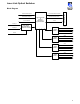
In the event of a primary optical path failure, the
optical switch protects fiber transmission links by
toggling to a redundant path. The switch position
is determined by an input TTL voltage, ROSA /
TNCS element management system, or by a
manual rocker switch located on the front panel.
The unit was designed to accept the TTL voltage
from other Laser Link products, such as receivers
or EDFAs.
Up to four individual optical switch components may be housed in and supported by a single one rack unit
chassis.
Features
• Accepts switch state determining logic from other Laser Link devices
• Allows for efficient use of space, single RU chassis supports up to 4 switch components
• Primary and redundant powering options (AC or DC)
• Configurable to house 1-4 switches in single RU chassis
• Front panel LEDs indicate switch position(s)
• TTL outputs provide voltages indicating switch position for external alarming
• Operates in remote or local mode
• Rear accessible, RJ-11 input and output jacks for ROSA / TNCS element management system interface
Optoelectronics
Laser Link
®
Optical Switches