
Getting Started Guide

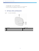
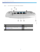

Table Of Contents
- Cisco Catalyst 9136I Series Access Points
- 1 About this Guide
- 2 About the Cisco Catalyst 9136I Series Wireless Access Point
- 3 Safety Instructions
- 4 Unpacking
- 5 AP Views, Ports, and Connectors
- 6 Preparing the AP for Installation
- 7 Installation Overview
- 8 Performing a Pre-Installation Configuration
- 9 Mounting the Access Point
- 10 Powering the Access Point
- 11 Configuring and Deploying the Access Point
- 12 Checking the Access Point LEDs
- 13 Miscellaneous Usage and Configuration Guidelines
- 14 FAQs
- 15 Related Documentation
- 16 Declarations of Conformity and Regulatory Information
- Manufacturers Federal Communication Commission Declaration of Conformity Statement
- VCCI Statement for Japan
- Guidelines for Operating Cisco Catalyst Access Points in Japan
- Statement 371—Power Cable and AC Adapter
- Industry Canada
- Canadian Compliance Statement
- Declaration of Conformity for RF Exposure
- Generic Discussion on RF Exposure
- This Device Meets International Guidelines for Exposure to Radio Waves
- This Device Meets FCC Guidelines for Exposure to Radio Waves
- This Device Meets the Industry Canada Guidelines for Exposure to Radio Waves
- Cet appareil est conforme aux directives internationales en matière d'exposition aux fréquences radioélectriques
- Additional Information on RF Exposure
- Administrative Rules for Cisco Catalyst Access Points in Taiwan
- Low-power Radio-frequency Devices Technical Specifications Operation of Cisco Catalyst Access Points in Brazil
- Declaration of Conformity Statements
- Communications, Services, and Additional Information
- Cisco Bug Search Tool

10
Cisco Catalyst 9136I Series Access Points
6 Preparing the AP for Installation
Before you mount and deploy your access point, we recommend that you perform a site survey (or use the site planning
tool) to determine the best location to install your access point.
You should have the following information about your wireless network available:
Access point locations.
Access point mounting options: below a suspended ceiling, on a flat horizontal surface, or on a desk top.
Note You can mount the access point above a suspended ceiling but you must purchase additional mounting
hardware: See “Mounting the Access Point” section on page 13 for additional information.
Access point power options: Use Cisco power injector—Cisco Power Injector AIR-PWRINJ7= or UL approved Listed
Power Adapter—802.3at (PoE+) 802.3af, or Cisco Universal PoE (Cisco UPOE).
Note Use an UL listed power adapter with rated output 42.5-57 Vdc, min. 1.11A, Tma is 50 degree C minimum,
Altitude is 3048m minimum.
Note The UL approved Listed Power Adapter must meet the following minimum specifications: Rated output of
42.5-57 Vdc, min. 1.11A, Tma is 50°C minimum, Altitude is 3048m minimum.
Note If 802.3af is used, both the 2.4 GHz and 5 GHz radios will be reduced to 1x1 and Ethernet will be
downgraded to 1 GbE. The USB port will also be off.
Operating temperature:
— C9136I: 32°—122°F (0°—50°C)
Note When installing the C9136I in an environment where the ambient temperature is in the range of
104
°—122°F (>40°—50°C), the access point configuration will change from 8x8 to 4x4 on the 5 GHz
radios and the uplink Ethernet will downgrade to 1GbE. However, the USB port will remain enabled.
Cisco recommends that you make a site map showing access point locations so that you can record the device MAC
addresses from each location and return them to the person who is planning or managing your wireless network.
7 Installation Overview
Installing the access point involves these operations:
Step 1 Performing a Pre-Installation Configuration, page 11 (optional)
Step 2 Preparing the AP for Installation, page 10
Step 3 Mounting the Access Point, page 13
Step 4 Powering the Access Point, page 15