
Getting Started Guide

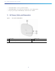
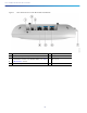

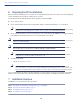
Table Of Contents
- Cisco Catalyst 9136I Series Access Points
- 1 About this Guide
- 2 About the Cisco Catalyst 9136I Series Wireless Access Point
- 3 Safety Instructions
- 4 Unpacking
- 5 AP Views, Ports, and Connectors
- 6 Preparing the AP for Installation
- 7 Installation Overview
- 8 Performing a Pre-Installation Configuration
- 9 Mounting the Access Point
- 10 Powering the Access Point
- 11 Configuring and Deploying the Access Point
- 12 Checking the Access Point LEDs
- 13 Miscellaneous Usage and Configuration Guidelines
- 14 FAQs
- 15 Related Documentation
- 16 Declarations of Conformity and Regulatory Information
- Manufacturers Federal Communication Commission Declaration of Conformity Statement
- VCCI Statement for Japan
- Guidelines for Operating Cisco Catalyst Access Points in Japan
- Statement 371—Power Cable and AC Adapter
- Industry Canada
- Canadian Compliance Statement
- Declaration of Conformity for RF Exposure
- Generic Discussion on RF Exposure
- This Device Meets International Guidelines for Exposure to Radio Waves
- This Device Meets FCC Guidelines for Exposure to Radio Waves
- This Device Meets the Industry Canada Guidelines for Exposure to Radio Waves
- Cet appareil est conforme aux directives internationales en matière d'exposition aux fréquences radioélectriques
- Additional Information on RF Exposure
- Administrative Rules for Cisco Catalyst Access Points in Taiwan
- Low-power Radio-frequency Devices Technical Specifications Operation of Cisco Catalyst Access Points in Brazil
- Declaration of Conformity Statements
- Communications, Services, and Additional Information
- Cisco Bug Search Tool

5
Cisco Catalyst 9136I Series Access Points
Antennas and Radios
The C9136I series access point configurations are:
C9136I-x
Internal Antennas
The C9136I models (C9136I-x) have four internal dual-band antennas with a dedicated 2.4 GHz radio and a 5 GHz radio,
four internal single-band antennas with a dedicated 5 GHz radio, four internal single-band antennas with a dedicated
6-GHz radio, one internal single-band antenna with a dedicated 2.4 GHz IOT radio, and one dual-band antenna with a
dedicated 2.4-GHz radio and a 5-GHz AUX radio and two tri-band antenna with a dedicated 2.4-GHz, 5-GHz and 6-GHz
Aux radio.
Operating Frequency and Maximum Output Power
3 Safety Instructions
Translated versions of the following safety warnings are provided in the translated safety warnings document that is
shipped with your access point. The translated warnings are also in the Translated Safety Warnings for Cisco Catalyst
Access Points, which is available on Cisco.com.
Warning
This unit is intended for installation in restricted access areas. A restricted access area can be
accessed by skilled, instructed or qualified personnel.
Statement 1017
Warning
IMPORTANT SAFETY INSTRUCTIONS
This warning symbol means danger. You are in a situation that could cause bodily injury. Before you
work on any equipment, be aware of the hazards involved with electrical circuitry and be familiar with
standard practices for preventing accidents. Use the statement number provided at the end of each
warning to locate its translation in the translated safety warnings that accompanied this device.
SAVE THESE INSTRUCTIONS
Statement 1071
Warning
Read the installation instructions before using, installing or connecting the system to the power source.
Statement 1004
Radio Frequency Bands Maximum Power level(dBm)
Wi-Fi 2400-2483.5 MHz 20
5150-5350 MHz 23
5470-5725 MHz 30
5925-6425 MHz 23
Bluetooth 2.4 GHz 20