Spec Sheet Cisco UCS C220 M3 High-Density Rack Server (Small Form Factor Disk Drive Model) CISCO SYSTEMS 170 WEST TASMAN DR SAN JOSE, CA, 95134 WWW.CISCO.COM PUBLICATION HISTORY REV D.
OVERVIEW . . . . . . . . . . . . . . . . . . . . . . . . . . . . . . . . . . . . . . . . . . . . . . . 5 DETAILED VIEWS . . . . . . . . . . . . . . . . . . . . . . . . . . . . . . . . . . . . . . . . . . . 6 Chassis Front View . . . . . . . . . . . . . . . . . . . . . . . . . . . . . . . . . . . . . . . . . . . . . . . . . . .6 Chassis Rear View . . . . . . . . . . . . . . . . . . . . . . . . . . . . . . . . . . . . . . . . . . . . . . . . . . .7 BASE SERVER STANDARD CAPABILITIES and FEATURES . . . . . . .
CONTENTS Power Specifications . . . . . . . . . . . . . . . . . . . . . . . . . . . . . . . . . . . . . . . . . . . . . . . . 79 Environmental Specifications . . . . . . . . . . . . . . . . . . . . . . . . . . . . . . . . . . . . . . . . . . . 82 Compliance Requirements . . . . . . . . . . . . . . . . . . . . . . . . . . . . . . . . . . . . . . . . . . . . .
Cisco UCS C220 M3 High-Density Rack Server (Small Form Factor Disk Drive Model)
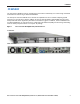
OVERVIEW OVERVIEW The Cisco® UCS C220 M3 rack server is designed for performance and density over a wide range of business workloads from web serving to distributed database. The enterprise-class UCS C220 M3 server extends the capabilities of Cisco’s Unified Computing System portfolio in a 1U form factor with the addition of the Intel Xeon E5-2600 v2 and E5-2600 series processor family CPUs that deliver significant performance and efficiency gains.
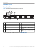
DETAILED VIEWS DETAILED VIEWS Chassis Front View Figure 2 shows the Cisco UCS C220 M3 High-Density SFF Rack Server.
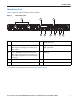
DETAILED VIEWS Chassis Rear View Figure 3 shows the external features of the rear panel.
BASE SERVER STANDARD CAPABILITIES and FEATURES BASE SERVER STANDARD CAPABILITIES and FEATURES Table 1 lists the capabilities and features of the base server. Details about how to configure the server for a particular feature or capability (for example, number of processors, disk drives, or amount of memory) are provided in CONFIGURING the SERVER, page 11.
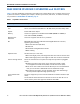
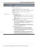
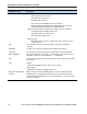
BASE SERVER STANDARD CAPABILITIES and FEATURES Capability/Feature Video Description The Emulex Pilot 3 Integrated Baseboard Management Controller provides video: ■ Matrox G200e video controller ■ Integrated 2D graphics core with hardware acceleration ■ Storage controller Supports all display resolutions up to 1920 x 1200 x 16 bpp resolution at 60 Hz ■ 24-bit color depth for all resolutions less than 1600x1200 ■ 8 MB video memory ■ Embedded RAID (3 Gbs) • Embedded SATA-only RAID controller, sup
BASE SERVER STANDARD CAPABILITIES and FEATURES Capability/Feature Description Interfaces ■ Rear panel • One RJ45 serial port connector • Two USB 2.
CONFIGURING the SERVER CONFIGURING the SERVER Follow these steps to configure the Cisco UCS C220 M3 High-Density SFF Rack Server: ■ STEP 1 VERIFY SERVER SKU, page 12 ■ STEP 2 SELECT CPU(s), page 13 ■ STEP 3 SELECT MEMORY, page 16 ■ STEP 4 SELECT RAID CONFIGURATION, page 22 ■ STEP 5 SELECT HARD DISK DRIVES (HDDs) or SOLID STATE DRIVES (SSDs), page 29 ■ STEP 6 SELECT PCIe OPTION CARD(s), page 31 ■ STEP 7 ORDER OPTIONAL NETWORK CARD ACCESSORIES, page 33 ■ STEP 8 ORDER POWER SUPPLY, page 38 ■
CONFIGURING the SERVER STEP 1 VERIFY SERVER SKU Verify the product ID (PID) of the server as shown in Table 2.
CONFIGURING the SERVER STEP 2 SELECT CPU(s) The standard CPU features are: ■ Intel Xeon E5-2600 v2 and E5-2600 series processor family CPUs (see the following link for instructions on how to upgrade your server from Intel Xeon E5-2600 to Intel Xeon E5-2600 v2 CPUs: http://preview.cisco.com/en/US/docs/unified_computing/ucs/c/CPU/IVB/install/IVB-C.html ■ Intel C600 series chipset ■ Cache size of up to 30 MB Select CPUs The available CPUs are listed in Table 3.
CONFIGURING the SERVER Table 3 Available Intel CPUs: E5-2600 and E5-2600 v2 Series Processor Family CPUs (continued) Power (W) Cache Size (MB) Cores QPI Highest DDR3 DIMM Clock Support (MHz)1 2.90 135 20 8 8 GT/s 1600 E5-2680 2.70 130 20 8 8 GT/s 1600 UCS-CPU-E5-2670 E5-2670 2.60 115 20 8 8 GT/s 1600 UCS-CPU-E5-2667 E5-2667 2.90 130 15 6 8 GT/s 1600 UCS-CPU-E5-2665 E5-2665 2.40 115 20 8 8 GT/s 1600 UCS-CPU-E5-2660 E5-2660 2.
CONFIGURING the SERVER Approved Configurations (1) 1-CPU configurations: ■ Select any one CPU listed in Table 3. (2) 2-CPU Configurations: ■ Select two identical CPUs from any one of the rows of Table 3 on page 13. Caveats ■ You can select either one processor or two identical processors. ■ For optimal performance, select DIMMs with the highest clock speed for a given processor (see Table 3 on page 13).
CONFIGURING the SERVER STEP 3 SELECT MEMORY The standard memory features are: ■ ■ Figure 4 16 DIMMs — Clock speed: 1866, 1600, or 1333 MHz — Ranks per DIMM: 1, 2, or 4 — Operational voltage: 1.5 V or 1.35 V — Registered or unbuffered ECC DDR3 DIMMs (RDIMMs or UDIMMs) or load-reduced DIMMs (LRDIMMs) Memory is organized with four memory channels per CPU, with up to two DIMMs per channel, as shown in Figure 4.
CONFIGURING the SERVER Select DIMMs and Memory Mirroring Select the memory configuration and whether or not you want the memory mirroring option. The available memory DIMMs and mirroring option are listed in Table 4. NOTE: When memory mirroring is enabled, the memory subsystem simultaneously writes identical data to two channels. If a memory read from one of the channels returns incorrect data due to an uncorrectable memory error, the system automatically retrieves the data from the other channel.
CONFIGURING the SERVER Approved Configurations (1) 1-CPU configuration without memory mirroring: ■ Select from 1 to 8 DIMMs. Refer to Memory Population Rules, page 60, for more detailed information. (2) 1-CPU configuration with memory mirroring: ■ Select 2, 4, 6, or 8 identical DIMMs. The DIMMs will be placed by the factory as shown in the following table.
CONFIGURING the SERVER (4) 2-CPU configuration with memory mirroring: ■ Select 2, 4, 6, or 8 identical DIMMs per CPU. The DIMMs will be placed by the factory as shown in the following table.
CONFIGURING the SERVER Caveats ■ System speed is dependent on how many DIMMs are populated per channel. See Table 5 for details. Table 5 DIMM Memory Speeds 1333-MHz Capable CPU DIMM Speed 1600-MHz Capable CPU 1866-MHz Capable CPU LRDIMM RDIMM (DR, SR) LRDIMM RDIMM (DR, SR) LRDIMM RDIMM (DR, SR) Voltage Voltage Voltage Voltage Voltage Voltage DPC 1.3 V 1.5 V 1.3 V 1.5 V 1.3 V 1.5 V 1.3 V 1.5 V 1.3 V 1.5 V 1.3 V 1.
CONFIGURING the SERVER ■ By default, starting with UCSM 2.0.4, DIMMs run in memory performance mode (1.5v) by BIOS default, which yields faster memory speeds than when the BIOS is set for the memory to run in power-savings mode. Memory speed is dependent on factors such as: — CPU choice — DIMM choice — DIMM population (how many DIMMs per channel are populated) — BIOS setting. For the DIMMs to run in power-savings mode (1.
CONFIGURING the SERVER STEP 4 SELECT RAID CONFIGURATION NOTE: If you do not select a mezzanine card, a PCIe RAID controller, or one of the embedded RAID upgrade options, you will have an embedded SATA-only RAID controller that supports up to four SATA-only drives (RAID 0, 1, 10) NOTE: When creating a RAID volume, follow these guidelines: ■ Use the same capacity for each drive in the volume ■ Use either all SAS drives or all SATA drives ■ Use either all HDDs or all SSDs NOTE: The number of RAID grou
CONFIGURING the SERVER Select RAID Options Select one of the following (these choices are dependent on the number of CPUs installed): ■ One embedded RAID upgrade option for internal drives, or ■ One mezzanine RAID controller for internal drives, or ■ One RAID controller for external drives, or ■ One RAID controller for internal drives, or ■ One mezzanine RAID controller for internal drives and one RAID controller for external drives NOTE: For all valid combinations of embedded RAID, mezzanine RAID
CONFIGURING the SERVER Table 7 Available Mezzanine Card RAID Options (continued) Product ID (PID) PID Description UCSC-RAID-11-C220 Cisco UCSC RAID SAS 2008M-8i Mezzanine Card (RAID 0, 1, 5, 10, and 50 supported), operating at 6 Gbs. UCSC-RAID-MZ-220 ■ Supports up to eight internal SAS+SATA drives. SAS and SATA drives can be mixed.
CONFIGURING the SERVER Table 8 Available PCIe RAID Controller Options (continued) Product ID (PID) PID Description UCS-RAID-9285CV-E or LSI MegaRAID SAS 9285CV-8e or 9286CV-8e (RAID 0, 1, 5, 6, 10) UCS-RAID9286CV-8E ■ Supports from one to eight external SAS ports (up to 240 external drives). NOTE: For SAS 9285CV-8e or 9286CV-8e external drive enclosure support, see the compatibility list (enclosure section) at the following link: http://tinyurl.
CONFIGURING the SERVER Notes . . . 1. The SAS 9285CV-8e is compatible with PCI Express 2.0 x8 and the 9271-8i, 9271CV-8i, and 9286CV-8e are compatible with PCI Express 3.0 x8. NOTE: The 9266CV-8i and 9285CV-8e RAID controllers will reach end-of-life (EOL) in November, 2013. After then, they will no longer be available.
CONFIGURING the SERVER See Table 9 for a summary of the supported RAID configuration options.
CONFIGURING the SERVER Caveats ■ Note that only a single Cisco VIC card (the half-height Cisco VIC 1225 and 1285 PCIe card) is supported and it must be installed in the full-height PCIe slot (slot 1) on riser 1. So take this into account when populating RAID controller cards. ■ You can choose an optional RAID configuration (RAID 0, 1, 5, 6, or 10), which is preconfigured at the factory. The RAID level you choose must be an available RAID choice for the controller selected.
CONFIGURING the SERVER STEP 5 (SSDs) SELECT HARD DISK DRIVES (HDDs) or SOLID STATE DRIVES The standard disk drive features are: ■ 2.5-inch small form factor ■ Hot-pluggable ■ Sled-mounted Select Drives The available drives are listed in Table 10. Table 10 Available Hot-Pluggable Sled-Mounted HDDs and SSDs PID Description Drive Type Capacity UCS-HD600G15KS2-E 600 GB SAS 15K RPM SFF HDD SAS 600 GB UCS-HD450G15KS2-E 450 GB SAS 15K RPM SFF HDD SAS 450 GB UCS-HD12T10KS2-E 1.
CONFIGURING the SERVER NOTE: When creating a RAID volume, follow these guidelines: ■ Use the same capacity for each drive in the volume ■ Use either all SAS drives or all SATA drives ■ Use either all HDDs or all SSDs Approved Configurations (1) Onboard RAID, Mezzanine Cards, and all PCIe RAID Controllers ■ If you have not selected an onboard RAID upgrade option (ROM5 or ROM55), a mezzanine card, or a PCIe RAID controller for internal drives (LSI MegaRAID 9271-8i or 9271CV-8i), you may select up to 4
CONFIGURING the SERVER STEP 6 SELECT PCIe OPTION CARD(s) The standard PCie card offerings are: ■ Converged Network Adapters (CNAs) ■ Network Interface Cards (NICs) ■ Host Bus Adapters (HBAs) ■ UCS Storage Accelerators Select PCIe Option Cards The available PCIe option cards are listed in Table 11.
CONFIGURING the SERVER Table 11 Available PCIe Option Cards (continued) Product ID (PID) PID Description Card Height UCSC-PCIE-E16002 Emulex LPe16002-M6, 16Gb Fibre Channel HBA with SR Optics Half UCS Storage Accelerators UCSC-F-FIO-5200MP UCS 5200 GB Fusion ioMemory3 PX Performance line for C-Series Full UCSC-F-FIO-2600MP UCS 2600 GB Fusion ioMemory3 PX Performance line for C-Series Half UCSC-F-FIO-1300MP UCS 1300 GB Fusion ioMemory3 PX Performance line for C-Series Half UCSC-F-FIO-1000MP
CONFIGURING the SERVER — ■ ■ ■ If any of the Fusion ioDrive2 cards are installed, they must be plugged into slot 1. Note that only the Cisco UCS 3.0 TB MLC Fusion ioDrive2 and Cisco UCS 5200 GB Fusion ioMemory3 cards are full-height; all other Fusion io cards are half-height and therefore may need an adapter to hold them securely in the full-height slot.
CONFIGURING the SERVER STEP 7 ORDER OPTIONAL NETWORK CARD ACCESSORIES Copper twinax cables and SFP optical modules may be ordered to support the two-port network cards that are available with the server. Choose Optional Twinax Cables Table 12 lists the copper twinax cables available for the PCIe cards. You can choose cable lengths of 1, 3, 5, 7, or 10 meters.
CONFIGURING the SERVER Approved Configurations (1) Choose Up to Two SFP+ Modules for Each Network Card Ordered ■ You may choose one or two SFP+ optical modules cables for each compatible PCIe network card ordered. You would normally order two modules for connecting to the primary and redundant network switching equipment. With the SFP+ optical modules, you can use common fiber optic cables, widely available. See the Figure 5 on page 37 for typical SFP+ and twinax connections to the network cards.
CONFIGURING the SERVER Table 14 PCIe Card Compatibility Cisco SFP Modules Twinax Cables SFP-10G-SR DS-SFP-FC8G-SW PCIe Cards Converged Network Adapters (CNAs) UCSC-PCIE-BSFP (Broadcom 57712 Dual Port 10Gb SFP+ w/TOE iSCSI) UCSC-PCIE-CSC-02 (Cisco VIC 1225 Dual Port 10Gb SFP+ CNA) UCSC-PCIE-C10T-02 (Cisco VIC 1225T Dual Port 10GBaseT CNA) UCSC-PCIE-C40Q-02 (Cisco VIC 1285 Dual Port 40Gb QSFP CNA) UCSC-PCIE-C40Q-03 (Cisco VIC 1385 Dual Port 40Gb QSFP+ CNA w/RDMA) UCSC-PCIE-ESFP (Emulex OCe11102-FX dual-port
CONFIGURING the SERVER Table 14 PCIe Card Compatibility (continued) Cisco SFP Modules Twinax Cables SFP-10G-SR DS-SFP-FC8G-SW PCIe Cards N2XX-AQPCI05 (QLogic QLE2562 Dual Port 8Gb Fibre Channel HBA) UCSC-PCIE-Q2672 (Qlogic QLE2672-CSC, 16Gb Fibre Channel HBA with SR Optics) UCSC-PCIE-E16002 (Emulex LPe16002-M6, 16Gb Fibre Channel HBA with SR Optics) No Preinstalled - do not change SFP No Preinstalled - do not change SFP No Preinstalled - do not change SFP Notes . . . 1.
CONFIGURING the SERVER STEP 8 ORDER POWER SUPPLY The C220 M3 SFF server accommodates two power supplies. A lightly loaded server can operate from one 650 W power supply. A fully loaded server might need to be powered with two 450 W or two 650 W power supplies (see Table 15). NOTE: For configurations that use 130 W or 135 W CPUs, the minimum power supply required is 650 W (UCSC-PSU-650W). See STEP 2 SELECT CPU(s), page 13.
CONFIGURING the SERVER STEP 9 SELECT AC POWER CORD(s) Using Table 16, select the appropriate AC power cords. You can select a minimum of no power cords and a maximum of two. If you select the option R2XX-DMYMPWRCORD, no power cord is shipped with the server.
CONFIGURING the SERVER Table 16 Available Power Cords Product ID (PID) PID Description SFS-250V-10A-AR Power Cord, SFS, 250V, 10A, Argentina Images 2500 mm Cordset rating: 10 A, 250/500 V MAX Length: 8.
CONFIGURING the SERVER Table 16 Available Power Cords Product ID (PID) PID Description CAB-9K10A-IT Power Cord, 250VAC 10A CEI 23-16/VII Plug, Italy Images Cordset rating: 10 A, 250 V Length: 8 ft 2 in. (2.5 m) Connector C15M (EN60320/C15 ) 186575 Plug: I/3G (CEI 23-16) CAB-9K10A-SW Power Cord, 250VAC 10A MP232 Plug, Switzerland Cordset rating: 10 A, 250 V Length: 8 ft. 2 in (2.
CONFIGURING the SERVER STEP 10 ORDER OPTIONAL REVERSIBLE CABLE MANAGEMENT ARM The reversible cable management arm mounts on either the right or left slide rails at the rear of the server and is used for cable management. Use Table 17 to order a cable management arm.
CONFIGURING the SERVER STEP 11 ORDER A TRUSTED PLATFORM MODULE (OPTIONAL) Trusted Platform Module (TPM) is a computer chip (microcontroller) that can securely store artifacts used to authenticate the platform (server). These artifacts can include passwords, certificates, or encryption keys. A TPM can also be used to store platform measurements that help ensure that the platform remains trustworthy.
CONFIGURING the SERVER STEP 12 ORDER CISCO FLEXIBLE FLASH SD CARD MODULE (OPTIONAL) You can order either one or two 32 GB SD cards. See Figure 6 on page 57 for the location of the SD cards. There are two locations, SD1 and SD2.
CONFIGURING the SERVER STEP 13 ORDER OPTIONAL USB 2.0 DRIVE You can order one optional USB 2.0 drive. The USB drive ordering information is listed in Table 20. Table 20 USB 2.0 Drive Product ID (PID) PID Description UCS-USBFLSH-S-4GB 4GB Flash USB Drive (shorter length) for all servers except C260 See Figure 6 on page 57 for the location of the USB connector.
CONFIGURING the SERVER STEP 14 SELECT OPERATING SYSTEM AND VALUE-ADDED SOFTWARE Several operating systems and value-added software programs are available. Select as desired from Table 21.
CONFIGURING the SERVER Table 21 OSs and Value-Added Software (for 2-CPU servers) (continued) PID Description Product ID (PID) Red Hat Enterprise Linux RHEL-2S-1G-1A RHEL/2 Socket/1 Guest/1Yr Svcs Required RHEL-2S-1G-3A RHEL/2 Socket/1 Guest/3Yr Svcs Required RHEL-2S-4G-1A RHEL/2 Socket/4 Guest/1Yr Svcs Required RHEL-2S-4G-3A RHEL/2 Socket/4 Guest/3Yr Svcs Required RHEL-2S-UG-1A RHEL/2 Socket/U Guest/1Yr Svcs Required RHEL-2S-UG-3A RHEL/2 Socket/U Guest/3Yr Svcs Required RHEL-HA-2S-1A RHEL Op
CONFIGURING the SERVER Table 21 OSs and Value-Added Software (for 2-CPU servers) (continued) PID Description Product ID (PID) VMware 5 VMW-VS5-STD-1A VMware vSphere 5 Standard for 1 Processor, 1 Year, Support Rqd VMW-VS5-STD-2A VMware vSphere 5 Standard for 1 Processor, 2 Year, Support Rqd VMW-VS5-STD-3A VMware vSphere 5 Standard for 1 Processor, 3 Year, Support Rqd VMW-VS5-STD-4A VMware vSphere 5 Standard for 1 Processor, 4 Year, Support Rqd VMW-VS5-STD-5A VMware vSphere 5 Standard for 1 Proces
CONFIGURING the SERVER STEP 15 SELECT OPERATING SYSTEM MEDIA KIT Select the optional operating system media listed in Table 22.
CONFIGURING the SERVER STEP 16 SELECT SERVICE and SUPPORT LEVEL A variety of service options are available, as described in this section. Unified Computing Warranty, No Contract If you have noncritical implementations and choose to have no service contract, the following coverage is supplied: ■ Three-year parts coverage. ■ Next business day (NBD) onsite parts replacement eight hours a day, five days a week. ■ 90-day software warranty on media.
CONFIGURING the SERVER SMARTnet for UCS Hardware Only Service For faster parts replacement than is provided with the standard Cisco Unified Computing System warranty, Cisco offers the Cisco SMARTnet for UCS Hardware Only Service. You can choose from two levels of advanced onsite parts replacement coverage in as little as four hours. SMARTnet for UCS Hardware Only Service provides remote access any time to Cisco support professionals who can determine if a return materials authorization (RMA) is required.
CONFIGURING the SERVER See Table 25.
CONFIGURING the SERVER You can choose a service listed in Table 27.
CONFIGURING the SERVER Table 28 Drive Retention Service Options (continued) Service Description Service Program Name SMARTnet for UCS HW ONLY+Drive Retention UCS HW+DR Service Level GSP Service Level Product ID (PID) UCWD7 24x7x4 Onsite CON-UCWD7-C220M3SF UCWD5 8x5xNBD Onsite CON-UCWD5-C220M3SF For more service and support information, see the following URL: http://www.cisco.com/en/US/services/ps2961/ps10312/Unified_Computing_Services_Overview.
OPTIONAL STEP - ORDER RACK(s) OPTIONAL STEP - ORDER RACK(s) The optional R42610 rack is available from Cisco for the C-Series servers, including the C220 M3 SFF server. This rack is a standard 19-inch rack and can be ordered with a variety of options, as listed in Table 29. Racks are shipped separately from the C220 M3 SFF server.
OPTIONAL STEP - ORDER PDU OPTIONAL STEP - ORDER PDU An optional power distribution unit (PDU) is available from Cisco for the C-Series rack servers, including theC220 M3 server. This PDU is available in a zero rack unit (RU) style (see Table 29). Table 30 PDU Options Product ID (PID) PID Description RP208-30-2P-U-2 Zero RU PDU For more information about the PDU, see PDUs, page 76.
SUPPLEMENTAL MATERIAL SUPPLEMENTAL MATERIAL CHASSIS An internal view of the C220 M3 chassis with the top cover removed is shown in Figure 6.
SUPPLEMENTAL MATERIAL 7 CPUs and heatsinks (two) 16 Power supplies (two, hot-swappable access through rear panel) 8 Integrated RAID on motherboard, and mini-SAS connectors 17 RTC battery on motherboard 9 Mezzanine RAID card, mini-SAS connectors SAS1 and SAS2 18 Software RAID 5 header (RAID key). CPUs and DIMMs Physical Layout Each CPU has four DIMM channels: ■ CPU1 has channels A, B, C, and D ■ CPU2 has channels E, F, G, and H Each DIMM channel has two banks: bank 1 and bank 2.
SUPPLEMENTAL MATERIAL Figure 7 Physical Layout of CPU DIMM Channels and Banks C1 C2 D1 D2 CPU1 Front of Server B2 B1 A2 A1 G1 G2 H1 H2 F2 F1 E2 E1 331707 CPU2 Cisco UCS Cisco UCS C220 M3 High-Density Rack Server (Small Form Factor Disk Drive Model) 59
SUPPLEMENTAL MATERIAL Memory Population Rules When considering the memory configuration of your server, you should consider the following items: ■ ■ Each channel has two DIMM slots (for example, channel A = slots A1 and A2). — A channel can operate with one or two DIMMs installed. — If a channel has only one DIMM, populate slot 1 first (the blue slot). When both CPUs are installed, populate the DIMM slots of each CPU identically.
SUPPLEMENTAL MATERIAL DIMM Population Order Populate the DIMMs for a CPU according to Table 32. Table 32 DIMM Population Order per CPU DIMMs per CPU Populate CPU 1 Slots Populate CPU 2 Slots 1 A1 E1 2 A1, B1 E1, F1 3 A1, B1, C1 E1, F1, G1 4 A1, B1, C1, D1 E1, F1, G1, H1 61 A1, B1, C1, E1, F1, G1, A2, B2, C2 E2, F2, G2 A1, B1, C1, D1, E1, F1, G1, H1, A2, B2, C2, D2 E2, F2, G2, H2 8 Notes . . . 1.
SUPPLEMENTAL MATERIAL Recommended Memory Configuration This section explains the recommended DIMM population order rules for the C220 M3 server. ■ All DIMMs must be DDR3 DIMMs. ■ Do not mix: — DIMMs with different clock rates in a channel — RDIMMs and LRDIMMs — ECC and non-ECC DIMMs ■ There are blue and black DIMM slots. Populate blue slots first.
SUPPLEMENTAL MATERIAL Table 33 Recommended Memory Configurations for Intel Xeon E5-2600 v2 CPUs (with 1600- and 1866-MHz DIMMs)1 Total System Memory Size 512 GB CPU 1 DIMMs CPU 2 DIMMs Blue Slots Black Slots Blue Slots Black Slots Bank 1 Bank 2 Bank 1 Bank 2 (A1,B1, C1,D1) (A2,B2, C2,D2) (E1,F1, G1,H1) (E2,F2, G2,H2) 4x32 GB3 4x32 GB 4x32 GB 4x32 GB DIMM Max Speed (MHz) Total DIMMs 1866 16 Notes . . . 1. Rows marked in yellow indicate best performance. 2. 1866-MHz 4 GB DIMMs are not offered. 3.
SUPPLEMENTAL MATERIAL Table 34 Recommended Memory Configurations for Intel Xeon E5-2600 CPUs ( with 1600-MHz DIMMs)1 Total System Memory Size 512 GB CPU 1 DIMMs CPU 2 DIMMs Blue Black Slots Blue Slots Slots Bank 2 Bank 1 Bank 1 (A2,B2, C2,D2) (E1,F1, G1,H1) (A1,B1, C1,D1) Black Slots Bank 2 (E2,F2, G2,H2) DIMM Max Speed (MHz) Total DIMMs 4x32 GB 4x32 GB 1333 16 4x32 GB2 4x32 GB Notes . . . 1. Rows marked in yellow indicate best performance. 2.
SUPPLEMENTAL MATERIAL Additional DIMM Populations The list in Table 35 is not a complete list of all supported DIMM populations, but highlights common configuration options.
SUPPLEMENTAL MATERIAL Low-Voltage DIMM Considerations The C220 M3 server can be ordered with dual-voltage (1.5/1.35 V) DIMMs only. Note the following considerations: 66 ■ Low-voltage DIMMs within the server must have the identical manufacturer, type, speed, and size. ■ Low-voltage DIMMs and standard-voltage DIMMs can be mixed in the same server. Note that this causes the system BIOS to default to standard-voltage operation (Performance Mode).
SUPPLEMENTAL MATERIAL RAID Details The available RAID configurations are shown in this section. (1) 1-CPU Configurations Mezzanine cards are not supported for 1-CPU configurations, Therefore, only the following RAID controllers are supported for single-CPU configurations.
SUPPLEMENTAL MATERIAL RAID Option ROM (OPROM) Settings The server contains an Option ROM (OPROM) for the PCIe slots. The server has a finite amount of option ROM with which it can boot up devices. Go into the BIOS and disable the OPROM on the PCIe slots not used for booting so that resources are available for the slots that are used for booting. An example OPROM BIOS screen is shown in Figure 8.
SUPPLEMENTAL MATERIAL Serial Port Details The pinout details of the rear RJ-45 serial port connector are shown in Figure 9.
SUPPLEMENTAL MATERIAL Upgrade and Servicing-Related Parts This section lists the upgrade and servicing-related parts you may need during the life of your server. Some of these parts are configured with every server, and some may be ordered when needed or may be ordered and kept on hand as spares for future use. See Table 36. Table 36 Upgrade and Servicing-related Parts for UCS C220 M3 SFF Server Spare Product ID (PID) Description N20-BBLKD= 2.
SUPPLEMENTAL MATERIAL Table 36 Upgrade and Servicing-related Parts for UCS C220 M3 SFF Server Spare Product ID (PID) Description UCS-CPU-EP2-PNP= Pick n place CPU tools for M3/EP v2 12 core CPUs (Purple)8 UCS-CPU-GREASE2= Thermal grease-for 2 CPUs-only for C220/C240-Red tip syringe8 UCSX-HSCK= UCS Processor Heat Sink Cleaning Kit (when replacing a CPU)8 Notes . . . 1. This part is included/configured with your UCS server (in some cases, as determined by the configuration of your server). 2.
SUPPLEMENTAL MATERIAL CPU Removal and Installation (“pick n place”) Tool Set The Pick n Place tool set includes two tools: ■ Pick and pull cap tool - used to pull off the plastic protective cap covering an empty CPU socket and to remove or lift a CPU processor without touching it Pick and place tool - used to install a CPU in its socket without damage. Must be used each time a CPU is installed in a UCS “M3” server. ■ Instructions for using this tool set are found at the following link: http://www.cisco.
SUPPLEMENTAL MATERIAL CPU Heat Sink Cleaning Kit The cleaning kit is used to remove the existing thermal compound from the bottom of the heat sink during a CPU replacement process. Instructions for cleaning are found at the following link: http://www.cisco.com/en/US/docs/unified_computing/ucs/c/hw/C220/install/replace.html#wp1233864 NOTE: When you purchase a spare CPU, the CPU cleaning kit is included.
SUPPLEMENTAL MATERIAL RACKS The Cisco R42610 rack (see Figure 10) is certified for Cisco UCS installation at customer sites and is suitable for the following equipment: ■ Cisco UCS B-Series servers and fabric interconnects ■ Cisco UCS C-Series and select Nexus switches The rack is compatible with hardware designed for EIA-standard 19-inch racks. Rack specifications are listed in Table 37. Table 37 Cisco R42610 Rack Specifications Parameter Standard Rack Expansion Rack Dimensions (H x W x D) 78.
SUPPLEMENTAL MATERIAL Figure 10 Cisco R42610 Rack Front view - door closed Front view - door open Front view - door removed Cisco UCS Cisco UCS C220 M3 High-Density Rack Server (Small Form Factor Disk Drive Model) 75
SUPPLEMENTAL MATERIAL PDUs Cisco RP Series Power Distribution Units (PDUs) offer power distribution with branch circuit protection. Cisco RP Series PDU models distribute power to up to 24 outlets. The architecture organizes power distribution, simplifies cable management, and enables you to move, add, and change rack equipment without an electrician. With a Cisco RP Series PDU in the rack, you can replace up to two dozen input power cords with just one.
SUPPLEMENTAL MATERIAL KVM CABLE The KVM cable provides a connection into the server, providing a DB9 serial connector, a VGA connector for a monitor, and dual USB ports for a keyboard and mouse. With this cable, you can create a direct connection to the operating system and the BIOS running on the server. The KVM cable ordering information is listed in Table 38.
SUPPLEMENTAL MATERIAL Motherboard USB and SD Ports, and RAID Card Backup Location The C220 M3 SFF motherboard has a general-purpose USB socket, and two SD sockets as shown in Figure 13. The mounting location for the RAID SuperCap data cache power backup module is also shown.
TECHNICAL SPECIFICATIONS TECHNICAL SPECIFICATIONS Dimensions and Weight Table 39 UCS C220 M3 Dimensions and Weight Parameter Value Height 1.7 in. (4.32 cm) Width 16.92 in.(43.0 cm) Depth 28.5 in. (72.4cm) Front Clearance 3 in. (76 mm) Side Clearance 1 in. (25 mm) Rear Clearance 6 in. (152 mm) Weight Maximum (8 HDDs, 2 CPUs, 16 DIMMs, 2 power supplies) 35.6 lbs (16.2 kg) Minimum (1 HDD, 1 CPU, 1 DIMM, 1 power supply) 26.8 lbs (12.
TECHNICAL SPECIFICATIONS Table 40 UCS C220 M3 SFF 450 W Power Supply Specifications (continued) Description Specification Power supply output voltage Main power: 12 VDC Standby power: 12 VDC Power supply efficiency CSCI Platinum NOTE: AC input connector is an IEC 320 C-14 15A/250VAC power inlet. The general power specifications for the C220 M3 SFF server 650 W (AC) power supply are listed in Table 41.
TECHNICAL SPECIFICATIONS The general power specifications for the C220 M3 SFF server 930 W (DC) power supply are listed in Table 42 Table 42 UCS C240 M3 SFF Power Specifications 930 W DC power supply) Description Class Specification ■ RSP1 DC input voltage range ■ 40 to 72 VDC (self-ranging, 48 to 60 VDC nominal) DC line input current (steady state) ■ 23 A peak at 48 VDC 12 V main power output ■ 930 W 12 V standby power output ■ 30 W Power supply output voltage ■ Main power: 12 VDC ■ Sta
TECHNICAL SPECIFICATIONS Environmental Specifications The power specifications for the C220 M3 server are listed in Table 43. Table 43 UCS C220 M3 Environmental Specifications Parameter Minimum Temperature operating 41 to 104° F (5 to 40° C) derate the maximum temperature by 1°C per every 305m of altitude above sea level Temperature nonoperating –40 to 149°F (–40 to 65°C) Humidity (RH) nonoperating, non-condensing 10 to 90% Altitude operating 0 to 3,000 m (0 to 10,000 ft.
TECHNICAL SPECIFICATIONS Compliance Requirements The regulatory compliance requirements for C-Series servers are listed in Table 44. Table 44 UCS C-Series Regulatory Compliance Requirements Parameter Description Regulatory Compliance Products should comply with CE Markings per directives 2004/108/EC and 2006/95/EC Safety UL 60950-1 Second Edition CAN/CSA-C22.2 No.
TECHNICAL SPECIFICATIONS 84 Cisco UCS Cisco UCS C220 M3 High-Density Rack Server (Small Form Factor Disk Drive Model)