C H A P T E R 15 Performance Monitoring Note The terms "Unidirectional Path Switched Ring" and "UPSR" may appear in Cisco literature. These terms do not refer to using Cisco ONS 15xxx products in a unidirectional path switched ring configuration. Rather, these terms, as well as "Path Protected Mesh Network" and "PPMN," refer generally to Cisco's path protection feature, which may be used in any topological network configuration.
Chapter 15 Performance Monitoring 15.2 Intermediate-Path Performance Monitoring During the accumulation cycle, if the current value of a performance monitoring parameter reaches or exceeds its corresponding threshold value, a threshold crossing alert (TCA) is generated by the node and displayed by CTC. TCAs provide early detection of performance degradation. When a threshold is crossed, the node continues to count the errors during a given accumulation period.
Chapter 15 Performance Monitoring 15.3 Pointer Justification Count Performance Monitoring For detailed information about specific IPPM parameters, locate the card name in the following sections and review the appropriate definition. 15.3 Pointer Justification Count Performance Monitoring Pointers are used to compensate for frequency and phase variations. Pointer justification counts indicate timing errors on SDH networks. When a network is out of sync, jitter and wander occurs on the transported signal.
Chapter 15 Performance Monitoring 15.4.
Chapter 15 Performance Monitoring 15.4.1 E1-N-14 Card and E1-42 Card Performance Monitoring Parameters Table 15-2 Line PM Parameters for the E1-N-14 Card and E1-42 Card, Near-End Parameter Note Definition SDH path PMs do not increment unless IPPM is enabled. See the “15.2 Intermediate-Path Performance Monitoring” section on page 15-2. E1 CV-L Code Violation Line (CV-L) indicates the number of coding violations occurring on the line.
Chapter 15 Performance Monitoring 15.4.1 E1-N-14 Card and E1-42 Card Performance Monitoring Parameters Table 15-3 Transmit and Receive CEPT and CRC4 Framing Path PM Parameters for the Near-End and Far-End E1-N-14 Cards and E1-42 Cards (continued) Parameter Definition E1 (Tx or Rx) P-AISS AIS Seconds Path (P-AISS) is a count of one-second intervals containing one or more AIS defects.
Chapter 15 Performance Monitoring 15.4.2 E3-12 Card Performance Monitoring Parameters 15.4.2 E3-12 Card Performance Monitoring Parameters Figure 15-3 shows the signal types that support near-end and far-end PM parameters for the E3-12 card. Figure 15-4 shows where overhead bytes detected on the ASICs produce performance monitoring parameters for the E3-12 card.
Chapter 15 Performance Monitoring 15.4.2 E3-12 Card Performance Monitoring Parameters Table 15-5 Line PM Parameters for the Near-End E3-12 Card Parameter Definition E3 CV-L Code Violation Line (CV-L) indicates that the number of coding violations occurring on the line. This parameter is a count of BPVs and EXZs occurring over the accumulation period.
Chapter 15 Performance Monitoring 15.4.2 E3-12 Card Performance Monitoring Parameters Table 15-7 VC3 Low-Order Path PM Parameters for the Near-End and Far-End E3-12 Card (continued) Parameter Definition LP-UAS Low-Order Path Unavailable Seconds (LP-UAS) is a count of the seconds when the VC path was unavailable.
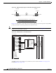
Chapter 15 Performance Monitoring 15.4.3 DS3i-N-12 Card Performance Monitoring Parameters 15.4.3 DS3i-N-12 Card Performance Monitoring Parameters Figure 15-5 shows the signal types that support near-end and far-end PM parameters for the DS3i-N-12 card. Figure 15-6 shows where overhead bytes detected on the ASICs produce performance monitoring parameters for the DS3i-N-12 card.
Chapter 15 Performance Monitoring 15.4.3 DS3i-N-12 Card Performance Monitoring Parameters The PM parameters for the DS3i-N-12 card are described in Table 15-9 through Table 15-14 on page 15-13. Table 15-9 Line PM Parameters for the Near-End DS3i-N-12 Card Parameter Definition DS3 CV-L Code Violation Line (CV-L) indicates that the number of coding violations occurring on the line. This parameter is a count of BPVs and EXZs occurring over the accumulation period.
Chapter 15 Performance Monitoring 15.4.3 DS3i-N-12 Card Performance Monitoring Parameters Table 15-11 CP-Bit Framing DS-3 Path PM Parameters for the Near-End DS3i-N-12 Card Parameter Definition DS3 CVCP-P Code Violation Path (CVCP-P) is a count of CP-bit parity errors occurring in the accumulation period. DS3 ESCP-P Errored Second Path (ESCP-P) is a count of seconds containing one or more CP-bit parity errors, one or more SEF defects, or one or more AIS defects.
Chapter 15 Performance Monitoring 15.4.3 DS3i-N-12 Card Performance Monitoring Parameters Table 15-13 VC3 Low-Order Path PM Parameters for the Near-End and Far-End DS3i-N-12 Cards Parameter Definition LP-EB Low-Order Path Errored Block (LP-EB) indicates that one or more bits are in error within a block. LP-BBE Low-Order Path Background Block Error (LP-BBE) is an errored block not occurring as part of an SES.
Chapter 15 Performance Monitoring 15.5 Performance Monitoring for Ethernet Cards Table 15-14 VC4 High-Order Path PM Parameters for the Near-End and Far-End DS3i-N-12 Cards (continued) Parameter Definition HP-ESR High-Order Path Errored Second Ratio (HP-ESR) is the ratio of errored seconds to total seconds in available time during a fixed measurement interval.
Chapter 15 Performance Monitoring 15.5.1 E-Series Ethernet Card Performance Monitoring Parameters Table 15-15 E-Series Ethernet Statistics Parameters (continued) Parameter Meaning Rx FCS Number of packets with a Frame Check Sequence (FCS) error. FCS errors indicate frame corruption during transmission. Rx Alignment Number of packets with alignment errors (received incomplete frames). Rx Runts Measures undersized packets with bad cyclic redundancy check (CRC) errors.
Chapter 15 Performance Monitoring 15.5.2 G-Series Ethernet Card Performance Monitoring Parameters Table 15-16 MaxBaseRate for STS Circuits STS maxBaseRate STS-1 51840000 STS-3c 155000000 STS-6c 311000000 STS-12c 622000000 Note Line utilization numbers express the average of ingress and egress traffic as a percentage of capacity. Note The E-Series Ethernet card is a Layer 2 device or switch and supports Trunk Utilization statistics.
Chapter 15 Performance Monitoring 15.5.2 G-Series Ethernet Card Performance Monitoring Parameters 15.5.2.1 G-Series Ethernet Statistics Window The Ethernet statistics window lists Ethernet parameters at the line level. The Statistics window provides buttons to change the statistical values shown. The Baseline button resets the displayed statistics values to zero. The Refresh button manually refreshes statistics. Auto-Refresh sets a time interval at which automatic refresh occurs.
Chapter 15 Performance Monitoring 15.5.2 G-Series Ethernet Card Performance Monitoring Parameters Table 15-18 G-Series Ethernet Statistics Parameters (continued) Note Parameter Meaning Rx Multicast Packets Number of multicast packets received since the last counter reset. Tx Multicast Packets Number of multicast packets transmitted. Rx Broadcast Packets Number of broadcast packets received since the last counter reset. Tx Broadcast Packets Number or broadcast packets transmitted.
Chapter 15 Performance Monitoring 15.5.3 ML-Series Ethernet Card Performance Monitoring Parameters Note Unlike the E-Series, the G Series card does not have a display of Trunk Utilization statistics, because the G-Series card is not a Layer 2 device or switch. 15.5.2.3 G-Series Ethernet History Window The Ethernet History window lists past Ethernet statistics for the previous time intervals.
Chapter 15 Performance Monitoring 15.5.3 ML-Series Ethernet Card Performance Monitoring Parameters Table 15-21 ML-Series Ether Ports PM Parameters (continued) Parameter Meaning Rx FCS Errors Number of packets with a Frame Check Sequence (FCS) error. Rx Runts Total number of frames received that are less than 64 bytes in length and have a CRC error. Rx Jabbers Total number of frames received that exceed the maximum 1548 bytes and contain CRC errors.
Chapter 15 Performance Monitoring 15.6 Performance Monitoring for Optical Cards Table 15-22 ML-Series POS Ports Parameters (continued) Parameter Meaning Rx Longs Counter for the number of received frames that exceed the maximum valid packet length of 1518 bytes. Rx Total Errors Total number of receive errors. Rx CRC Errors Number of packets with a CRC error. Rx Input Drop Packets Number of received packets dropped before input.
Chapter 15 Performance Monitoring 15.6.1 STM-1 Cards Performance Monitoring Parameters 15.6.1 STM-1 Cards Performance Monitoring Parameters Figure 15-7 shows where overhead bytes detected on the ASICs produce performance monitoring parameters for the STM-1 and STM1 SH 1310-8 cards.
Chapter 15 Performance Monitoring 15.6.1 STM-1 Cards Performance Monitoring Parameters Table 15-24 Multiplex Section PM Parameters for the Near-End and Far-End STM-1 and STM1 SH 1310-8 Cards Parameter Definition MS-EB Multiplex Section Errored Block (MS-EB) indicates that one or more bits are in error within a block. MS-BBE Multiplex Section Background Block Error (MS-BBE) is an errored block not occurring as part of an SES.
Chapter 15 Performance Monitoring 15.6.1 STM-1 Cards Performance Monitoring Parameters Table 15-26 Pointer Justification Count PM Parameters for the Near-End STM-1 and STM1 SH 1310-8 Cards Parameter Note Definition In CTC, the count fields for HP-PPJC and HP-NPJC PM parameters appear white and blank unless they are enabled on the Provisioning > Line tabs. See the “15.3 Pointer Justification Count Performance Monitoring” section on page 15-3.
Chapter 15 Performance Monitoring 15.6.1 STM-1 Cards Performance Monitoring Parameters Table 15-27 High-Order VC4 and VC4-Xc Path PM Parameters for the Near-End STM-1 and STM1 SH 1310-8 Cards (continued) Parameter Definition HP-UAS High-Order Path Unavailable Seconds (HP-UAS) is a count of the seconds when the VC path was unavailable.
Chapter 15 Performance Monitoring 15.6.2 STM-1E Card Performance Monitoring Parameters Table 15-28 High-Order VC4 and VC4-Xc Path PM Parameters for the Far-End STM1 SH 1310-8 Cards (continued) Parameter Definition HP-SESR High-Order Path Severely Errored Second Ratio (HP-SESR) is the ratio of SES to total seconds in available time during a fixed measurement interval.
Chapter 15 Performance Monitoring 15.6.2 STM-1E Card Performance Monitoring Parameters Figure 15-9 PM Read Points on the STM-1E Cards in E4 Mode ONS 15454 SDH STM-1E Card in E4 Mode Cross-Connect Card STM-1E Pointer Processors OCEAN ASIC ES ESR SES SESR BBE BBER UAS EB Path Level in E4 Mode 110403 PMs read on OCEAN ASIC The PM parameters for the STM-1E cards are described in Table 15-29 on page 15-27 through Table 15-33 on page 15-30.
Chapter 15 Performance Monitoring 15.6.2 STM-1E Card Performance Monitoring Parameters Table 15-29 Regenerator Section PM Parameters for the Near-End STM-1E Cards (continued) Parameter Definition RS-UAS Regenerator Section Unavailable Second (RS-UAS) is a count of the seconds when the regenerator section was unavailable.
Chapter 15 Performance Monitoring 15.6.2 STM-1E Card Performance Monitoring Parameters Table 15-31 High-Order VC4 and VC4-Xc Path PM Parameters for the Near-End STM-1E Cards Parameter Definition HP-ES High-Order Path Errored Second (HP-ES) is a one-second period with one or more errored blocks or at least one defect. HP-ESR High-Order Path Errored Second Ratio (HP-ESR) is the ratio of errored seconds to total seconds in available time during a fixed measurement interval.
Chapter 15 Performance Monitoring 15.6.2 STM-1E Card Performance Monitoring Parameters Table 15-32 Near-End Pointer Justification PM Parameters for STM-1E Cards (continued) Parameter Definition MS-NPJC-Pgen Multiplex Section Negative Pointer Justification Count, Path Generated (MS-NPJC-Pgen) is a count of the negative pointer justifications generated for a particular path.
Chapter 15 Performance Monitoring 15.6.3 STM-4 and STM4 SH 1310-4 Card Performance Monitoring Parameters 15.6.3 STM-4 and STM4 SH 1310-4 Card Performance Monitoring Parameters Figure 15-10 shows the signal types that support near-end and far-end PM parameters for the STM-4 and STM4 SH 1310-4 cards. Figure 15-11 on page 15-31 shows where overhead bytes detected on the ASICs produce performance monitoring parameters for the STM-4 cards and the STM4 SH 1310-4 card.
Chapter 15 Performance Monitoring 15.6.3 STM-4 and STM4 SH 1310-4 Card Performance Monitoring Parameters Table 15-34 Regenerator Section PM Parameters for the Near-End and Far-End STM-4 and STM4 SH 1310-4 Cards Parameter Definition RS-EB Regenerator Section Errored Block (RS-EB) indicates that one or more bits are in error within a block. RS-BBE Regenerator Section Background Block Error (RS-BBE) is an errored block not occurring as part of an SES.
Chapter 15 Performance Monitoring 15.6.3 STM-4 and STM4 SH 1310-4 Card Performance Monitoring Parameters Table 15-36 Pointer Justification Count PM Parameters for the Near-End STM-4 and STM4 SH 1310-4 Cards (continued) Parameter Definition HP-NPJC-Pdet High-Order Path Negative Pointer Justification Count, Path Detected (HP-NPJC-Pdet) is a count of the negative pointer justifications detected on a particular path on an incoming SDH signal.
Chapter 15 Performance Monitoring 15.6.
Chapter 15 Performance Monitoring 15.6.4 STM-16 and STM-64 Card Performance Monitoring Parameters Table 15-38 High-Order VC4 and VC4-Xc Path PM Parameters for the Near-End STM-4 and STM4 SH 1310-4 Cards (continued) Parameter Definition HP-SESR High-Order Path Severely Errored Second Ratio (HP-SESR) is the ratio of SES to total seconds in available time during a fixed measurement interval.
Chapter 15 Performance Monitoring 15.6.4 STM-16 and STM-64 Card Performance Monitoring Parameters Figure 15-13 PM Read Points on the STM-16 and STM-64 Cards ONS 15454 SDH STM-16 and STM-64 Cards BTC ASIC Cross-Connect Card E1 RS-EB RS-BBE RS-ES RS-SES MS-EB MS-BBE MS-ES MS-SES MS-UAS HP-PPJC-Pdet HP-NPJC-Pdet HP-PPJC-Pgen HP-NPJC-Pgen Note: The STM-16 and STM-64 have 1 port per card.
Chapter 15 Performance Monitoring 15.6.4 STM-16 and STM-64 Card Performance Monitoring Parameters Table 15-40 Multiplex Section PM Parameters for the Near-End and Far-End STM-16 and STM-64 Cards Parameter Definition MS-EB Multiplex Section Errored Block (MS-EB) indicates that one or more bits are in error within a block. MS-BBE Multiplex Section Background Block Error (MS-BBE) is an errored block not occurring as part of an SES.
Chapter 15 Performance Monitoring 15.6.4 STM-16 and STM-64 Card Performance Monitoring Parameters Table 15-41 Pointer Justification Count PM Parameters for the Near-End STM-16 and STM-64 Cards (continued) Parameter Definition HP-PJCS-Pdet High-Order Path Pointer Justification Count Seconds (HP-PJCS-PDet) is a count of the one-second intervals containing one or more HP-PPJC-PDet or HP-NPJC-PDet.
Chapter 15 Performance Monitoring 15.6.4 STM-16 and STM-64 Card Performance Monitoring Parameters Table 15-42 Protection Switch Count PM Parameters for the Near-End STM-16 and STM-64 Cards (continued) Parameter Definition MS-PSC-W For a working line in a two-fiber MS-SPRing, Multiplex Section Protection Switching Count-Working (MS-PSC-W) is a count of the number of times traffic switches away from the working capacity in the failed line and back to the working capacity after the failure is cleared.
Chapter 15 Performance Monitoring 15.6.5 TXP_MR_10G Card Performance Monitoring Parameters Table 15-43 High-Order VC4 and VC4-Xc Path PM Parameters for the STM-16 and STM-64 Cards (continued) Parameter Definition HP-ES High-Order Path Errored Second (HP-ES) is a one-second period with one or more errored blocks or at least one defect. HP-SES High-Order Path Severely Errored Seconds (HP-SES) is a one-second period containing 30 percent or more errored blocks or at least one defect.
Chapter 15 Performance Monitoring 15.6.5 TXP_MR_10G Card Performance Monitoring Parameters Note The XX in Figure 15-14 on page 15-40 represents all PMs listed in Table 15-44 on page 15-41 through Table 15-49 on page 15-45 with the given prefix and/or suffix. Figure 15-15 PM Read Points on TXP_MR_10G Cards ONS 15454 SDH TXP Card Trunk Tx/Rx ASIC OTN G.
Chapter 15 Performance Monitoring 15.6.
Chapter 15 Performance Monitoring 15.6.5 TXP_MR_10G Card Performance Monitoring Parameters Table 15-46 Near-End or Far-End Multiplex Section PM Parameters for TXP_MR_10G Cards (continued) Parameter Definition MS-SES Multiplex Section Severely Errored Second (MS-SES) is a one-second period which contains 30 percent or more errored blocks or at least one defect. SES is a subset of ES. For more information, see ITU-T G.829 Section 5.1.3.
Chapter 15 Performance Monitoring 15.6.5 TXP_MR_10G Card Performance Monitoring Parameters Table 15-48 Near-End or Far-End OTN G.709 PM Parameters for TXP_MR_10G Cards Parameter Definition BBE-SM Section Monitoring Background Block Errors (BBE-SM) indicates the number of background block errors recorded in the optical transport network (OTN) section during the PM time interval.
Chapter 15 Performance Monitoring 15.6.6 TXP_MR_2.5G and TXPP_MR_2.5G Card Performance Monitoring Parameters Table 15-49 Near-End or Far-End OTN FEC PM Parameters for TXP_MR_10G Cards Parameter Definition Bit Errors Corrected The number of bit errors corrected in the dense wavelength division multiplexing (DWDM) trunk line during the PM time interval. Uncorrectable Words The number of uncorrectable words detected in the DWDM trunk line during the PM time interval. 15.6.6 TXP_MR_2.5G and TXPP_MR_2.
Chapter 15 Performance Monitoring 15.6.6 TXP_MR_2.5G and TXPP_MR_2.5G Card Performance Monitoring Parameters Figure 15-17 PM Read Points on TXP_MR_2.5G and TXPP_MR_2.5G Cards ONS Node TXP_MR_2.5G / TXPP_MR_2.5G Card Main Trunk Tx/Rx ASIC Client SFP STM-N PMs RS-ES RS-ESR RS-SES RS-SESR RS-BBE RS-BBER RS-UAS RS-EB MS-ES MS-ESR MS-SES MS-SESR MS-BBE MS-BBER MS-UAS MS-EB OTN G.
Chapter 15 Performance Monitoring 15.6.6 TXP_MR_2.5G and TXPP_MR_2.5G Card Performance Monitoring Parameters Table 15-51 Near-End or Far-End Regenerator Section PM Parameters for STM-1, STM-4, and STM-16 Payloads on TXP_MR_2.5G and TXPP_MR_2.5G Cards Parameter Definition RS-ES Regenerator Section Errored Second (RS-ES) is a one-second period with one or more errored blocks or at least one defect.
Chapter 15 Performance Monitoring 15.6.6 TXP_MR_2.5G and TXPP_MR_2.5G Card Performance Monitoring Parameters Table 15-52 Near-End or Far-End Multiplex Section PM Parameters for STM-1, STM-4, and STM-16 Payloads on TXP_MR_2.5G and TXPP_MR_2.5G Cards (continued) Parameter Definition MS-BBER Multiplex Section Background Block Error Ratio (MS-BBER) is the ratio of BBE to total blocks in available time during a fixed measurement interval. The count of total blocks excludes all blocks during SESs.
Chapter 15 Performance Monitoring 15.6.6 TXP_MR_2.5G and TXPP_MR_2.5G Card Performance Monitoring Parameters Table 15-54 Near-End or Far-End OTN G.709 PM Parameters for TXP_MR_2.5G and TXPP_MR_2.5G Cards (continued) Parameter Definition UAS-SM Section Monitoring Unavailable Seconds (UAS-SM) indicates the unavailable seconds recorded in the OTN section during the PM time interval.
Chapter 15 Performance Monitoring 15.6.7 MXP_2.5G_10G Card Performance Monitoring Parameters Table 15-55 Near-End or Far-End OTN FEC PM Parameters for TXP_MR_2.5G and TXPP_MR_2.5G Cards Parameter Definition Bit Errors Corrected The number of bit errors corrected in the DWDM trunk line during the PM time interval. Uncorrectable Words The number of uncorrectable words detected in the DWDM trunk line during the PM time interval. 15.6.7 MXP_2.
Chapter 15 Performance Monitoring 15.6.7 MXP_2.5G_10G Card Performance Monitoring Parameters Figure 15-19 PM Read Points on MXP_2.5G_10G Cards ONS 15454 SDH MXP Card Mux/Demux ASIC STM-16 Side Client SFP 2.5GE STM-64 Side RS-ES RS-ESR RS-SES RS-SESR RS-BBE RS-BBER RS-UAS RS-EB RS-ES RS-ESR RS-SES RS-SESR RS-BBE RS-BBER RS-UAS RS-EB MS-ES MS-ESR MS-SES MS-SESR MS-BBE MS-BBER MS-UAS MS-EB MS-ES MS-ESR MS-SES MS-SESR MS-BBE MS-BBER MS-UAS MS-EB Trunk Tx/Rx OTN G.
Chapter 15 Performance Monitoring 15.6.7 MXP_2.5G_10G Card Performance Monitoring Parameters Table 15-57 Near-End or Far-End Regenerator Section PM Parameters for MXP_2.5G_10G Cards Parameter Definition RS-ES Regenerator Section Errored Second (RS-ES) is a one-second period with one or more errored blocks or at least one defect. RS-ESR Regenerator Section Errored Second Ratio (RS-ESR) is the ratio of errored seconds to total seconds in available time during a fixed measurement interval.
Chapter 15 Performance Monitoring 15.6.7 MXP_2.5G_10G Card Performance Monitoring Parameters Table 15-58 Near-End or Far-End Multiplex Section PM Parameters for MXP_2.5G_10G Cards (continued) Parameter Definition MS-BBER Multiplex Section Background Block Error Ratio (MS-BBER) is the ratio of BBE to total blocks in available time during a fixed measurement interval. The count of total blocks excludes all blocks during SESs.
Chapter 15 Performance Monitoring 15.7 Performance Monitoring for the Fiber Channel Card Table 15-59 Near-End or Far-End OTN G.709 PM Parameters for MXP_2.5G_10G Cards (continued) Parameter Definition SES-PM Path Monitoring Severely Errored Seconds (SES-PM) indicates the severely errored seconds recorded in the OTN path during the PM time interval. UAS-PM Path Monitoring Unavailable Seconds (UAS-PM) indicates the unavailable seconds recorded in the OTN path during the PM time interval.
Chapter 15 Performance Monitoring 15.7.1 FC_MR-4 Card Performance Monitoring Parameters 15.7.1.1 FC_MR-4 Statistics Window The statistics window lists parameters at the line level. The Statistics window provides buttons to change the statistical values shown. The Baseline button resets the displayed statistics values to zero. The Refresh button manually refreshes statistics. Auto-Refresh sets a time interval at which automatic refresh occurs. The Statistics window also has a Clear button.
Chapter 15 Performance Monitoring 15.7.1 FC_MR-4 Card Performance Monitoring Parameters 15.7.1.2 FC_MR-4 Utilization Window The Utilization window shows the percentage of transmit (Tx) and receive (Rx) line bandwidth used by the ports during consecutive time segments. The Utilization window provides an Interval menu that enables you to set time intervals of 1 minute, 15 minutes, 1 hour, and 1 day.
Chapter 15 Performance Monitoring 15.8 Performance Monitoring for DWDM Cards 15.8 Performance Monitoring for DWDM Cards The following sections define performance monitoring parameters and definitions for the OPT-PRE, OPT-BST, 32 MUX-O, 32 DMX-O, 4MD-xx.x, AD-1C-xx.x, AD-2C-xx.x, AD-4C-xx.x, AD-1B-xx.x, AD-4B-xx.x, OSCM, and OSC-CSM DWDM cards. 15.8.1 Optical Amplifier Card Performance Monitoring Parameters The PM parameters for the OPT-PRE and OPT-BST cards are described in Table 15-64 and Table 15-65.
Chapter 15 Performance Monitoring 15.8.3 4MD-xx.x Card Performance Monitoring Parameters 15.8.3 4MD-xx.x Card Performance Monitoring Parameters The PM parameters for the 4MD-xx.x cards are described in Table 15-68 and Table 15-69. Table 15-68 Optical Channel PMs for 4MD-xx.
Chapter 15 Performance Monitoring 15.8.5 OADM Band Filter Card Performance Monitoring Parameters 15.8.5 OADM Band Filter Card Performance Monitoring Parameters The PM parameters for the AD-1B-xx.x and AD-4B-xx.x cards are described in Table 15-72 and Table 15-73. Table 15-72 Optical Line PMs for AD-1B-xx.x and AD-4B-xx.
Chapter 15 Performance Monitoring 15.8.6 Optical Service Channel Card Performance Monitoring Parameters 15.8.6 Optical Service Channel Card Performance Monitoring Parameters Figure 15-20 shows where overhead bytes detected on the ASICs produce performance monitoring parameters for the OSCM and OSC-CSM cards.
Chapter 15 Performance Monitoring 15.8.6 Optical Service Channel Card Performance Monitoring Parameters Table 15-75 Near-End Regenerator Section PM Parameters for OSCM and OSC-CSM Cards (continued) Parameter Definition RS-ES Regenerator Section Errored Second (RS-ES) is a one-second period with one or more errored blocks or at least one defect. RS-SES Regenerator Section Severely Errored Second (RS-SES) is a one-second period which contains 30 percent or more errored blocks or at least one defect.
Chapter 15 Performance Monitoring 15.8.6 Optical Service Channel Card Performance Monitoring Parameters Cisco ONS 15454 SDH Reference Manual, R4.