PA-E3 Serial Port Adapter Installation and Configuration Product Number: PA-E3(=) and PA-2E3(=) Platforms Supported: Cisco 7500 Series, Cisco 7000 Series, VIP2, Cisco 7200 Series, Cisco uBR7200 Series, Cisco 7100 Series, Catalyst 5000 Family Switches Access Registrar, AccessPath, Any to Any, AtmDirector, CCDA, CCDE, CCDP, CCIE, CCNA, CCNP, CCSI, CD-PAC, the Cisco logo, Cisco Certified Internetwork Expert logo, CiscoLink, the Cisco Management Connection logo, the Cisco NetWorks logo, the Cisco Powered Networ
Preface This preface describes how to find additional information on the PA-E3 serial port adapter and other Cisco products, services, and documentation.
Related Documentation Section Title Description Chapter 3 VIP2 and the PA-E3 Provides instructions for installing the PA-E3 port adapter on a VIP2 interface processor installed in Cisco 7500 or Cisco 7000 series routers. Chapter 4 Catalyst RSM/VIP2 and the PA-E3 Provides instructions for installing the PA-E3 port adapter on a Catalyst RSM/VIP2 installed in Catalyst 5000 family switches.
Related Documentation — Route Switch Module Catalyst VIP2-15 and VIP2-40 Installation and Configuration Note (Document Number 78-4780-01) which shipped with your Catalyst RSM/VIP2. • For hardware installation and maintenance information on Cisco 7100 series routers, refer to the Cisco 7100 Series Installation and Configuration Guide publication that shipped with your Cisco 7100 series router. • For information on setting up a Virtual Private Network, see the Cisco 7100 Series VPN Configuration Guide.
Cisco Connection Online Cisco Connection Online Cisco Connection Online (CCO) is Cisco Systems’ primary, real-time support channel. Maintenance customers and partners can self-register on CCO to obtain additional information and services. Available 24 hours a day, 7 days a week, CCO provides a wealth of standard and value-added services to Cisco’s customers and business partners.
C H A P TER 1 Overview This chapter describes the one-port PA-E3 and two-port PA-2E3 E3 serial port adapters.
Port Adapter Overview Figure 1-1 One-Port PA-E3 Serial Port Adapter LK FE RF RL RC TR Figure 1-2 H10607 LL AIS OO F XM RC VR EN AB LE D E3 SERIAL Two-Port PA-2E3 Serial Port Adapter TR H10050 LL AIS OO F LL AIS OO F XM RC VR LK RF RL FE RC RL RF FE RC TR XM VR RC EN AB LE D LK 2E3 SERIAL The one-port PA-E3 provides two network interfaces per VIP2 for Cisco 7000 series and Cisco 7500 series routers and the Catalyst RSM/VIP2 for Catalyst 5000 family switches, and one hig
PA-E3 Serial Port Adapter Features PA-E3 Serial Port Adapter Features The PA-E3 serial port adapter has the following features: • Single-width port adapter for the VIP2 in all Cisco 7000 series and Cisco 7500 routers, and in Cisco 7100 series, Cisco 7200 series, and Cisco uBR7200 series routers • • • • • • • • • • • • • • Single-width port adapter for the Catalyst RSM/VIP2 in the Catalyst 5000 family switches Single- or double-port E3 rate (34 Mbps) connectivity Full-duplex synchronous serial E3 interf
PA-E3 Receptacles and Cables The two-port PA-2E3 port adapter has one status LED and six uplink port status LEDs (RCLK, FERF, OOF, AIS, RL, and LL) for each serial E3 port. (See Figure 1-4.) 2E3 SERIAL H10049 LL RL LK FE RF RC F AI S OO LK FE RF LL RC F AI S OO XM TR VR RC LE AB EN RL Two-Port PA-2E3 Port Adapter LEDs—Partial Front View Shown D Figure 1-4 LEDs After system initialization, the ENABLED LED goes on, indicating that the port adapter has been enabled for operation.
Interoperability Guidelines for PA-E3 DSUs On a single PA-E3, there are one or two serial E3 ports, each with two connectors (receive and transmit), where you connect the Cisco 75-ohm coaxial cable. The 75-ohm coaxial cable (Cisco part number CAB-ATM-DS3/E3) for the PA-E3 is available only from Cisco Systems; it is not available from outside commercial cable vendors. The Cisco E3 75-ohm coaxial cable, which comes with an attached ferrite sleeve (see Figure 1-5), is available only in 10-foot (3.
Interoperability Guidelines for PA-E3 DSUs 1-6 PA-E3 Serial Port Adapter Installation and Configuration
C H A P TER 2 Preparing for Installation This chapter describes the general equipment, safety, and site preparation requirements for installing PA-E3 port adapters. • • • • Parts and Tools Required, page 2-1 Software and Hardware Requirements, page 2-2 Safety Guidelines, page 2-3 Compliance Information, page 2-6 Parts and Tools Required You need the following tools and parts to install a port adapter. If you need additional equipment, contact a service representative for ordering information.
Software and Hardware Requirements Software and Hardware Requirements Table 2-1 lists the minimum Cisco IOS software release required to use the one-port PA-E3 and two-port PA-2E3 in supported router platforms. Table 2-1 PA-E3 and PA-2E3 Software Requirements Platforms Recommended Minimum Cisco IOS Release Cisco 7000 and Cisco 7500 Series PA-E3 PA-2E3 • With VIP2-15(=) or VIP2-40(=) Cisco IOS Release 11.1(13)CA or a later release of Cisco IOS Release 11.1 CA Cisco IOS Release 11.
Safety Guidelines Note The VIP2 and Catalyst RSM/VIP2 supports online insertion and removal (OIR), but individual port adapters do not. To replace the port adapters, you must first remove the VIP2 or Catalyst RSM/VIP2 from the chassis and then replace port adapters as required. OIR is supported for port adapters in the Cisco 7100 series, Cisco 7200 series, and Cisco uBR7200 series routers.
Safety Guidelines in deze publicatie verschijnen, kunt u het document Regulatory Compliance and Safety Information (Informatie over naleving van veiligheids- en andere voorschriften) raadplegen dat bij dit toestel is ingesloten. Varoitus Tämä varoitusmerkki merkitsee vaaraa. Olet tilanteessa, joka voi johtaa ruumiinvammaan. Ennen kuin työskentelet minkään laitteiston parissa, ota selvää sähkökytkentöihin liittyvistä vaaroista ja tavanomaisista onnettomuuksien ehkäisykeinoista.
Electrical Equipment Guidelines Varning! Denna varningssymbol signalerar fara. Du befinner dig i en situation som kan leda till personskada. Innan du utför arbete på någon utrustning måste du vara medveten om farorna med elkretsar och känna till vanligt förfarande för att förebygga skador. Se förklaringar av de varningar som förkommer i denna publikation i dokumentet Regulatory Compliance and Safety Information (Efterrättelse av föreskrifter och säkerhetsinformation), vilket medföljer denna anordning.
Compliance Information • Handle carriers by available handles or edges only; avoid touching the printed circuit boards or connectors. • Place a removed component board-side-up on an antistatic surface or in a static shielding container. If you plan to return the component to the factory, immediately place it in a static shielding container. • Avoid contact between the printed circuit boards and clothing.
C H A P TER 3 VIP2 and the PA-E3 This chapter provides information on the PA-E3 serial port adapter and its use on the VIP2 in Cisco 7000 series and Cisco 7500 series routers. This chapter contains the following sections: • • • Overview, page 3-1 Removing a Port Adapter, page 3-4 Installing a Port Adapter, page 3-5 Overview The PA-E3 is used on the VIP2 in Cisco 7000 series and Cisco 7500 series routers and can be installed in either port adapter slot 0 or slot 1 on the VIP2 motherboard.
Overview Figure 3-1 VIP2-15 or VIP2-40 with One-Port PA-E3 Port Adapters in Port Adapter Slots 0 and 1 CPU Bus connector Boot ROM U6 SRAM DIMM U5 U4 DRAM SIMMs U2 PA-E3 in port adapter slot 0 D LK LE VR AB EN C R C R TR F R FE L E3 SERIAL D F O O LL VR AB EN AIS LK LE R XM C R C R TR T3 SERIAL F R FE L R XM AIS F O O LL Port adapter handles not shown LK C R F S AI O O H10611 PA-E3 in port adapter slot 1 F R FE L R LL Note Port adapters
Overview Figure 3-2 shows two one-port E3 port adapters installed in port adapter slots 0 and 1, on a VIP2-50.
Removing a Port Adapter When only one port adapter is installed on a VIP2, a blank port adapter must fill the empty slot. This allows the VIP2 and router chassis to conform to electromagnetic interference (EMI) emissions requirements, and encourages air to flow through the chassis properly. If you plan to install a new port adapter, you must first remove the blank port adapter.
Installing a Port Adapter Pulling a Port Adapter Out of a Slot—Partial Port Adapter View H3149 Figure 3-4 Step 7 If you removed a port adapter, place it in an antistatic container for safe storage or shipment back to the factory. If you removed a blank port adapter, no special handling is required; however, store the blank port adapter for potential future use. This completes the procedure for removing a new port adapter on a VIP2.
Installing a Port Adapter Aligning a Port Adapter in a Port Adapter Slot H3150 Figure 3-5 Carrier Upper edge Lower edge Caution To prevent jamming the carrier between the upper and lower edges of the port adapter slot and to ensure that the edge connector at the rear of the port adapter mates with the connector at the rear of the port adapter slot, make certain that the leading edges of the carrier are between the upper and lower slot edges, as shown in the cutaway in Figure 3-5.
Installing a Port Adapter Port Adapter Installed in a Port Adapter Slot—Partial Port Adapter View H3152 Figure 3-6 Step 5 Replace the screw in the rear of the port adapter slot. (See Figure 3-3 for its location.) Do not overtighten this screw. Step 6 To reinstall the VIP2 in the system, follow the steps in the section “Installing a VIP2” in the configuration note Second-Generation Versatile Interface Processor (VIP2) Installation and Configuration, which shipped with your VIP2.
Installing a Port Adapter 3-8 PA-E3 Serial Port Adapter Installation and Configuration
C H A P TER 4 Catalyst RSM/VIP2 and the PA-E3 This chapter provides information on the PA-E3 serial port adapter and its use on the Catalyst RSM/VIP2 in the Catalyst 5000 family switches.
Overview Figure 4-1 Catalyst RSM/VIP2-40 with One-Port PA-E3 Port Adapters in Port Adapter Slots 0 and 1 Backplane bus connector Standoff mounting hole Ribbon cables Standoff mounting holes Standoff mounting holes Port adapter securing screw Port adapter securing screw PA-E3 in port adapter slot 0 PA-E3 in port adapter slot 1 LK VR C R C R TR F R FE L E3 SERIAL D F O O LL VR AB EN AIS LK LE R XM C R C R TR F R FE AIS F O O L R XM LL T3 SERIAL 26452 D L
Removing a Port Adapter When only one port adapter is installed on a Catalyst RSM/VIP2, a blank port adapter must fill the empty slot to conform to electromagnetic interference (EMI) emissions requirements and to allow air to flow through the chassis properly. If you plan to install a new port adapter, you must first remove the blank port adapter.
Installing a Port Adapter Pulling a Port Adapter Out of a Slot—Partial Port Adapter View H3149 Figure 4-3 Step 8 If you removed a port adapter, place it in an antistatic container for safe storage or shipment back to the factory. If you removed a blank port adapter, no special handling is required; however, store the blank port adapter for potential future use. This completes the procedure for removing a new port adapter on a Catalyst RSM/VIP2.
Installing a Port Adapter Aligning a Port Adapter in a Port Adapter Slot H3150 Figure 4-4 Carrier Upper edge Lower edge Caution To prevent jamming the carrier between the upper and lower edges of the port adapter slot and to ensure that the edge connector at the rear of the port adapter mates with the connector at the rear of the port adapter slot, make certain that the leading edges of the carrier are between the upper and lower slot edges, as shown in the cutaway in Figure 4-5.
Installing a Port Adapter Port Adapter Installed in a Port Adapter Slot—Partial Port Adapter View H3152 Figure 4-5 Step 5 Replace the screw in the rear of the port adapter slot. (See Figure 4-2 for its location.) Do not overtighten this screw. Step 6 To reinstall the Catalyst RSM/VIP2 in the system, follow the steps in the Route Switch Module Catalyst VIP2-15 and VIP2-40 Installation and Configuration Note (Document Number 78-4780-01), which shipped with your Catalyst RSM/VIP2.
C H A P TER 5 Cisco 7200 Series and the PA-E3 This chapter provides information on the PA-E3 serial port adapter and its use in Cisco 7200 series routers.
Removing a Port Adapter Note The Cisco 7200 series routers support online insertion and removal(OIR); therefore, you do not have to power down the Cisco 7200 series routers when removing and replacing a port adapter. When a port adapter slot is not in use, a blank port adapter must fill the empty slot to allow the router to conform to EMI emissions requirements and to allow proper airflow across the port adapters.
Installing a Port Adapter Caution Always handle the port adapter by the carrier edges and handle; never touch the port adapter’s components or connector pins. (See Figure 5-3.) Figure 5-3 Handling a Port Adapter Metal carrier H6420 Printed circuit board Step 6 Place the port adapter on an antistatic surface with its components facing upward, or in a static shielding bag. If the port adapter will be returned to the factory, immediately place it in a static shielding bag.
Installing a Port Adapter Step 5 With the metal carrier aligned in the slot guides, gently slide the port adapter halfway into the slot. Caution Do not slide the port adapter all the way into the slot until you have connected all required cables. Trying to do so disrupts normal operation of the router. Step 6 With the port adapter halfway in the slot, connect all required cables to the port adapter.
C H A P TER 6 Cisco uBR7200 Series and the PA-E3 This chapter provides information on the PA-E3 serial port adapter and its use in Cisco uBR7200 series universal broadband routers. This chapter includes the following sections: • • • Overview, page 6-1 Removing a Port Adapter, page 6-2 Installing a Port Adapter, page 6-4 Overview The PA-E3 can be installed in any of the available port adapter slots in Cisco uBR7200 series routers.
Removing a Port Adapter Note The Cisco uBR7200 series routers support online Insertion and Removal (OIR); therefore, you do not have to power down the router when removing and replacing a PA-E3. When a port adapter slot is not in use, blank port adapters must fill empty slots to allow the router to conform to EMI emissions requirements and to allow proper airflow across the port adapters. If you plan to install a new port adapter in a slot that is not in use, you must first remove the blank port adapter.
Removing a Port Adapter • Figure 6-3 For a Cisco uBR7223, place the port adapter lever in the unlocked position. (See Figure 6-3.) Placing the Port Adapter Lever in the Unlocked Position—Cisco uBR7223 Shown Port adapter lever in unlocked position 16217 Port adapters Grasp the handle on the port adapter and pull the port adapter from the router midplane, about halfway out of its slot. If you are removing a blank port adapter, pull the blank port adapter completely out of the chassis slot.
Installing a Port Adapter Step 6 Place the port adapter on an antistatic surface with its components facing upward, or in a static shielding bag. If the port adapter will be returned to the factory, immediately place it in a static shielding bag. This completes the procedure for removing a port adapter from a Cisco uBR7200 series router.
Installing a Port Adapter Figure 6-6 Placing the Port Adapter Retention Clip in the Locked Position—Cisco uBR7246 Shown H11517 Port adapters • Figure 6-7 Port adapter retention clip in locked position For a Cisco uBR7223, place the port adapter lever in the locked position. (See Figure 6-7.
Installing a Port Adapter 6-6 PA-E3 Serial Port Adapter Installation and Configuration
C H A P TER 7 Cisco 7100 Series and the PA-E3 This chapter provides information on the PA-E3 serial port adapter and its use in the Cisco 7100 series routers. This chapter contains the following sections: • • • Installation Overview, page 7-1 Removing a Port Adapter, page 7-2 Installing a Port Adapter, page 7-3 Installation Overview The PA-E3 can be installed in port adapter slot 3 in Cisco 7120 series routers and in port adapter slot 4 in Cisco 7140 series routers.
Removing a Port Adapter Figure 7-2 Cisco 7140 Series Router—Port Adapter Slot 4 Location Locked Unlocked ESD plug Slot 4 AC OK DC OK OTF SLOT 0 SLOT 1 PWR ACT ACT 0 FE 0 / 0 I EN RX RX 155 - MM TX EN CEL CAR ALM FE 0 / 1 RX LNK LNK 0 1 RX 155 - MM CONS AUX AC OK SYS RDY DC OK OTF TX CEL CAR ALM 2 7140 - 2MM3 22134 5 Depending on your circumstances, you might need to install a new port adapter in a Cisco 7100 series router or replace a failed port adapter in the field.
Installing a Port Adapter Figure 7-3 Handling a Port Adapter Metal carrier H6420 Printed circuit board Step 6 Place the port adapter on an antistatic surface with its components facing upward, or in a static shielding bag. If the port adapter will be returned to the factory, immediately place it in a static shielding bag. Step 7 Install a blank port adapter or replacement port adapter to maintain proper flow of cooling air across the internal components.
Installing a Port Adapter Figure 7-4 Aligning the Single-Width Port Adapter Between the Slot Guides Guides I RCVR EN XMTR RCLK FERF RL FE 0 / 22132 5 AIS OOF LL Step 7 With the port adapter halfway in the slot, connect all required cables to the port adapter. Step 8 After connecting all required cables, carefully slide the port adapter all the way into the slot until the port adapter is seated in the router.
C H A P TER 8 Configuring the PA-E3 Interfaces To continue your PA-E3 serial port adapter installation, you must configure the E3 interfaces. The instructions that follow apply to all supported platforms. Minor differences between the platforms are noted.
Identifying Port Adapter Slot and PA-E3 Interface Port Numbers The system prompt for the privileged level ends with a pound sign (#) instead of an angle bracket (>). At the console terminal, use the following procedure to enter the privileged level: Step 1 At the user-level EXEC prompt, enter the enable command. The EXEC prompts you for a privileged-level password as follows: Router> enable Password: Step 2 Enter the password (the password is case-sensitive).
Cisco 7200 Series and Cisco uBR7200 Series Ports Interface ports maintain the same address regardless of whether other port adapters are installed or removed from the slot. However, when you move a port adapter to a different slot, the first number in the address changes to reflect the new chassis slot number.
Identifying Port Adapter Slot and PA-E3 Interface Port Numbers R C LK FE R R F L TR VR C 15260 AIS O O F LL R E3 SERIAL XM AB LE D PA-E3 port adapter (port number 1/0) PA-E3 Interface Port Address Example—Cisco uBR7246 Shown EN Figure 8-2 You can identify interface ports by physically checking the port adapter/interface port location on the back of the router or by using software commands to display information about a specific interface or all interfaces in the router.
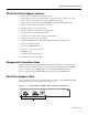
Catalyst RSM/VIP2 Ports Cisco 7505 Serial Port Number Example CP U ROUTE SWITCH PROCESSOR CO NS OL E HA LT PA-E3 (port numbers 3/1/0) SL SLO OT T 0 1 NO RM AL EJ EC T PA-E3 (port number 3/0/0) RE SE T Figure 8-3 F OO LL XM TR FE RF RL Slot 3 LL AIS OO F AIS RC VR RC D LE AB EN LK RF RL FE XM TR RC D VR LE AB RC EN LK E3 SERIAL E3 SERIAL Slot 2 Slot 1 Interface processor slots H10610 Slot 0 You can identify interface ports by physically checking the slot/port-adap
Identifying Port Adapter Slot and PA-E3 Interface Port Numbers Figure 8-4 Serial Port Adapters in the Catalyst 5509 WS-x5530 EM S ST U SY AT ST N VE FA 2 PS 1 100% ET TI ES AC T R WS-U5531-FETX 1 O SL 1 T PORT 1 LINK PCMCIA Load MDIX 10/100Mbps LINK AUX Switch 10/100 FAST ETHERCHANNEL EM S ST U SY AT ST 2 PORT 2 10/100Mbps SL CONSOLE MDIX 0 O PS SUPERVISOR ENGINE I I I WS-x5530 N FA 2 PS 1 PS VE 100% ET TI ES AC T R WS-U5531-FETX 1 O SL T PORT 1 CONSOL
Performing a Basic Configuration Slots in the Cisco 7140 series routers are numbered as shown Figure 8-6. The fixed LAN interface is slot 0, the fixed WAN interfaces are slots 1 and 2, and the modular port adapter interface is slot 4. Slot 3 is not used. Slot 5 is the service module.
Configuration Example Step 3 If IP routing is enabled on the system, change to interface configuration mode and use the ip address configuration subcommand to assign an IP address and subnet mask to the interface, as in the following example: router(config-if)# ip address 10.0.0.0 10.255.255.
Setting the Bandwidth Setting the Bandwidth In interface configuration mode, reduce effective bandwidth (range of 22 to 34010 kilobits per second) by entering the dsu bandwidth configuration subcommand, as in the following example: router(config-if)# dsu bandwidth 16000 Use the no form of this command to return to the default, 34010. Note The local port configuration must match the remote port configuration.
Configuring Cyclic Redundancy Checks Specifying E3 Framing In interface configuration mode, specify E3 framing by entering the framing {g751 | bypass} configuration subcommand, as in the following example: router(config-if)# framing g751 Use the no form of this command to return to the default, which is G.751 framing. Note If you use the bypass option, scrambling must be set to the default, disabled; the DSU mode must be set to the default, 0; and the DSU bandwidth must be set to the default, 34010.
Checking the Configuration For a VIP2, use the following example: router# configure terminal Enter configuration commands, one per line. router(config)# router(config)# interface serial 1/0/0 router(config-if)# crc 32 Ctrl-z End with CNTL/Z. For a Catalyst RSM/VIP2, use the following example: router# configure terminal Enter configuration commands, one per line. router(config)# router(config)# interface serial 0/0 router(config-if)# crc 32 Ctrl-z End with CNTL/Z.
Checking the Configuration Step 4 Specify one of the new interfaces as follows: • show interfaces port adapter type slot/port on Cisco 7100 series, Cisco 7200 series, and Cisco uBR7200 series routers • • show interfaces type slot/port adapter/interface command on the VIP2 show interfaces port adapter/interface command on the Catalyst RSM/VIP2 Verify that the first line of the display specifies the interface with the correct slot number and that the interface and line protocol are in the correct state
Using show Commands to Display Interface and System Information The following example of the show interfaces type slot/port command shows all of the information specific to the serial E3 port (interface port 0) in port adapter slot 2: router# show interfaces serial 2/0 Serial2/0 is up, line protocol is up Hardware is M1T-E3 pa Internet address is 172.16.0.
Checking the Configuration Output queue 0/40, 0 drops; input queue 0/75, 0 drops 5 minute input rate 0 bits/sec, 0 packets/sec 5 minute output rate 0 bits/sec, 0 packets/sec 0 packets input, 0 bytes, 0 no buffer Received 0 broadcasts, 0 runts, 0 giants, 0 parity 0 input errors, 0 CRC, 0 frame, 0 overrun, 0 ignored, 0 abort 4084 packets output, 1298712 bytes, 0 underruns 0 output errors, 0 applique, 0 interface resets 0 output buffer failures, 0 output buffers swapped out 0 carrier transitions For Cisco 71
Using show Commands to Display Interface and System Information For a Catalyst RSM/VIP2, use the show controllers serial command, using arguments such as those that specify the port adapter and port numbers (port-adapter/port), to display information that is specific to the serial interface hardware.
Checking the Configuration Following is an example of the show version command used with a Cisco 7500 series system: router# show version Cisco Internetwork Operating System Software IOS (tm) GS Software, Version 11.1(16)CA Synced to mainline version: 11.1(10.5) Copyright (c) 1986-1997 by cisco Systems, Inc. Compiled Thu 22-May-97 14:32 Image text-base: 0x600108E0, data-base: 0x60A00000 ROM: System Bootstrap, Version 5.3.2(3.2) [kmac 3.2], MAINTENANCE INTERIM SOFTWARE ROM: GS Software, Version 11.
Using show Commands to Display Interface and System Information To determine which type of port adapter is installed on a VIP2 in your system, use the show diag slot command.
Checking the Configuration For a VIP2, use the show controllers cbus command to display all of the current interface processors and their interfaces.
Using the ping Command to Verify Network Connection For a Catalyst RSM/VIP2, use the show controllers cbus command to display all of the current interfaces.
Checking the Configuration each signal that is not returned before the specified timeout is displayed as a period (.). A series of exclamation points (!!!!!) indicates a good connection; a series of periods (.....) or the message [timed out] or [failed] indicates that the connection failed. Following is an example of a successful ping command to a remote server with the address 10.0.0.0: router# ping 10.0.0.0 Type escape sequence to abort. Sending 5, 100-byte ICMP Echoes to 1.1.1.
Using the loopback Command to Verify the Physical Interface • Set the interface into network payload loopback mode as follows: Router# configure terminal Enter configuration commands, one per line. End with CNTL/Z. router(config)# interface serial 10/0/0 router(config-if)# loopback network payload Network payload loopback loops just the payload data back toward the network at the E3 framer.
Checking the Configuration 8-22 PA-E3 Serial Port Adapter Installation and Configuration