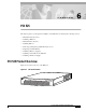
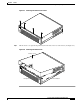
C H A P T E R 6 PIX 525 This chapter guides you through the installation of the PIX 525, and includes the following sections: • PIX 525 Product Overview • Installing a PIX 525 • PIX 525 Feature Licenses • Installing Failover • Removing and Replacing a PIX 525 Chassis Cover • Replacing a Lithium Battery • Installing a Memory Upgrade • Installing a Circuit Board in a PIX 525 • Installing a DC Power Supply PIX 525 Product Overview Figure 6-1 show the front view of the PIX 525.
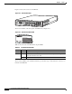
Chapter 6 PIX 525 PIX 525 Product Overview Figure 6-2 shows the rear view of the PIX 525. PIX 525 Rear Panel 61907 Figure 6-2 F A I L O V E R 100Mbps ACT LINK 10/100 ETHERNET 1 100Mbps ACT PIX-525 LINK 10/100 ETHERNET 0 USB CONSOLE There are two LEDs on the front panel of the PIX 525 (see Figure 6-3). PIX 525 Front Panel LEDs 61913 Figure 6-3 Table 6-1 lists the state of the PIX 525 front panel LEDs.
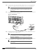
Chapter 6 PIX 525 Installing a PIX 525 Figure 6-4 shows the PIX 525 rear panel LEDs Figure 6-4 PIX 525 Rear Panel LEDs ACT(ivity) ACT(ivity) LED LED 100Mbps LINK LINK LED LED LED Failover connector F A I L O V E R LINK 10/100 ETHERNET 1 100Mbps ACT LINK 10/100 ETHERNET 0 PIX-525 USB 61912 100Mbps ACT CONSOLE 10/100 BaseTX USB Ethernet 1 port (RJ-45) 10/100 BaseTX Console Ethernet 0 port (RJ-45) (RJ-45) Table 6-2 lists the state of the PIX 525 rear panel LEDs.
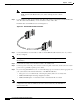
Chapter 6 PIX 525 Installing a PIX 525 Step 2 Connect the cable so that you have either a DB-9 or DB-25 connector on one end as required by the serial port for your computer, and the other end is the RJ-45 connector as shown in Figure 6-5. Note Step 3 Use the Console port to connect a computer to enter configuration commands. Locate the serial cable from the accessory kit. The serial cable assembly consists of a null modem cable with RJ-45 connectors, and one DB-9 connector and a DB-25 connector.
Chapter 6 PIX 525 PIX 525 Feature Licenses Step 6 Connect the network cables to the expansion interface ports. (The inside, outside, or perimeter network connections can be made to any available interface port on the PIX 525.) The first expansion port number, at the top left, is interface 2. Starting from that port and going from left to right and top to bottom, the next port is interface 3, the next is interface 4, and so on.
Chapter 6 PIX 525 Installing Failover Note Step 2 Both PIX Firewall units has to be the same model number, have at least as much RAM, have the same Flash memory size, and be running the same software version. Locate the failover cable (shown in Figure 6-6). This cable is shipped separately from the PIX Firewall unit. The cable is labeled Primary on one end and Secondary on the other. Install the cable for the PIX 525 as shown in Figure 6-6.
Chapter 6 PIX 525 Installing Failover Caution Do not turn the power on until the units are connected and the primary unit is configured completely.
Chapter 6 PIX 525 Removing and Replacing a PIX 525 Chassis Cover Step 7 Power the primary unit on first, then power on the secondary unit. Within a few seconds, the active unit automatically downloads its configuration to the standby unit. If the primary unit fails, the secondary unit automatically becomes active. Removing and Replacing a PIX 525 Chassis Cover This section describes how to remove and replace the chassis cover from PIX 525.
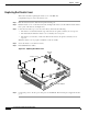
Chapter 6 PIX 525 Removing and Replacing a PIX 525 Chassis Cover Figure 6-7 Removing the Chassis Cover Screws PO WER TIVE 55324 AC CIS CO SEC U F I RITY R PIX E W 52 A L L 5 SERI ES Step 4 Lift the chassis cover upward and pull it away from the tabs on the rear of the chassis. (See Figure 6-8.
Chapter 6 PIX 525 Removing and Replacing a PIX 525 Chassis Cover Replacing the Chassis Cover This section describes replacing the chassis cover on the PIX 525. Complete these steps to remove the chassis cover: Step 1 Place the chassis bottom so that the front panel is facing you. Step 2 Hold the chassis cover over the chassis bottom, and align each of the cover tabs with the chassis tabs at the top rear of the chassis. (See Figure 6-9.
Chapter 6 PIX 525 Replacing a Lithium Battery Replacing a Lithium Battery The PIX Firewall has a lithium battery on its main circuit board. This battery has an operating life of about 10 years. When the battery loses its charge, the PIX Firewall cannot function. Contact Cisco TAC to replace the battery. Note Warning Do not attempt to replace this battery yourself. Danger of explosion exists if the lithium battery is incorrectly replaced.
Chapter 6 PIX 525 Installing a Memory Upgrade Step 2 Unpack the items in the memory upgrade kit. Remove the component tray and all the screws holding the assembly in place. Refer to “Removing and Replacing a PIX 525 Chassis Cover” for information on how to remove and replace the top panel. Determine the location of your system memory sockets (see Figure 6-10). Step 3 Use the markings on the motherboard to determine the socket numbers.
Chapter 6 PIX 525 Installing a Circuit Board in a PIX 525 Figure 6-11 Inserting a DIMM Memory Strip in a PIX 525 B B an an k 2 B k an 1 k 0 17997 DIMM B B an an k 2 B k an 1 k 0 17998 Figure 6-12 Securing a DIMM Memory Strip in a PIX 525 When you finish inserting new RAM memory, reinstall the tray on the PIX 525. Reattach the screws. If desired, rack mount the PIX Firewall and attach all cables and cords as discussed in previous sections.
Chapter 6 PIX 525 Installing a Circuit Board in a PIX 525 Note The PIX 525 Restricted Interface Options can have a maximum of 6 interfaces, and for the Unrestricted Interface Options, a maximum of 8 interfaces. Table 6-3 lists the possible choices available for the PIX 525 restricted and unrestricted interface options.
Chapter 6 PIX 525 Installing a Circuit Board in a PIX 525 Step 5 Attach the screw to hold the circuit board’s connecting flange to the rear cover plate on the component tray. 61911 Figure 6-14 Inserting an Expansion Board into a PCI Slot on the PIX 525 Component Tray Step 6 Figure 6-15 shows circuit boards in PCI slots on the component tray. 61909 Figure 6-15 Expansion Boards in PCI Slots on the PIX 525 Component Tray Step 7 Reinstall the component tray into the PIX 525 chassis.
Chapter 6 PIX 525 Installing a Circuit Board in a PIX 525 An illustration of the VPN Accelerator is shown in Figure 6-16. 61921 Figure 6-16 PIX Firewall VPN Accelerator Circuit Board Gigabit Ethernet Circuit Board PIX Firewall supports 1000 Mbps (Gigabit) Ethernet.
Chapter 6 PIX 525 Installing a DC Power Supply The Gigabit Ethernet circuit board and the fiber optic cable connection are shown in Figure 6-17.
Chapter 6 PIX 525 Installing a DC Power Supply Figure 6-18 Inserting the Power Supply in the Chassis Power supply 55329 Chassis hook Power supply slot Chassis bottom Step 3 Connect the six-pin connector to the motherboard. Step 4 Route the fan cables on top of fans exactly as shown in Figure 6-19. Note that the two longest cables are connected to the two installed fans on the right. The connectors to these two fans will fit into the space between the second and third fans.
Chapter 6 PIX 525 Installing a DC Power Supply 31109 Figure 6-19 Routing the Fan Cables Sheet metal tabs Base tabs Front panel Step 6 Insert the second fan as shown in Figure 6-19, making sure that the fan cable feeds to your left. Position the cables to the two installed fans so that they will fit over the first and second fans. Press the fan into place between the four sheet metal tabs. Step 7 Reconnect the two-pin fan cables to the remaining fan, as shown in Figure 6-20.
Chapter 6 PIX 525 Installing a DC Power Supply Figure 6-20 Reconnecting the Fan Cables Fan Fan connector 31910 Front panel Step 8 Reinstall the remaining fan. Make sure you orient the fan so that the cables feed to the right (toward the second fan). Route the cable over the fan before you reconnect it. When correctly assembled, the cables appear as shown in Figure 6-21.
Chapter 6 PIX 525 Installing a DC Power Supply 31109 Figure 6-21 Correct Fan Cable Routing Sheet metal tabs Base tabs Front panel Step 10 Replace the air separator as shown in Figure 6-22, holding all cables to the right of the separator as you slip it into the chassis.
Chapter 6 PIX 525 Installing a DC Power Supply Step 11 Replace the chassis cover as described in “Replacing the Chassis Cover.” Rerouting the Fan Wiring If the fan wiring in your router is not routed on top of the fans, you need to reroute the fan wiring. This will make future power supply replacement easier. Complete these steps to reroute the fan wiring: Step 1 Pull the fan closest to the power supply away from the sheet metal tabs. (See Figure 6-23.
Chapter 6 PIX 525 Installing a DC Power Supply Step 2 Lift the fan out of the chassis as shown in Figure 6-24. Figure 6-24 Removing the Fan 55327 Fan Chassis bottom Step 3 Caution Step 4 Depress the tab as shown in Figure 6-25. Do not attempt to remove the fan cables without first depressing the tab as shown in Figure 6-25. You can damage the fan cables by applying stress if the connector is not removed properly. Disconnect the fan cable as shown in Figure 6-25, and set the fan aside.
Chapter 6 PIX 525 Installing a DC Power Supply Figure 6-25 Disconnecting the Fan Cable Depress tab and pull outward Fan Fan connector 31106 Power supply Location of the three remaining fan connectors Step 5 Remove the next fan and disconnect its cable. Step 6 Remove the cables for the two remaining fans. Remove the last two fans. Step 7 Replace the fans, starting with the fan farthest away from the power supply.
Chapter 6 PIX 525 Installing a DC Power Supply Figure 6-26 Inserting Cable Clamp to the Fan Wiring clamp 31335 Front panel Step 9 Reconnect the two-pin fan cables to the remaining fan, as shown in Figure 6-26. Fan wiring colors are listed in Table 6-4. Step 10 Route the fan wire on the top surface of the fans. Place the fan wires straight, and do not twist the wires together. Locate the connectors in the gap between fans. (See Figure 6-21.
Chapter 6 PIX 525 Installing a DC Power Supply Figure 6-27 Attaching a Grounding Lug to the PIX Firewall Rear of PIX Firewall 11827 – + To rack ground 10-32 nuts Grounding studs on PIX Firewall DC model 2-hole copper standard barrel grounding lug Step 15 Ensure that power is removed from the DC circuit.
Chapter 6 PIX 525 Installing a DC Power Supply Step 18 Reconnect power to the PIX 525. After wiring the DC power supply, remove the tape from the circuit breaker switch handle and reinstate power by moving the handle of the circuit breaker to the ON position. Step 19 Insert the PIX 525 system diskette in the drive at the front of the unit. Step 20 Power on the unit from the switch at the rear of the unit.
Chapter 6 PIX 525 Installing a DC Power Supply Cisco PIX Firewall Hardware Installation Guide 6-28 78-13880-01