
Datasheet


6-4
Cisco PIX Firewall Hardware Installation Guide
78-13880-01
Chapter 6 PIX 525
Installing a PIX 525
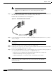
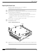
Step 2 Connect the cable so that you have either a DB-9 or DB-25 connector on one end as required by the
serial port for your computer, and the other end is the RJ-45 connector as shown in Figure 6-5.
Note Use the Console port to connect a computer to enter configuration commands.
Locate the serial cable from the accessory kit. The serial cable assembly consists
of a null modem cable with RJ-45 connectors, and one DB-9 connector and a
DB-25 connector.
Step 3 Connect the RJ-45 serial cable connector to the PIX 525 console connector and connect the other end
to the serial port connector on your computer.
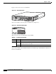
Figure 6-5 PIX 525 Rear Panel
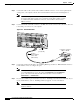
Step 4 Connect the outside network cable to the remaining Ethernet port. Refer to “PIX 525 Feature Licenses”
for information on how to configure the ports.
Note The inside or outside network connections can be made to any available interface
port on the PIX 525. If you are only using the ETHERNET 0 and ETHERNET 1
ports, connect the inside network cable to the interface connector marked
ETHERNET 0 or ETHERNET 1.
Step 5 If you need to install an optional circuit board, refer to “Installing a Circuit Board in a PIX 525”. If you
need to install memory, refer to “Installing a Memory Upgrade” for more information.
Note It is not necessary to remove the chassis cover of the PIX 525 to access the circuit
boards or memory.
F
A
I
L
O
V
E
R
100Mbps ACT
100Mbps ACT
LINK
LINK
PIX-525
10/100 ETHERNET 1
10/100 ETHERNET 0
USB
CONSOLE
61914
Console
port (RJ-45)
RJ-45 to
DB-9 or DB-25
serial cable
(null-modem)
Computer serial port
DB-9 or DB-25