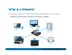
A network is a group of connected devices that enables users to share resources such as data, printers, and servers, tablets… laptop TV server printer PC © 2011 Cisco and/or its affiliates. All rights reserved.
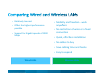
• Relatively low cost • Offers the highest performance possible • Mobility and freedom ‐ work anywhere h • No restriction of wires or a fixed • Support for Gigabit speeds of 1000 Mbps connection • Quick, effortless installation • No cables to buy • Save cabling time and hassle • Easy to expand Wired LANs © 2011 Cisco and/or its affiliates. All rights reserved.
Connect Your PCs, Servers and Tech Toys • Share high‐speed Internet connections No more waiting in line to get online • Share files No more carrying disks from office to office • Share printers Save money and time by sharing printers, scanners, and other peripherals • Share network storage • Security Protect your network resources from intruders or hackers Connect Wirelessly to enjoy the freedom to work from anywhere! © 2011 Cisco and/or its affiliates. All rights reserved.
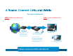
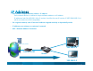
Two Types of Networks LAN (Local Area Network) WAN (Wide Area Network) Modem A modem links your home network to the Internet through your Internet Service Provider (ISP). Router PC with IP1 (here, a Linksys EA6300) A router is a device that forwards data from one network to another. It identifies how to send the packages to the right devices by giving an address (IP) to every single devices. Laptop with IP2 A Router connects a LAN to the Internet © 2011 Cisco and/or its affiliates.
• Each PC has a unique hardware address – MAC address Each network device or card has a unique hardware address – MAC address (Layer 2) A MAC address looks like 98:FC:11:84:B1:60 • On a typical network, each PC has a MAC address assigned during manufacturing • Every MAC address is unique • The MAC address is written on a label on the device. © 2011 Cisco and/or its affiliates. All rights reserved.
• Each PC has a unique software address – IP address Each network device or card has a unique software address: an IP address. IP addresses look like 192.168.1.4 for IP version 4 and for the new IP version 6: 2607:f0d0:1002:51::4 (all of our routers are IPV6 compatible) • On a typical network, each PC has an IP address assigned statically or dynamically onsite • IP addresses are unique on a customer’s network • NAT – Network Address Translation Internet provider 192.168.1.3 183.45.3.
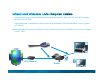
• Previous to AC, wired network offered the fastest speeds possible. Now, with AC, your Wi/Fi network can run up to 1.3 Gbps. • High‐speed cable is available for transfer rates up to 1000 Mbps (10/100/1000 Mbps = up to 1 gigabit per second) Networking cables are known by different names: Ethernet cable, RJ‐45 (telephone wire is RJ‐11), Category 5, CAT5, CAT6 ADSL Modem Router © 2011 Cisco and/or its affiliates. All rights reserved.
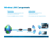
• Wireless Router • Wireless Adapter • Enables wireless‐equipped computers and other devices to communicate • Enables laptop and desktop PCs to communicate wirelessly • Connects via wired connection to Modem • All new laptops now have integrated wireless PC with wireless adapter ADSL Modem Router ((here a Linksys y E900)) © 2011 Cisco and/or its affiliates. All rights reserved.
• The air is getting more and more crowded d d • Lots of interferences • 2.4 2 4 GHz • 5 GHz • Customers need a Dual Band solution! © 2011 Cisco and/or its affiliates. All rights reserved.
• Avoid the 2.4GHz jam now, take the 5 GHz Highway! © 2011 Cisco and/or its affiliates. All rights reserved.
© 2011 Cisco and/or its affiliates. All rights reserved.
•Less crowded 5GHz Band up to 20 non‐interfering channels 2.4GHz Band only 3 non‐interfering channels © 2011 Cisco and/or its affiliates. All rights reserved. •More channels in the band to avoid neighboring network interference Higher Priority •Separated from 2.
WIRELESS STD FREQUENCY SPEED INTEROPERABILIT Y 802.11 2.4 GHZ 2 MBPS 802.11b 2.4 GHZ 11 MBPS 802.11a 80 a 5.0 5 0G GHZ 54 MBPS 5 S 802.11g 2.4 GHZ 54 MBPS 802.11b 802.11n 2.4 GHZ/5GHZ DUAL BAND 450 MPBS 802.11a/b/g 802.11AC 5GHZ 1.3 GBPS 802.11 a/b/n 802.11, 802.11g • Pros of 2.4 2 4 GHz - lowest cost; signal range is good and not easily obstructed • Cons of 2.
Wireless Standard Solution Type Wireless‐G Wireless‐N Wireless‐AC Outdated Lowest price Best Performance Data rate up to 54Mbps Up to 450 Mbps on 2.4 Ghz band and up to 450 Mbps on the 5Ghz band Up to 3x faster than Wireless N on the 5Ghz band (1300Mbps) Super Cheap Cheap Best value 2.4 GHz Band 2.4 & 5GHz Band 5Ghz band (most of the routers carry the 2.4Ghz band as well Typically up to 100‐150 f t iindoors.
Why AC matters Wireless Performance Comparison 1,300 Spe eed in Mb/s Offers more bandwidth and is less impacted by interference 867 AC 433 N 0 1x1 Allows you to do more at the same time, creating a better entertainment experience Extends the battery life of mobile devices by achieving the same transfer speed more efficiently AC products are compatible with all existing wireless clients 2x2 3x3 Antenna configuration © 2011 Cisco and/or its affiliates. All rights reserved.
© 2011 Cisco and/or its affiliates. All rights reserved.
Ideal for: Wireless‐G Wireless‐N Wireless‐AC Sharing a high speed Internet connection Public hotspot compatibility Transmitting audio files Internet phone calls (VoIP) Multiple users with heavy Internet usage or file sharing Large homes and offices Networked entertainment; streaming HD video, high definition video, multi‐channel surround sound audio Multiple simultaneous applications including VoIP, audio, video Lag‐free multi‐player gaming over the wireless net
• RE2000 – WIRELESS N DUAL BAND RANGE EXTENDER + BRDIGE • WAP300N – WIRELESS N DUAL BAND ACCESS POINT ( 4 IN 1) • PLWK400 – WIRLESS N DUAL BAND POWERLINE • EA6500 – WIRELESS AC DUAL BAND GIGABIT ROUTER WITH 2 USB © 2011 Cisco and/or its affiliates. All rights reserved.
• Support.linksys.com/productname • Support.linksys.com/re2000 Support linksys com/re2000 • Support.linksys.com/wap300n • ARABIC/ENGLISH TECHNICAL SUPPORT NO 800 844 5905 © 2011 Cisco and/or its affiliates. All rights reserved.
• VIDEO © 2011 Cisco and/or its affiliates. All rights reserved.
RE2000 Selectable Dual-Band Wireless-N Range Expander ZAFER MOHIUDDIN
Product Introduction • Hardware Requirements and Product Comparison) Hardware, LED General Hardware Summary Device Installation (Setup Software) Support pp Reminders
• Usage scenario – Add wired devices to wireless network. Wired PC’s Wireless PC @ 2.4 GHz Wireless PC @ 5 GH GHz Linksys switch Media Server HD Ethernet connection USB connection Wireless connection @ 2.4 2 4 GHz Wireless connection @ 5 GHz © 2011 Cisco and/or its affiliates. All rights reserved. Range Extender RE 1000 2.
• It can operate in either 2.4 GHz or 5.0 GHz radio bands (selectable dual-band) • 802.
Windows Mac OS X Windows XP SP3 Leopard 10.5.8 or later Vista SP1 Snow Leopard 10.6.1 or later Windows 7 Lion 10.7 or later Windows 8 Mountain Lion 10.
Dual Band RE1000 RE2000 No (802.11 b/g/n) Yes (802.11 a/b/g/n) Data Rate Up p to 300Mbps p Up p to 300Mbps p (2.4GHz & 5GHz) WPS Yes Yes Built in DHCP Survey Built-in Yes Yes Default IP 192.168.1.1 192.168.1.
RE1000 Cisco Logo is an LED RE1000 v1.5 Single LED above the Cisco logo RE2000 RE2000 LED is now a green bar.
LED One multi-purpose LED (green, bar shape) on the top of the device.
Physical Button Power Supply One push O hb button tt for f Wi-Fi Wi Fi Protected Setup. One reset button for resetting the device to g One p power p push factoryy settings. button (for European model only). Built-in B ilt i power supply l with ith worldwide voltage support (100240V). Supports interchangeable power p p plug g clip-on p and p pig-tail g power cable. The type (US, EU, AU, UK) of clip-on(s) and cable(s) being shipped depends on the target country of the SKU SKU.
• The setup software is used to connect the RE2000 to an existing wireless network, allowing you to connect to a 2.4GHz or 5GHz network. • It will not install any software on the local computer.
• The Setup software can only run on a wireless computer (wireless adapter must be enabled) in order to scan for wireless networks. Same as the RE1000. • If setup must be configured from a wired computer, simply access the UI to manually configure the extender.
• In a scenario where there is a dual band router or multiple SSID’s with the same name but different bands, the setup software will display one SSID but will display 2.
• When you select the SSID, you will be given the option to select to which b d you want the band h extender d to connect to.
• Same as RE1000 but the Site Survey page will now display 5GHz band networks.
Linksys Wireless Wireless-N N Range Extender N300 Dual Band • RE200 Unconfigured- Pressing the WPS looks for a wireless router/AP to connect to (with WPS being activated on the router or AP) • RE2000 Configured- Pressing the WPS acts as a registrar and scans for WPS clients.
Linksys Wireless Wireless-N N Range Extender N300 Dual Band • Default username blank/ default password is admin • MAC address on label is for Ethernet port • The default IP is 192.168.1.1 192 168 1 1 when it hasn’t hasn t detected a DHCP server on the network. It gives out a short lease of 192.168.1.x IP address.. • Default SSID is “LinksysExtenderXXXXX” where XXXXX is the last 5 digits of the serial number of the device.
• When possible remember to use the Setup Utility and make sure the range expander is close to the router when first setting it up. • If you cannot use the setup CD a WPS configuration will be a good fast alternative. • Always remember to verify signal strengths within the UI after placing the devices in their fi l llocations. final ti • This device should be supported for all theatres. © 2011 Cisco and/or its affiliates. All rights reserved.
WAP300N Linksys Wireless-N Access Point N300 Dual-Band Mi h l Flis Michal Fli January 2013
• New Product ID • Product P d O Overview i • Ports, Buttons and LED behavior • Setup Software • Device Modes • Setup over the GUI • Summary
• The WAP300N comes with two external antennas and its dual-band selectable (2.
• 4 Modes: Access Point, Wireless Media Connector, Wireless Range Extender, Wireless Bridge • Built-in DHCP Server • 2x2 MIMO • 2 External removable antennas • Compliant with 802.
WAP300N WAP610N WAP54G 802.11a/b/g/n 802.11a/b/g/n 802.11g 2.4 or 5 2T2R Yes 2.4 or 5 2T3R Yes 2.4 N/A Yes Wireless Media Connector Function (a.k.a. AP Client Function) Yes No Yes 2 Wireless Range Extender Function (a.k.a.
Port Count Description Ethernet 1 10/100 RJ45 LAN port with auto-MDIX Power 1 Power port for connecting power adapter.
Button Reset (Underneath) Power Switch (EU model only) Wi-Fi Protected p Setup Count 1 1 1 Description Reset button. Press and hold about 5 seconds to reset settings to factory default. Rocker switch switch. Power switch for turning on and off the device. Wi-Fi Protected Setup push button.
• Reset button. Press .
• Is used to configure the wireless settings in Access Point mode only • To configure using other modes you need to access the WAP’s UI • Will not install any software on the computer • Will give you an option to select which band to configure
AP Mode Requirement Access Point Mode Existing Network Wireless Media Connector Mode Existing a/b/g/n wireless router or AP and Active Ethernet Port Wireless Range Extender Mode Existing a/b/g/n wireless router or AP g Mode Wireless Bridge Additional WAP300N
• Upgrades pg a wired router to a wireless network • Upgrades an older wireless network to 802.
• When you change the WAP into this mode, the Wireless tab will change similar to other Media Connectors. You will have the Site Survey option as well. • You can also plug the WAP in this mode into a switch and all wired devices behind the switch will obtain an IP up to 64 wired clients (in theory; not fully tested.
• Extends the wireless range of an existing wireless network (does not need to be p plugged gg into the router)) • Adds wireless networking capability to any wired (Ethernet) device. • Can only extend one band at a time. • If connecting a switch a total of 64 clients are supported (wired+wireless) (wired wireless) (in theory; not fully tested.
• Based on WDS (Wireless Distribution System) System). No standardization for WDS, WDS may vary from vendor to vendor therefore in this mode it must be used with another WAP300N. • Requires 2 or more WAP300N to operate. operate One WAP in Bridge mode must be wired to existing router/network. This way all other WAP’s in bridge mode can communicate back to router/network. The existing network does not need to have an existing Wi-Fi network.
Do not create a loop in your network.
The use of WPS will depend on the mode the WAP300N is currently configured as: • Access Point mode- Wireless clients to WAP300N • Wireless Media Connector mode- WAP300N to a wireless router or Access point • Wireless Wi l R Range E Extender t d moded WAP300N to t a wireless i l router, t A Access point i t or wireless clients • Wireless Bridge mode- No WPS support (configuration is based on Local Mac address dd and d nott wireless i l settings) tti )
• Computer physically connected to the access point via Ethernet can easily communicate with the device and carry out the setup process even before the access point is connected to the primary DHCP server of the home network. • Enabled when the access point has detected that there is no other DHCP server on the network. Otherwise, the built-in DHCP server is disabled and the device behaves as a DHCP client. • When the built-in DHCP server is enabled - IP address of WAP300N is 10.100.1.
Default IP Address 10.100.1.
• If the WAP is connected to the existing network and the UI needs to be accessed, the customer will need to determine the IP by either looking up the oute s DHCP C tab ea d/o us ga y ot e method et od to dete e it’s t s IP. router’s table and/or using any other determine • Faster way for support to configure it may be by connecting directly to computer, configure it and then placing it back on the network.
• The Setup > Network Setup page • We can configure the WAP300N to have a Static IP address once we accessed the Setup Page
• The Setup > Operation Mode page • This is where you can go to change the Operation mode of the WAP300N. WAP300N Default is Access Point.
• The Wireless Settings page of the WAP300N on “Access Point” mode • Configuration, look and feel is similar to a Linksys dual band router.
• SSID broadcast can be enabled/disabled in Access Point mode
• The Wireless Settings page of the WAP300N on “Wireless Media Connector” and “Wireless Range Extender” mode. • You can connect to the Y h upstream wireless i l router/AP /AP manually ll b by using i this hi page or use the Wireless Network Site Survey tab.
• When WAP300N is in Wireless Range Extender mode, once WAP300N is connected to the upstream wireless router/access point, WAP300N’s SSID would change to match with that of the upstream router/access point. point • In case connection to the upstream router/access point fails, WAP300N’s SSID would fall back to its default SSID (“CiscoXXXXX”).
• The Wireless Network Site Survey tab will display a list of access points detected . • Select the preferred AP on the list and enter the wireless network password password.
• The Wireless S tti Settings page off the WAP300N on “Wireless Bridge” mode.
Local WiFi MAC address that will be entered on the opposite WAP • Use the wireless MAC address found in the Wireless>Basic Wireless Settings page • Select a band (bands must be the same for each WAP ex: Y can nott You select 5GHz on one WAP300N and 2.4GHz 2 4GHz on another WAP300 in bridge mode).
• All wireless settings must be the same on all Bridge mode WAPs
Note: Mac address printed on label is for the Ethernet port and NOT to be used for Bridge configuration
Operation Mode ode Access Point Wireless Media Connector Wireless Range Extender Wireless Bridge Basic Wireless Settings X Wireless Security Secu ty Wireless Network Site Survey X X X X X X Wireless MAC Filter X QoS X X X • The sub-pages available under the page Wireless depend on the operation mode that WAP300N is in
• Installation, Configuration and Setup are fully supported based on the requirements. Note that OS requirement is solely for the Setup software. • Absolutely no support will be provided if 3rd party antennas are b i used being d ((voids id warranty) t ) • Whole unit replacement or replacements of antennas are available within warranty if the antennas are missing, or damaged. • There will be a $15 charge for replacement of antennas through customer t service i when h outt off warranty.
Linksys PLW400: Powerline AV Wireless Network Extender
• Product Overview • WPS Setup • Product Utility • User Interface • Known Issues/Recommendations © 2011 Cisco and/or its affiliates. All rights reserved.
P d t Overview Product O i © 2011 Cisco and/or its affiliates. All rights reserved.
PLW400 PLE400 • PLW400- Powerline 1-Port Fast Ethernet Network Adapter & AP • PLWK400 - Powerline Wireless Kit Includes 1 PLE400 + 1 PLW400 © 2011 Cisco and/or its affiliates. All rights reserved.
High speed (up to 200 Mbps) for faster transfer rates Fast Ethernet port (1 x 10/100) to connect to any wired device Wireless flexibility (802.11n/2.4GHz) for additional wireless connections in the home 2x2 MIMO and WLAN data rate of up to 300Mbps Push button security- Wi-Fi Protected Setup for simple and secure device paring © 2011 Cisco and/or its affiliates. All rights reserved.
• By y simply p y adding g the PLW400 adapter p to an existing g Powerline network (wireless), a new wired and wireless network connection is established © 2011 Cisco and/or its affiliates. All rights reserved.
Wired Router • By y simply p y adding g the PLW400 adapter p to an existing g Powerline network (wired), a new wired and wireless network connection is established © 2011 Cisco and/or its affiliates. All rights reserved.
Video © 2011 Cisco and/or its affiliates. All rights reserved.
• PC or other device with Ethernet network port • AC Power Outlet • At least 1 existing in home Powerline adapter • PC/Mac with CD-ROM for utility or WPS enabled router © 2011 Cisco and/or its affiliates. All rights reserved.
WPS Button LED Indicator PLC Reset RJ45 Port © 2011 Cisco and/or its affiliates. All rights reserved.
LED STATUS DESCRIPTION Power Off Device off Flashing g Indefinitely Pairing g error or system y error Flashing Fast Factory default Solid Device ready Off Not connected to Ethernet network Flashing Send/receive data S lid Solid C Connected t d tto Ethernet Eth t network t k Ethernet © 2011 Cisco and/or its affiliates. All rights reserved.
LED STATUS DESCRIPTION HomePlug Off Not connected to HomePlug network Flashing g Fast Send/receive data Flashing Slow Pairing Solid Connected to HomePlug network Off WLAN is disabled or failed to work Flashing Send/receive data S lid Solid WLAN is i enabled bl d and d ready d tto work k WLAN © 2011 Cisco and/or its affiliates. All rights reserved.
LED STATUS WPS Fl hi slow Flashing l WPS in i progress. U Up tto 2 minutes i t © 2011 Cisco and/or its affiliates. All rights reserved. DESCRIPTION Flashing fast WPS error or session overlap.
WPS Setup S t © 2011 Cisco and/or its affiliates. All rights reserved.
1. Plug the PLW400 to a power outlet and press the WPS button located on the side side. © 2011 Cisco and/or its affiliates. All rights reserved.
2. Press the WPS button on the router to quickly get the wireless network t k settings. tti 3. WPS will be synched. You can now move the PLW400 to the desired location in the home. © 2011 Cisco and/or its affiliates. All rights reserved.
• Even though g the SSID of the main network will be the same as the SSID of the PLW400, the data will still flow through the walls. © 2011 Cisco and/or its affiliates. All rights reserved.
P d t Utility Product Utilit © 2011 Cisco and/or its affiliates. All rights reserved.
1. Connect your PLW400 to a power outlet. 2. Use an Ethernet cable to connect the PLW400 to your computer (it is recommended to run the utility from a wired computer if possible). possible) 3. Install the Cisco Powerline AV Utility software. © 2011 Cisco and/or its affiliates. All rights reserved.
Network Status • Displays a device list with device name, model, MAC address, device password, p , firmware version and PLC physical layer line rate © 2011 Cisco and/or its affiliates. All rights reserved.
Security • Displays device list • Displays default encryption key HomePlug AV • Allows user to change network password/encryption keyy (8~64 ( ASCII characters) © 2011 Cisco and/or its affiliates. All rights reserved.
QoS • Allows user to configure the device and protocol priority • Allows user to configure QoS setting by 802.1Q VLAN tag or TOS field in the IP header © 2011 Cisco and/or its affiliates. All rights reserved.
Ad i i t t Administrator • Displays utility version • Language Selection • Allows user to restart l local l adapter d t • Allows user to restore local device to factory default © 2011 Cisco and/or its affiliates. All rights reserved.
Wi l Wireless • Display SSID and wireless security mode and passphrase • Allow user to assign g the PLW400 its own SSID, wireless security mode and passphrase h • URL link to login the PLW400 Web GUI © 2011 Cisco and/or its affiliates. All rights reserved.
• After configuring the necessary settings on the product utility, moved it to the desired location in the home, and connect the laptop wirelessly. • The screenshot above shows the PLW400 under the DHCP client table of the router. © 2011 Cisco and/or its affiliates. All rights reserved.
U User IInterface t f © 2011 Cisco and/or its affiliates. All rights reserved.
• Enter the IP address of the PLW400. PLW400 This can be found on the Wireless Setting page of the product utility. © 2011 Cisco and/or its affiliates. All rights reserved.
• Network address of the PLW400 can be defined on this page. © 2011 Cisco and/or its affiliates. All rights reserved.
• IPv6 Setup page © 2011 Cisco and/or its affiliates. All rights reserved.
• Wi-Fi Protected Setup pp page g © 2011 Cisco and/or its affiliates. All rights reserved.
• Basic settings for wireless networking g are set on this screen © 2011 Cisco and/or its affiliates. All rights reserved.
• Settings for wireless security are found on this section. © 2011 Cisco and/or its affiliates. All rights reserved.
• Wireless access can be filtered by using the MAC addresses of the wireless devices transmitting within your network’s range. © 2011 Cisco and/or its affiliates. All rights reserved.
• Administration > Management screen allows the network’s administrator to manage specific powerline adapter functions for access and security © 2011 Cisco and/or its affiliates. All rights reserved.
• Diagnostic tests (Ping and Traceroute) allow you to check the connections of your network devices, including connection to the Internet. © 2011 Cisco and/or its affiliates. All rights reserved.
• Administration > Factory Defaults screen allows you to restore the powerline adapter’s configuration to its factory default settings. © 2011 Cisco and/or its affiliates. All rights reserved.
• Firmware Upgrade screen allows you to upgrade the powerline p firmware. adapter’s © 2011 Cisco and/or its affiliates. All rights reserved.
• Displays information about the access point and its current settings. © 2011 Cisco and/or its affiliates. All rights reserved.
• Displays information about your wireless network.. © 2011 Cisco and/or its affiliates. All rights reserved.
Known Issues / Recommendations © 2011 Cisco and/or its affiliates. All rights reserved.
By default, there is no wireless security set on the PLW400. If a customer just plugs it into their network, people could have an open access. • User needs to setup a secure wireless network. © 2011 Cisco and/or its affiliates. All rights reserved.
Information on the Wireless Settings tab and Firmware Version on the Network Status tab are not available or not displayed properly when customer opens the Product Utility of the PLW400 using a wireless computer. • Access the UI of the PLW400 from a browser • You can plug in an Ethernet cable into the PLW400 device or router from the PC and run the utility © 2011 Cisco and/or its affiliates. All rights reserved.
An error “Cannot find IP” will be displayed when the customer clicks on the Wireless Settings tab of the Product Utility using a wireless computer • You can plug in an Ethernet cable into the PLW400 device. © 2011 Cisco and/or its affiliates. All rights reserved.
• The product utility for the PLW400 cannot manage older ld Powerline P li devices d i lik like the th PLE200/PLE300/PLTE200 units, which is due to them having a different chipset. © 2011 Cisco and/or its affiliates. All rights reserved.
Linksys EA-Series EA Series 6500 AC Router
• Introduction to 802.11ac • Near field communication (NFC) • Product Overview • Setup Experience • New Cisco Connect Cloud Features • Summary Comparison © 2011 Cisco and/or its affiliates. All rights reserved.
I t d ti to Introduction t 802.11ac 802 11 © 2011 Cisco and/or its affiliates. All rights reserved.
• The Th extraordinary t di growth th iin the number and type of WiFi devices, coupled with the increasing popularity of bandwidth intensive activities such as high definition video streaming, has created the demand for better performance with greater reach • 802.11ac,, the 5th generation Wi-Fi standard is designed to meet these needs. © 2011 Cisco and/or its affiliates. All rights reserved.
802.11ac – The 5th Generation Wi-Fi Wi Fi Standard • Supports the same use cases as 802.11n 802 11n which is Data Data, Video and Voice • With similar range (30-100 feet) • At Very High Throughput (VHT), the new 802.11ac standard can achieve a speed of up to 1 Gigabit+ per second © 2011 Cisco and/or its affiliates. All rights reserved.
802.11ac – The 5th Generation Wi-Fi Standard • Offers more bandwidth and is less impacted by interference • Allows you to do more at the same time, creating a better entertainment experience • Extends the battery life of mobile devices by achieving the same transfer speed more efficiently • AC products are compatible with all existing wireless clients © 2011 Cisco and/or its affiliates. All rights reserved.
C Core N New T Technologies h l i © 2011 Cisco and/or its affiliates. All rights reserved.
Data Bits per Subcarrier 256QAM@r5/6 64QAM@r5/6 40MHz 80MHz 160MHz Bandwidth 4 11n AP 11ac AP 8 #Spatial Streams © 2011 Cisco and/or its affiliates. All rights reserved.
802.11n: 20 and 40 MHz channels 802.11ac: 80, 160, 80+80 MHz channels • The wider the channel, the faster data can be transferred • i.e. a 40 MHz channel transfers 2X that of a 20 MHz channel and an 80 MHz channel transfers 4X that of a 20 MHz channel © 2011 Cisco and/or its affiliates. All rights reserved.
• The 802.11ac 802 11ac standard also takes advantage of advanced modulation techniques that allow the technology gy to cram more bits of data into every transmission. • This is comparable to use of carpools and buses for transporting more people over the same number of lanes in a highway. © 2011 Cisco and/or its affiliates. All rights reserved. 802. 11n 64 QAM 802.
802.11n offers 1-4 spatial streams • IEEE 802.11ac translates MIMO up to eight (8) spatial streams, versus the four of 802.11n. Thus, increased spatial streams should be delivered at a considerably higher throughput than current IEEE 802.11n provisions. i i © 2011 Cisco and/or its affiliates. All rights reserved.
C lN Cool New T Technologies h l i © 2011 Cisco and/or its affiliates. All rights reserved.
802.11n: SU-MIMO p Total Data Rate: 433 Mbps • In a normal MIMO environment, devices compete p for channel use in a non-cooperative manner. Early 802.11ac clients will be predominantly tablets and smart phones. The clients will have 1x1 802.11ac radios, limiting them to 433Mbps. In single user MIMO, the total data rate of the net ork will network ill be 433 Mbps Mbps. © 2011 Cisco and/or its affiliates. All rights reserved.
802.11ac: MU-MIMO Total Data Rate: 866 Mbps p p p g to direct spatial p • MU-MIMO uses spatial multiplexing streams in the same channel to different receivers, allowing for more efficient use of the channel. Two 1x1 802.11ac device will each have its own 433Mbps data rate spatial stream, bringing the total network data rate to 866Mbps © 2011 Cisco and/or its affiliates. All rights reserved.
• Beamforming provides directional signal transmission and reception. • Previous standards can only receive and transmit omnidirectional signals, which are subject to significant levels of j g interference, due to the fact that the signals are transmitted indiscriminately in every possible di ti direction. © 2011 Cisco and/or its affiliates. All rights reserved. 802.
• With beamforming, there’s an understanding of the relative location of the device, and the signal is correspondingly strengthened in that direction 802.11ac © 2011 Cisco and/or its affiliates. All rights reserved.
802.11n Dead Spots 802.11ac Total Coverage • Homes and apartments now plagued with "dead spots" will enjoy vastly improved reception. But 802.11ac networks, with beam-forming and other innovations, do a much better job in penetrating all forms of building materials, materials including concrete than its predecessors. predecessors © 2011 Cisco and/or its affiliates. All rights reserved.
© 2011 Cisco and/or its affiliates. All rights reserved.
video © 2011 Cisco and/or its affiliates. All rights reserved.
802.11n 802.11ac Throughput Up to 450 Mbps Up to 1 Gbps Channel Width 20 MHz and 40 MHz channels 80, 160, 80+80 MHz channels** channels Modulation 64 QAM 256 QAM Number of Spatial St Stream 1-4 1-8** Beamforming Mechanism No Yes RF Band 2.4 GHz or 5 GHz 5 GHz only © 2011 Cisco and/or its affiliates. All rights reserved.
N Near fifield ld communication i ti (NFC) © 2011 Cisco and/or its affiliates. All rights reserved.
Near field communication (NFC) • Near field communication (NFC) is a set of standards for smartphones and similar devices to establish radio communication with each other by y touching g them together or bringing them into close proximity, usually no more than a few centimeters. Present and d anticipated ti i t d applications li ti include contactless transactions, data exchange, and simplified setup of more complex communications such as WI-FI © 2011 Cisco and/or its affiliates. All rights reserved.
• NFC technology has the power to b i new bring simplicity and convenience to manyy aspects p of a typical person's daily life, as this example illustrates • NFC Forum http://www.nfcforum.org © 2011 Cisco and/or its affiliates. All rights reserved.
• Mb: megabits per second; MB: megabytes per second • Channel width: how much radio frequency is used by a channel; the wider the channel, the faster data can be transferred, i.e. a 40 MHz channel transfers 2x that of a 20 MHz channel and an 80 MHz channel 4x a 20 MHz channel. • PHY rate: speed of raw channel without the overhead of media access protocol, i.e. Gigabit Ethernet is 1000 Mb • Data rate: speed user data is transferred, i.e. Gigabit Ethernet is ~ 650 Mb.
• Spatial stream: unique simultaneous data stream • Each spatial stream has a PHY rate of 150 Mb: 1x1 = 150 Mb, 2x2 = 300 Mb, 3x3 = 450 Mb • Example: p “N900” has 3 spatial p streams ((3x3)) at 5 GHz and 3 spatial p streams (3x3) at 2.4 GHz. So, it has a 450 Mb PHY rate at 5 GHz and a 450 Mb PHY rate at 2.4 GHz for a total PHY rate of 900 Mb, thus the name “N900”.
P d t Overview Product O i © 2011 Cisco and/or its affiliates. All rights reserved.
Linksys EA6500 Linksys EA4500 Linksys EA3500 Linksys EA2700 © 2011 Cisco and/or its affiliates. All rights reserved.
Model EA2700 EA3500 EA4500 EA6500 Wireless speed Up to 300Mbps 300Mbps (2.4GHz) 450 Mbps (5GHz) Up to 450 Mbps + 450 Mbps 450Mbps (2.4GHz) 1.3Gbps (5GHz) Ethernet Ports x Speed 4 x 10/100/ 1000 4 x 10/100/ 1000 4 x 10/100/ 1000 4 x 10/100/ 1000 TX/RX 2 internal antennas each for 2 4GHz and 2.4GHz 5GHz 2TX x 3RX for 2.4Ghz 3TX x 3RX for 2.4Ghz 3TX x 3RX for 2.4Ghz 3TX x 3RX for 5Ghz 3TX x 3RX 5Ghz 3TX x 3RX 5Ghz Dual band ((2.4GHz and 5GHz) Dual band ((2.
Model EA2700 EA3500 EA4500 EA6500 Parental Controls (Basic) Supported pp Supported pp Supported pp Supported pp Guest Access Supported Supported Supported Supported Not available Available (capable of supporting one external t l HD or USB printer) Available (capable of supporting one external t l HD or USB printer) Available (Dual USB ports to connectt 2 hard h d drives or 2 printers or one of each.)) USB port NFC Not Supported © 2011 Cisco and/or its affiliates. All rights reserved.
EA6500 Draft 802.11ac (Compatible with a/b/g/n) Local Access UI (Option to Opt Out of cloud services, no cloud account required) Cisco Connect Cloud services support 2 USB 2.0 port (Simultaneous): Printing (Virtual USB) Storage Link (FAT, FAT32, NTFS, HFS+ journaled & non-journaled) SimpleTap Technology (NFC) Cisco Connect Cloud mobile app with SimpleTap Simultaneous Dual Band: MIMO 3x3 (2.4Ghz) and MIMO 3x3 (5Ghz) Data rates up to 450 Mbps on 2.
EA6500 Two single-color LEDs (Green) & (Yellow) LED COLOR ACTIVITY DESCRIPTION Two single-color LEDs corresponding to each Ethernet port to indicate link status Green Off No physical link on the LAN port Solid (green) Physical link is up Flashing (yellow) Data is transmitting through this port © 2011 Cisco and/or its affiliates. All rights reserved.
EA6500 LED COLOR ACTIVITY DESCRIPTION Power (Cisco logo) White Off Power off Solid Power on / Device is ready / WPS is successful Blinking Reboot due to failed FW upgrade / WPS PBC session overlap or error (up to 120 seconds) d ) Booting / System self-test / Firmware upgrade WPS in progress (up to 120 seconds) Pulsing (fast) Pulsing (slow) © 2011 Cisco and/or its affiliates. All rights reserved.
4 Gigabit LAN Ethernet switch ports 1 Gigabit WAN port Reset button rocker-style power switch 12V/3A DC power jack Wi-Fi Protected Setup (WPS) Port 2 USB 2.0 ports EA6500 DESCRIPTION Ethernet 4 10/100/1000 RJ45 LAN port with auto-MDIX I t Internet t 1 10/100/1000 RJ45 Internet I t t portt with ith autot MDIX USB 2 USB Port Wi-Fi Protected Setup (blue) 1 Wi-Fi Protected Setup push button. Reset 1 Reset button.
S t Experience Setup E i © 2011 Cisco and/or its affiliates. All rights reserved.
• Firmware shipping with router • Does not support dual USB storage • Does not support cloud services • Limited widgets only (Offline and Online) • Setup CD will update firmware to load all features. • Manual setup will prompt customer to download and update firmware. Once firmware is updated it will include support for all items mentioned above. • So long as router has internet connection during setup software, it will detect the upgrade and install itit, it’s it s part of the installation.
Online (Setup software successfully detects Internet connection) 1 1. Software sets up the Internet connection 2. Setup wireless network 3. Detects update and downloads it. 4 4. O ti to Option t create t CCC account. t Offline 1. Software detects no WAN connectivityy and prompts p p to check WAN connection and goes through troubleshooting. If router gets online steps 2-4 above are completed, otherwise Setup prompts customer to contact Support. © 2011 Cisco and/or its affiliates.
Online 1 1. Opening UI by entering “myrouter myrouter.local local” in the address bar of browser 2. Access Router admin password prompt 3. Prompt for required update (Prompt will come up once router has been manually configured for Internet connection, otherwise the user will not see the prompt) © 2011 Cisco and/or its affiliates. All rights reserved.
Online a. Skip - returns user to limited UI with an orange banner on the top b. Update Now - updates firmware on the router with added support for cloud services and dual USB support. © 2011 Cisco and/or its affiliates. All rights reserved.
Offline 1 1. Opening UI by entering “myrouter myrouter.local local” in the address bar of browser 2. Prompts for router admin password “Access Router” 3. Access to limited UI (No Update firmware messaging since router is not online) © 2011 Cisco and/or its affiliates. All rights reserved.
Vi Vincent Besrechel B h l 08/07/2013 v1.
Linksys Smart Wi Wi-Fi Fi explained (V) • Combination of Powerful hardware performance and intelligence in one package • Enables consumers to stay anywhere, anytime connected to their devices and home networks Linksys Smart wifi allows you to access your network from any browser or from an app on your mobile devicedevice Smartphone or tablet.
Linksys Great performance and experiences in one Linksys Smart Wi‐Fi Account + Linksys y Smart Wi‐Fi Router N600/N750/900 EA2700/3500/4500 Mobile Apps Linksys Smart Wi Wi‐Fi Fi Router AC1200 Linksys y Smart Wi‐Fi Router AC1600 EA6300 EA6400 Linksys Smart Wi‐Fi Router AC1750 EA6700
Simple & Intuitive Connect Anywhere Apps to Do More EA6300 Connected Home Today & Tomorrow EA6400 EA6700 Software, cloud, partners, high-performance hardware
Linksys Smart Wi-Fi Linksys Smart Wi-Fi At Linksyssmartwifi.
Create a Linksys y Smart Wi-Fi Account • Click the Create Account button in the upper right corner of the screen.
© 2011 Cisco and/or its affiliates. All rights reserved.
• After creating the account, you will be asked to associate your Cisco Connect Cloud account to your router by entering the router password you created during setup.
• With different Apps and Router Settings available for Cisco Connect Cloud, you can access and monitor your wireless home network settings and activities.
• At initial launch you will be prompted for your Linksys Smart Wi-Fi account or if you manually ll clicked li k d on the h L Logout option i
• This menu allows you to select a widget to configure the settings. Tap on the black tab again to close the menu.
Apps: Guest Access . Maximum guest allowed is 50.
Apps: Device List • The Device list is a graphical view of all your network clients, similar i il tto N Network t k Magic
Apps: Parental Control • Enable/Disable Parental Control on this screen. • You Y can restrict t i t internet i t t access per device d i connected t d on your network.
• To select by time just click the square to block the hour (gray) • Each square represents an hour, click the square to block (gray).
• You can also block specific sites from this screen. • You cannot block multiple websites at a single time. You need to click ok first in order for you to add another website to the block list.
ed a Prioritization o t at o lets ets you • Media decide which devices or application get network priority bandwidth.
• Immediately drag and drop the game by holding down the 3 green lines next to it, to the High queue and then click OK.
Router Settings: Speed Test • Test your broadband speed
Apps: USB Storage > Status • Connect a USB storage device to your network and configure how users can access its contents.
Dual USB Status tab has a drop down menu when 2 HD are detected detected. Dual-USB Support • 2 x USB 2.0 ports • Virtual USB support (Printer/s) • DLNA 1.5 • Supports FAT, FAT32, NTFS, and HFS+.
Simple Tap • NFC mobile devices (Android mobile phones only with NFC feature. User may need to enable this option in the Settings of their phone) • For a list of compatible devices www.linksys.com/SimpleTap www linksys com/SimpleTap • List of Android phones that support NFC (http://www.nfcworld.
VIDEO
Linksys Smart Wi-Fi Apps The image cannot be display ed. Your computer may not hav e enough memory to open the image, or the image may hav e been corrupted. Restart y our computer, and then open the file again. If the red x still appears, y ou may hav e to delete the image and then insert it again. annot be display ed. Your computer may not hav e enough memory to open the image, or the image may hav e been corrupted. Restart your computer, and then open the file again.
Block the Bad Easily addoneofthreelevelsofprotectivefiltering toyourwirelessnetworkwith theBlocktheBadStuffapp,developedforLinksysSmart Wi-Fi Router owners. LOADING SCREEN © 2011 Cisco and/or its affiliates. All rights reserved. SIGN INTO CISCO ROUTER SELECTING FILTER LEVEL VIA FILTER MASHUP. SWIPING THE WHEEL WILL MOVE THE LEVELS. TOUCHING GREEN BUTTON WILL TURN APP ON AND OFF.
Netproofer: The NetProofer app developed for Linksys Smart Wi-Fi Router owners empowers users to restrict the access of specific websites on their home network © 2011 Cisco and/or its affiliates. All rights reserved.
Device Monitr: The Device Monitrapp developed for Linksys Smart Wi-Fi Router owners, monitors devices such as game consoles, iPads and PC’s and provides real time network status. © 2011 Cisco and/or its affiliates. All rights reserved.
Device Monitr © 2011 Cisco and/or its affiliates. All rights reserved.
Gemini IP Camera Viewer ▪ No Hassle & Simple Device Setup for existing devices © 2011 Cisco and/or its affiliates. All rights reserved.
N New CCC F Features t © 2011 Cisco and/or its affiliates. All rights reserved.
1. Local Access UICustomer can toggle gg between login with a CCC account or Local Access UI. Local access is an option to access the full UI of router without creating a cloud account. By using th llocall access option the ti customer is choosing NOT to use cloud services on the router with no remote management to the router. © 2011 Cisco and/or its affiliates. All rights reserved.
2. Banner color • Light blue banner - Indicates user is logged in using Local Access UI • Dark Blue banner - Indicates user is logged gg in using g CCC online not be display ed. Your computer may not hav e enough memory to open the image, or the image may hav e been corrupted. Restart y our computer, and then open the file again. If the red x still appears, y ou may hav e to delete the image and then insert it again. © 2011 Cisco and/or its affiliates. All rights reserved.
3. Wireless AC- The 5 GHz band has a new option for Network Mode (Wireless-AC Only) and a new Channel Width (80 MHz). To take advantage of the 802.11ac technology the client needs to support 802.11ac. © 2011 Cisco and/or its affiliates. All rights reserved.
4. Dual-USB Support • 2 x USB 2 2.0 0 ports t • Virtual USB support (Printer/s) • DLNA 1 1.5 5 • Supports FAT, FAT32, NTFS, and HFS+. • Dual USB widget when 2 HD are detected: © 2011 Cisco and/or its affiliates. All rights reserved.
• Status tab has a drop down menu when 2 HD are detected. • Select the HD to get USB drive information. © 2011 Cisco and/or its affiliates. All rights reserved.
• Folder Access tab • Secure Folder Access On/Off switch is global • To configure permissions for a user for a share: Create the user Select a share from either one of the HD by selecting the pp p HD from appropriate the drop down menu. © 2011 Cisco and/or its affiliates. All rights reserved.
• FTP Server option is global (no changes) • Media Server Select the appropriate drive to configure the media server shares. Scan Folders option is for both drives,, including the Scan Now option. © 2011 Cisco and/or its affiliates. All rights reserved.
• Once both drives have been configured you will have access to both drives via Windows Explorer. 5. Dual USB printer Same setup as previous EA sku’s however if the user has 2 printers connected, the utility will detect 2nd printer and is configured the same way way. © 2011 Cisco and/or its affiliates. All rights reserved.
6. SimpleTap SimpleTap p p feature is for NFC supported pp mobile p phones ((currentlyy only y Android NFS phones). This is a simpler way to connect a mobile device to the router. The router comes with a SimpleTap card. The card is coded at manufacturing with the hidden WI-FI credentials that is paired to the router. The card must only be used with the router it came with otherwise the SimpleTap feature will not work (similar to how Flip TV worked) worked). © 2011 Cisco and/or its affiliates.
• NFC mobile devices (Android mobile phones only with NFC f t feature User may need to enable this option in the Settings of their phone) • For a list of compatible devices www.linksys.com/SimpleTap • List of Android p phones that support pp NFC** http://www.nfcworld.com/nfcdata/android/ © 2011 Cisco and/or its affiliates. All rights reserved.
• The SimpleTap feature acts as a backdoor to connect to the 2.4Ghz band Reduce consumer pain of recalling or interacting with passwords, PINs..etc SimpleTap connects a mobile device to the 2.4 GHz radio only Default security is WPA2/AES • Initial setup uses the SimpleTap steps Once a mobile device is connected, the mobile device will connect to the 2.4Ghz band. • SimpleTap virtual access point (VAP) is a hidden SSID that can be disabled or enabled in the UI of router - “SimpleTap” tab.
• This option just turns off SimpleTap, customer will never see the SSID © 2011 Cisco and/or its affiliates. All rights reserved.
• If the SimpleTap card is lost, the customer can still connect their mobile device the standard way y by y selecting g a WI-FI network and entering g the passphrase • There is a QR code on the packaging which when scanned with a QR reader it will redirect to a URL to download the mobile app... … or customer can just go to the store and download the mobile app app, QR code is not required to download the app © 2011 Cisco and/or its affiliates. All rights reserved.
1. Download the mobile app to your mobile phone either via the QR code or directly y from store. No need to launch it. 2. Tap the card to the phone 3. Mobile app will automatically launch and notify user that the mobile device is connected to the network. 4. Once the phone is paired to the router, the phone will display that it’s connected to the 2.4 GHz band,, the SimpleTap p p setup p connection acts as a backdoor for initial connection. © 2011 Cisco and/or its affiliates. All rights reserved.
EA6500 • EA6500 Included • SimpleTap Card Included • Power Adapter 12V 3 3.5 5 A Included • RJ45 Ethernet Cable Included • Mini User Guide Included • Setup CD Included • Legal g documentation ((EULA/Regulatory/Warranty) g y y) Included © 2011 Cisco and/or its affiliates. All rights reserved.
U d Updates S Summary C Comparison i © 2011 Cisco and/or its affiliates. All rights reserved.
Updates p EA2700 EA3500 EA4500 EA6500 Opening UI by entering “myrouter.local” in the address bar of browser Yes Yes Yes Yes Wireless Security Tab has been removed. Security Mode and P Passphrase h are now iin the Basic Wireless Settings Tab Yes Yes Yes Yes Will support up to 50 Guest Users when configured via the UI Yes Yes Yes Yes NFC No No No Yes © 2011 Cisco and/or its affiliates. All rights reserved.
Updates p EA2700 EA3500 EA4500 EA6500 Access Restrictions tab Yes now only supports Parental Controls style filtering Yes Yes Yes Auto Firmware Update feature and the ability t restore to t to t a previously loaded firmware Yes Yes Yes Yes Cisco Connection Center version 1 4I 1.4I 1 4I 1.4I 1 4I 1.4I Cisco Connect Cloud App Enabled Router Yes Yes Yes Yes © 2011 Cisco and/or its affiliates. All rights reserved.
Thank you.