Prisma Mini FiberLinX-II Installation Instructions Overview This document provides instructions for installing, configuring, and troubleshooting the Prisma® Mini FiberLinX-II media converter module. These modules allow fiber network operators to connect to and manage remote network segments. Purpose This document provides product information and instructions for installing the Prisma Mini FiberLinX-II module.
Overview In This Document 2 Important Safety Instructions ...................................................................................3 About the Prisma Mini FiberLinX-II ...................................................................... 15 PrismaView Management Software....................................................................... 16 Installation ...................................................................................................
Important Safety Instructions Important Safety Instructions Read and Retain Instructions Carefully read all safety and operating instructions before operating this equipment, and retain them for future reference. Follow Instructions and Heed Warnings Follow all operating and use instructions. Pay attention to all warnings and cautions in the operating instructions, as well as those that are affixed to this equipment. Terminology The terms defined below are used in this document.
Important Safety Instructions - Only qualified service personnel are allowed to perform equipment installation or replacement. - Only qualified service personnel are allowed to remove chassis covers and access any of the components inside the chassis. Grounding - Do not violate the protective grounding by using an extension cable, power cable, or autotransformer without a protective ground conductor.
Important Safety Instructions Route all power cords so that people cannot walk on, place objects on, or lean objects against them. This may pinch or damage the power cords. Pay particular attention to power cords at plugs, outlets, and the points where the power cords exit this equipment. Use only with a cart, stand, tripod, bracket, or table specified by the manufacturer, or sold with this equipment. Make sure the mounting surface or rack is stable and can support the size and weight of this equipment.
Important Safety Instructions CAUTION: If installed in a closed or multi-unit rack assembly, the operating ambient temperature of the rack environment may be greater than room ambient temperature. Therefore, install this equipment in an environment compatible with the manufacturer’s maximum rated ambient temperature.
Important Safety Instructions Note: If this plug cannot be fully inserted into the outlet, try reversing the plug. If the plug still fails to fit, contact an electrician to replace the obsolete 2-terminal outlet. Grounding terminal If this equipment is equipped with an external grounding terminal, attach one end of an 18-gauge wire (or larger) to the grounding terminal; then, attach the other end of the wire to a ground, such as a grounded equipment rack.
Important Safety Instructions Always pull on the plug or the connector to disconnect a cable. Never pull on the cable itself. Unplug this equipment when unused for long periods of time. Connection to -48 V DC/-60 V DC Power Sources If this equipment is DC-powered, refer to the specific installation instructions in this manual or in companion manuals in this series for information on connecting this equipment to nominal -48 V DC/-60 V DC power sources.
Important Safety Instructions warning labels with new ones. Covers - Do not open the cover of this equipment and attempt service unless instructed to do so in the instructions. Refer all servicing to qualified service personnel only. Moisture - Do not allow moisture to enter this equipment. Cleaning - Use a damp cloth for cleaning. Safety Checks - After service, assemble this equipment and perform safety checks to ensure it is safe to use before putting it back into operation.
Important Safety Instructions Replace batteries with the same or equivalent type recommended by manufacturer. Do not expose batteries to temperatures above 100°C (212°F). Disposal The batteries may contain substances that could be harmful to the environment Recycle or dispose of batteries in accordance with the battery manufacturer’s instructions and local/national disposal and recycling regulations.
Important Safety Instructions Otherwise, comply with the following good practices: Multi-conductor cables should be of single-braided, shielded type and have conductive connector bodies and backshells with cable clamps that are conductively bonded to the backshell and capable of making 360° connection to the cable shielding. Exceptions from this general rule will be clearly stated in the connector description for the excepted connector in question.
Laser Safety Laser Safety Introduction This equipment contains an infrared laser that transmits intensity-modulated light and emits invisible radiation. Warning: Radiation WARNING: Avoid personal injury! Use of controls, adjustments, or procedures other than those specified herein may result in hazardous radiation exposure. Avoid personal injury! The laser light source on this equipment (if a transmitter) or the fiber cables connected to this equipment emit invisible laser radiation.
Laser Safety Safe Operation for Software Controlling Optical Transmission Equipment If this manual discusses software, the software described is used to monitor and/or control ours and other vendors’ electrical and optical equipment designed to transmit video, voice, or data signals. Certain safety precautions must be observed when operating equipment of this nature. For equipment specific safety requirements, refer to the appropriate section of the equipment documentation.
Laser Safety Product Laser Information The following illustration displays the location of laser aperture on the module front panel.
About the Prisma Mini FiberLinX-II About the Prisma Mini FiberLinX-II The Prisma Mini FiberLinX-II is an optical demarcation network interface device that lets you connect to and manage remote network segments. Advanced networking capabilities enable you to view the end points of a network segment and the fiber link between them as a single management entity, rather than as a separate network.
PrismaView Management Software PrismaView Management Software PrismaView is a network management application for Prisma FiberLinX intelligent networking devices. It features a graphical user interface (GUI) that provides network managers the ability to monitor and control Prisma FiberLinX products. The application is available in several versions, and can also function as a snap-in module for HP OpenView Network Node Manager.
PrismaView Management Software iConfig Utility iConfig is an in-band utility used for SNMP configuration for Prisma FiberLinX SNMP-manageable devices. iConfig allows you to set the following parameters for each device: IP address Subnet mask Default gateway Community strings SNMP traps iConfig also includes an authorized IP address system and restricted access to MIB groups which are supported by Prisma FiberLinX manageable devices. These extra layers of security do not affect SNMP compatibility.
PrismaView Management Software Default Username/Password The default user ID and password for both iConfig and Telnet are as follows: User ID: admin Password: admin 18 4030542 Rev B
Installation Installation To install the Mini FiberLinX-II into a network environment, connect the proper twisted-pair and fiber cables. In a standalone configuration, or if direct management is desired, assign an IP address to the Mini FiberLinX-II after installation. Refer to Assigning IP Information (on page 27) for information on assigning an IP address. Usage in Pairs Single-strand fiber products use optics that transmit and receive on two different wavelengths.
Mini-Serial Port Mini-Serial Port Included with the Mini FiberLinX-II is a serial port adapter for configuration. A standard AC mini-jack on the Mini FiberLinX-II provides a local RS-232 craft interface for management. A special mini-jack to DF-9F cable is provided for direct connection to a PC serial port. Using the Serial Port To log on through the serial port, set the computer or terminal for VT-100 emulation and apply the following communication settings: 38.
LED Operation LED Operation The Mini FiberLinX-II features two diagnostic LEDs, labeled FX LINK/ACT and TX LINK/ACT. The following table describes the functions of these LEDs. 4030542 Rev B LED Function FX LNK/ACT This LED is on when a FX Link exists and blinks when data passes through the fiber connection. TX LNK/ACT This LED is on when a TX Link exists and blinks when data passes through the twisted-pair connection.
Powering Options Powering Options Powering options for the Mini FiberLinX-II include AC and DC powering as well as power over Ethernet, functioning as an IEEE 802.3af-compliant powered-device (PD) module. The DC terminal block allows you to daisy-chain one Mini FiberLinX-II to another. To use the DC terminal block, connect to any one positive and any one negative terminal from a power source. The illustration above shows the wiring configurations for the DC terminal block (7 to 50 VDC).
Features and Configuration Features and Configuration The Mini FiberLinX-II offers a full feature set including the following: Auto-Negotiation Selective Advertising FiberAlert AutoCross Read/write VLANs SNMP management Bandwidth control Loopback testing The following sections of this guide provide additional information on these features. Configuration The features listed above can be configured through software or via a serial port, Telnet session, iConfig, or SNMP.
Auto-Negotiation, Duplex Mode, and Speed Auto-Negotiation, Duplex Mode, and Speed The twisted-pair port on the Mini FiberLinX-II auto-negotiates for speed and duplex mode, while also providing the option of selectively advertising or forcing the speed and duplex mode. The optics port does not auto-negotiate, but instead, operates at 100 Mbps full duplex. Use the management software to configure the features on the twisted-pair ports.
Auto-Negotiation, Duplex Mode, and Speed CAUTION: The FiberAlert and LinkLoss features cause data interruptions designed to alert remote sites of line failures. These data interruptions can be misinterpreted as module failures when these features are enabled. Enable these features only when the resulting data interruptions and causes are well understood.
Auto-Negotiation, Duplex Mode, and Speed This feature allows either end of the conversion to detect a link fault occurring at the other end of the media conversion chain, as follows: A cable fault occurs on the remote twisted pair. TX LinkLoss detects the fault and disables the OPTICS (or UPLINK) port. FX LinkLoss detects the fiber loss and disables the DATA port. The link fault is passed through the media conversion and is observed at each end.
Assigning IP Information Assigning IP Information To use SNMP management in a standalone environment, you must assign the Mini FiberLinX-II IP configuration information (IP address, subnet mask, etc.) by using either iConfig (from PrismaView), the module serial port, or DHCP. These methods will also allow you to create community strings, assign access rights, configure traps, and more. iConfig offers more options than serial port configuration.
Configuration Configuration The Mini FiberLinX-II includes many features that function automatically or are configurable via PrismaView, iConfig, or a serial/Telnet session. To Configure Software The following table presents port options configurable from PrismaView or from a serial/Telnet session. Refer to Using PrismaView (on page 47) or the PrismaView Help file for more information.
Configuration The following options are configurable through both iConfig and Serial: IP address Subnet mask Default gateway MIB community Traps assignment Users Passwords Access level Reboot 4030542 Rev B 29
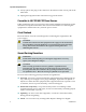
Using the Main Configuration Screen Using the Main Configuration Screen Press Enter at the prompt to display the main configuration screen.
Using the Main Configuration Screen Note: Reboot the Mini FiberLinX-II for changes to take effect. To reboot, type reboot at the prompt on the main configuration screen, or press Delete or F2 to power-cycle the chassis. Any changes to the configuration may result in a momentary loss of connection.
Using the Main Configuration Screen To Assign Trap Destinations Traps are sent by the manageable device to a management PC when a certain event takes place. To enter a trap destination, press T. At the “Enter a New IP Address.” prompt, enter the appropriate IP address and press Enter. Then, type the name of the community string (that the destination device has been configured to accept) and press Enter. This function enables ALL of the device traps.
Using the Main Configuration Screen To End the Session Be sure to press E to end a serial port or Telnet/HyperTerminal session, before disconnecting the cable. This will stop the continuous stream of data to the serial port. To Reboot the Module To reboot the Mini FiberLinX-II module, type reboot. To Enable or Disable DHCP To toggle DHCP on the Mini FiberLinX-II between enable and disable, press D.
Using the Main Configuration Screen The following table summarizes these options. Additional details on each option are provided below. Command Description cleandb Reboots the unit with a clean database. This removes all information from the database and sets the unit to factory defaults. download Downloads firmware via the TFTP protocol. ifStats Displays Ethernet statistics. rmStats Displays RMON statistics. version Displays the unit’s serial number and build date.
Using the Main Configuration Screen Downloading Files Firmware for the Mini FiberLinX-II can be downloaded from a central server via TFTP protocol. Initiate this download via serial configuration or Telnet session. Complete the following steps to download a file. 1 Type download and then press Enter. The Download a File screen opens, displaying the IP address of the TFTP server and the name of the file to be downloaded.
Using the Main Configuration Screen Viewing Port RMON Statistics To view port RMON (Remote MONitoring) statistics on the Mini FiberLinX-II, type rmstats and then press Enter. A screen opens displaying RMON information on packets received as defined in RFC 2819 for RMON. Note: If necessary, you can refresh the data on this screen by pressing the Space Bar. Version To display the current firmware version for the Mini FiberLinX-II, , type version and then press Enter.
Using the Main Configuration Screen Complete the following steps to define new security settings: 1 Type Y (or type any other key to abort). A screen appears allowing you to configure ARP settings, such as the destination address of ARP messages, along with Ethernet Types. 2 Enter the new data. 3 Type S to save the new security settings (or type Q to cancel). Port Configuration Serial/Telnet sessions display port status as well as allowing configuration of some port features.
Using the Main Configuration Screen Operational Mode Configuration As referenced in Product Applications, there are six modes of operation that can be configured through the Serial/Telnet session. All of the modes of operation will block management traffic on the Data port. To access the configuration screen, type config and then press Enter from the Additional Commands screen. Mode One – Default and Default Plus The default mode is designed to pass untagged traffic only.
Using the Main Configuration Screen Mode Two - Transparency with Untagged Management This mode is designed to pass all tagged and extra-tagged customer traffic unchanged and must be managed using untagged traffic only. It does not add or remove tags. Select Y on the initial config screen, and from the Transparent Mode Setup screen, select N in the fields.
Using the Main Configuration Screen Mode Three - Transparency with Tagged Management This mode will pass all tagged and untagged customer traffic. Management traffic must be tagged. It does not add or remove tags. Select Y on the initial config screen, and from the Transparent Mode Setup screen, select Y and enter the Management Tag.
Using the Main Configuration Screen Mode Four - Transparency with Extra Tagging (or Q-in-Q) This mode is designed to either pass all customer traffic with the defined extra tag (Q-in-Q) or add and remove the defined extra tag (Q-in-Q) on all customer traffic. Management traffic can be tagged or untagged. Select Y on the initial config screen, and then select Y when asked to select Extra Tags.
Using the Main Configuration Screen Mode Five - VLAN Filter This mode is designed to only pass traffic with any of the 32 tags that have been identified in the user-defined table. No untagged traffic can pass and management traffic must be tagged. No tags are added or removed from the traffic. Select N on the initial config screen, and then set up the VLAN screen. Note: VLAN IDs can be any number between 1 and 4,094.
Using the Main Configuration Screen The following table shows how the settings are entered. Setting VLAN Priority Tags Optical - - Yes Data Tag2 4 No Mgmt (SNMP) Tag1 1 Yes System Description (Sysdescr) Sysdescr offers the options of assigning a system name, System Contact System Location, Unit Description, and individual Port names. To assign each of these values, type the description or name, up to 32 characters per line, in the field provided.
Using the Main Configuration Screen Note: This feature requires firmware version B2 or higher. Use the arrow keys to navigate and the Space Bar to change the values on this screen. The following table describes the settings available on this screen. Setting Description Unit FlowControl Enable/Disable FlowControl. Unit FiberAlert Enable/Disable FiberAlert. Unit Loopback Enable/Disable the various LoopBack testing modes.
Using the Main Configuration Screen To log onto the unit through the serial port, connect a PC to the Mini FiberLinX-II using the included adapter. Set the computer or terminal for VT-100 emulation, and apply the following communication settings: 38.4K baud 8 data bits 1 stop bit No parity No FlowControl Enter the User Name and Password as admin (the default setting) when connecting through Telnet/HyperTerminal. We recommend setting a new User Name and Password after signing on for the first time.
Using the Main Configuration Screen When there is no DHCP server on the network, use iConfig or serial configuration to set the IP addresses manually. When DHCP is enabled, the IP address (default 10.10.10.10 or user configured) is saved. When DHCP is disabled, the saved IP address will be reinstated and the device will reboot. DHCP servers give out lease times, and devices renew their leases based on the administrator-specified time.
Using PrismaView Using PrismaView PrismaView software provides network management in an easy-to-use GUI format. After installing PrismaView on a network management PC using a Windows operating system, you can access PrismaView using the Windows Start menu. Note: Windows SNMP services must be installed to receive traps. The left side of the PrismaView screen displays the Prisma FiberLinX products on the network. To open the PrismaView screen for this module, click the connection for Mini FiberLinX-II.
Using PrismaView Option Description Bandwidth Displays the Bandwidth Limitation Settings. Port Desc Displays a screen for setting port descriptions. Each name should not exceed 32 characters or include any spaces. Tables Displays a screen for viewing statistics tables regarding network performance. Advanced Displays the Mini FiberLinX-II advanced settings. Agent Info Information about the SNMP Management software is displayed here.
Configuration File Save/Restore Function Configuration File Save/Restore Function The Configuration File Save/Restore function lets you back up all of the configuration settings of a unit. You can use this backup to restore settings to a unit if necessary or apply the same settings to a different unit. Overview All configurable managed objects are saved in a configuration file stored in the Large File Area of the module.
Configuration File Save/Restore Function 4 The Save As dialog window opens, prompting you for a file name. 5 Type the file name, and then click Save. A new dialog prompts you for any notes to be added to the header of the saved file for future reference when uploading the file through iConfig. 6 Type any notes to be added to the header of the file, and then click OK. After the file transfers from the module to disk, you are notified of the status.
Configuration File Save/Restore Function To Upload a Saved Configuration File Using iConfig Complete the following steps to upload a saved configuration file using iConfig. 1 Log into the module through iConfig. 2 Select the Administration tab. 3 From the iConfig Administration tab, click Upload Configuration. 4 The Select Config File dialog window appears, prompting you to select a configuration file. 5 Select the appropriate configuration file, and then click OK. The file upload process begins.
Configuration File Save/Restore Function Note: By default, the new configuration file does not overwrite the current module IP address configuration. To Upload a Saved Configuration File Using TFTP Complete the following steps to upload a saved configuration file using TFTP. 52 1 Log into the unit either through a serial port session or through Telnet. The CLI commands list appears. 2 Type download and then press Enter to run the Download command. The download command screen appears.
Configuration File Save/Restore Function 3 Type the IP address of the TFTP server and the name of the file to be retrieved, and then press Enter. A "ready" prompt appears. 4 Press Enter (or Return) to initiate the file transfer process (or press Q to cancel). After the transfer process is complete, you are again prompted to press Enter (or Return) to load the configuration file. 5 Press Enter (or Return) to load the configuration file (or press Q to cancel).
Product Applications Product Applications The Mini FiberLinX-II comes with a variety of features for different network environments. When used with different types of IMC Products, some features can be enabled, such as extra tagging or “Q-in-Q,” and different network setups come with different requirements. The network setup example below shows one deployment scenario with a full range of management options.
Modes of Operation Modes of Operation The following are application examples of Operation Modes for the Mini FiberLinXII. There are six modes of operation that can be configured through the Serial/Telnet session. All modes of operation block management traffic from the user network on the Data port. Mode One - Default The default mode is provided to pass only untagged traffic. Default Plus The Default Mode Plus allows tagged and untagged traffic to pass between the data and optics ports.
Modes of Operation Mode Three - Transparency with Tagged Management This mode will pass all tagged and untagged customer traffic. Management traffic must be tagged. It does not add or remove tags. Mode Four - Transparency with Extra Tagging (or Q-in-Q) This mode is designed to either pass all customer traffic with the defined extra tag (Q-in-Q) or add and remove the defined extra tag (Q-in-Q) on all customer traffic. Management traffic can be tagged or untagged.
Modes of Operation Note: VLAN IDs can be any number between 1 and 4,094. Mode Six - Port VLAN This mode tags all customer traffic received by the copper port going to the fiber port, untagging traffic conversely. Management traffic must be tagged.
Troubleshooting Troubleshooting If a fiber connection cannot be established, perform the following steps to confirm that the fiber transceivers on the Mini FiberLinX-II are not over- or under-driving the fiber receivers: 1 Make sure that the fiber wavelength on both connected devices match (i.e. both are 1310 nm single-mode fiber). 2 Make sure that FiberAlert is enabled on only one unit when connecting a Mini FiberLinX-II to another IMC Networks media converter with the FiberAlert feature.
Mini FiberLinX-II Modes of Operation Mini FiberLinX-II Modes of Operation 4030542 Rev B 59
Fiber-Optic Cleaning Guidelines Fiber-Optic Cleaning Guidelines CAUTION: Proper operation of this equipment requires clean optical fibers. Dirty fibers will adversely affect performance. Proper cleaning is imperative. The proper procedure for cleaning optical connectors depends on the connector type. The following describes general instructions for fiber-optic cleaning. Use your company's established procedures, if any, but also consider the following.
Fiber-Optic Cleaning Guidelines To Clean Optical Connectors Warning: Avoid personal injury! Use of controls, adjustments, or procedures other than those specified herein may result in hazardous radiation exposure. Avoid personal injury! The laser light source on this equipment (if a transmitter) or the fiber cables connected to this equipment emit invisible laser radiation.
For Information For Information Support Telephone Numbers This table lists the Technical Support and Customer Service numbers for your area.
For Information Region Centers Telephone and Fax Numbers Mexico, Central America, Caribbean Mexico For Technical Support, call: Telephone: 52-3515152599 Fax: 52-3515152599 For Customer Service or to request an RMA number, call: Telephone: 52-55-50-81-8425 Fax: 52-55-52-61-0893 E-mail: karla.lugo@sciatl.
5030 Sugarloaf Parkway, Box 465447 Lawrenceville, GA 30042 678.277.1000 Cisco, Cisco Systems, the Cisco logo, the Cisco Systems logo, Prisma, PrismaView, and MediaCenter are registered trademarks or trademarks of Cisco Systems, Inc. and/or its affiliates in the U.S. and certain other countries. All other trademarks mentioned in this document are the property of their respective owners. Product and service availability are subject to change without notice. © 2009 Cisco Systems, Inc. All rights reserved.