USER GUIDE BUSINESS SERIES Business Internet Camera with Audio Model: PVC2300, WVC2300
About This Guide About This Guide Icon Descriptions While reading through the User Guide you may encounter various icons designed to call attention to a specific item. Below is a description of these icons: Open Source This product may contain material licensed to you under the GNU General Public License or other open-source software licenses. Upon request, open-source software source code is available at cost from Linksys for at least three years from the product purchase date.
Table of Contents Chapter 1: Introduction 1 Minimum Requirements . . . . . . . . . . . . . . . . . . . . . . . . . . . . . . . . . . . . . . . . . . 1 Chapter 2: Wireless Security Checklist 2 General Network Security Guidelines . . . . . . . . . . . . . . . . . . . . . . . . . . . . . . . . . 2 Additional Security Tips . . . . . . . . . . . . . . . . . . . . . . . . . . . . . . . . . . . . .
Table of Contents Setup > Advanced Setup . . . . . . . . . . . . . . . . . . . . . . . . . . . . . . . . . . . . . . . . 21 HTTP/HTTPS . . . . . . . . . . . . . . . . . . . . . . . . . . . . . . . . . . . . . . . . . . . . . 21 RTP/RTSP . . . . . . . . . . . . . . . . . . . . . . . . . . . . . . . . . . . . . . . . . . . . . . . 22 UPnP . . . . . . . . . . . . . .
Table of Contents Output Ports Manual Control . . . . . . . . . . . . . . . . . . . . . . . . . . . . . . . . . . . 31 Applications > RS-485 . . . . . . . . . . . . . . . . . . . . . . . . . . . . . . . . . . . . . . . . . . 31 Port Settings . . . . . . . . . . . . . . . . . . . . . . . . . . . . . . . . . . . . . . . . . . . . . 31 Preset Position . . . . . . . . . . . . . .
Table of Contents Safety Notices . . . . . . . . . . . . . . . . . . . . . . . . . . . . . . . . . . . . . . . . . . . . . . . 51 Industry Canada Statement . . . . . . . . . . . . . . . . . . . . . . . . . . . . . . . . . . . . . . . 51 Industry Canada Radiation Exposure Statement: . . . . . . . . . . . . . . . . . . . . . . 51 Avis d’Industrie Canada . . . . . . . . . . . . . . . . .
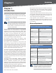
Introduction Chapter 1 Chapter 1: Introduction With extensive feature support like IP Multicast, RTSP, RTP, and 3GPP, video can be viewed from multiple endpoints and client applications like 3G phones, and Quicktime clients on PCs or Wi-Fi phones. Thank you for choosing the Linksys Business Internet Video Camera with Audio. This User Guide covers two models: Support for multiple network protocols like 802.1p priority, 802.
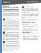
Wireless Security Checklist Chapter 2 Chapter 2: Wireless Security Checklist Wireless networks are convenient and easy to install, so businesses with high-speed Internet access are adopting them at a rapid pace. Because wireless networking operates by sending information over radio waves, it can be more vulnerable to intruders than a traditional wired network. Like signals from your cellular or cordless phones, signals from your wireless network can also be intercepted.
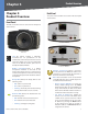
Product Overview Chapter 3 Chapter 3: Product Overview Back Panel The ports and reset button are located on the back panel of the Camera. Front Panel The LEDs and Camera lens are located on the front panel of the Camera. Back Panel - PVC2300 Front Panel Lens The Camera includes a removable CS‑mount lens. For specifications on the included lens, refer to the Specifications section of this User Guide. For a list of recommended lenses to use with this Camera, please refer to the Quick Installation Guide.
Product Overview Chapter 3 Ethernet The Ethernet port supports network speeds of either 10 Mbps or 100 Mbps, and can operate in half and full-duplex mode. PVC2300 PoE LED This LED only functions on the PVC2300 Camera. The LED has the following states: Auto-sensing technology enables the port to automatically detect the speed of the device connected to it (10 Mbps or 100 Mbps), and adjust its speed and duplex accordingly. On PoE connection is detected.
Installation Chapter 4 Chapter 4: Installation Overview This chapter will explain how to install the Camera into a wired or wireless network. The following diagrams show some typical network configurations. Linksys Wired Network Linksys One Ready When the Camera is connected to a Linksys One network, you can access the images using the Linksys One Video Surveillance Application (VSA) from any PHM1200 IP phone or web browser. The Linksys One VSA is a zero configuration plug-and-play application.
Installation Chapter 4 Linksys One Wireless Network 2. Connect the camera stand to the bottom of the camera. Adjust the camera to the appropriate viewing position. Locknut Once the camera is positioned properly, secure the camera in place by tightening the locknut. 3. Connect the included Ethernet network cable to your network router or switch.
Installation Chapter 4 Configuration 1. Insert the Setup CD into your CD‑ROM drive. If the CD doesn’t run automatically, go to My Computer and click on your CD-ROM drive. Verify that the Camera’s LEDs are lit. 2. The Setup screen will appear. Click the Click Here to Start button.
Installation Chapter 4 If the Camera you want is not displayed in the Selection box, click Search Again. NOTE: The Camera defaults to DHCP mode. If your network doesn’t have a DHCP server or if you are having issues obtaining an IP address, you can assign a static IP address to the Camera by pressing the reset button for less than 10 seconds. A static IP address of 192.168.1.99 will be assigned to the Camera. Reset Button – Camera Name Enter a unique name for the Camera, up to 15 characters in length.
Installation Chapter 4 14. Click the Install button. A timer will appear as the settings are saved to the Camera. 10. A window will appear indicating that the settings have been saved successfully. Click OK to continue. You should be able to view video on the home page. 11. The Wizard will now return to the Welcome screen. Click Exit to automatically launch your default web browser and proceed to the Home page login screen. Setting Up the Wireless Connection on the WVC2300 Camera 12.
Installation Chapter 4 Wireless Security WPA /WPA2 Enterprise Security Mode Select the appropriate option based on your wireless network configuration: The screen options vary depending upon the protocol type selected. • Disabled This option implements no security on your wireless network. Data is not encrypted before transmission. • WEP WEP is a basic encryption method, which is not as secure as later methods such as WPA-Personal or WPA2 Personal. However, it is supported by all clients.
Chapter 4 • Password This is for this Camera’s client login to the RADIUS server. • Anonymous ID The unsigned public ID used for login to your RADIUS server.
Chapter 5 Installing and Using the Viewer and Recorder Software Chapter 5: Installing and Using the Viewer and Recorder Software 3. The Choose Destination Location screen will appear. To install the Viewer & Recorder Utility files in the default folder, click the Next button. To select a different folder, click the Browse button and follow the on‑screen directions. Overview This chapter will instruct you on how to install and use the Internet Camera Viewer & Recorder Utility on your PC.
Chapter 5 Installing and Using the Viewer and Recorder Software Using the Monitor Application Viewing When a Camera has a green light under this icon, it indicates the video is being viewed. After the software has been installed, you can launch the application from shortcuts on the desktop and in the Start menu. Recording When a Camera has a red light under this icon, it indicates that video is being recorded. Motion When a Camera has a light under this icon, it indicates that motion has been detected.
Chapter 5 Installing and Using the Viewer and Recorder Software Snapshot Clicking this captures an image from the current video. Zoom Clicking this magnifies a section of the window. Click the icon and then click the portion of the screen you want to magnify. Click the icon again to return magnification to normal. Several setup options appear on the left-hand side of the screen. They are Camera Setup, Recording Schedule, and Preferences.
Chapter 5 Installing and Using the Viewer and Recorder Software 6. Click Exit to return to the Video Monitor screen. Deleting a Camera You can delete any of the sixteen cameras displayed from the Setup screen by doing the following: 2. Click the line you wish to assign to the schedule in the box at the top of the screen. 3. Click the Add button to schedule the recording. Deleting a Schedule 1. Select the camera you want to delete from the list in the box at the top of the screen.
Chapter 5 Installing and Using the Viewer and Recorder Software Record after Motion Detected Set the time so the Utility will stop recording a certain time after the Utility detects motion in a Camera’s field of view. Disk Allocation for Recording Total Disk Space This shows the total amount of storage space on your hard drive. Available Disk Space This shows the amount of storage space available on your hard drive.
Chapter 5 Installing and Using the Viewer and Recorder Software Zoom Out This button is used to zoom out the view. Print This button is used to print the image. Playback Speed This slide bar allows you to adjust the speed of the video playback. Audio Controls This slide bar allows you to control the volume level. Sound On/Off Toggles the sound on or off. Hard Disk Quota Free Space Displays the amount of available space on the hard disk. Used Space Displays the total amount of space used on the hard disk.
Advanced Configuration Chapter 6 Chapter 6: Advanced Configuration Home The Home screen is where live video can be viewed and the output can be updated. NOTE: By default the camera is set to receive an IP address from a DHCP server. If you do not have a DHCP server on your network, you can set a static IP address by pressing the Reset button on the camera for less than 10 seconds. A default IP address of 192.168.1.99 will be assigned to the camera.
Advanced Configuration Chapter 6 Resolution PC’s Date and Time Displays the current time of the PC connected to the web-based utility. Setup > Basic Setup Camera Date and Time Displays the current time as configured on the camera. Sync with PC This option allows you to synchronize the camera to the clock on the PC connected to the web‑based utility. New Date This option allows you to manually enter the date for the camera.
Advanced Configuration Chapter 6 IP Address The IP address assigned to the Camera is displayed. TX Key Select the number of the key used on the wireless network. Subnet Mask The Subnet Mask assigned to the Camera is displayed. WEP Encryption Select the appropriate option for key length based on your network settings. Gateway IP address of the gateway router between this device and management stations that exist on other network segments.
Advanced Configuration Chapter 6 • certificate, which implies that you trust your browser’s publisher to include correct user certificates, and in turn the certificate authorities it trusts, and only user to whom the CA may have issued a certificate-issuingcertificate, to faithfully authenticate the users of all their certificates. HTTP/HTTPS Password This is for this Camera’s client login to the RADIUS server, and must match the key stored on the RADIUS server.
Advanced Configuration Chapter 6 2. Enter the IP address of your router in your web browser’s Address field and press Enter. In this example, the default IP address of the WRT54G router is used (192.168.1.1). 3. Enter the login name and password to access the router’s web-based utility. 4. In the web-based utility, go to the Applications & Gaming tab. RTSP Port Enter the RTSP Port number (between 1024 to 65535) in the field provided. The default RTSP port is 554.
Advanced Configuration Chapter 6 QoS • Enable QoS Mode QoS (Quality of Service) mode is disabled by default. To enable QoS mode, select this option and select either audio or video for its guaranteed throughput level. Enable QoS mode will automatically enable WMM (802.11e QoS) when in wireless mode. Enable and Allow the Following IP Address This option will allow only the IP addresses specified here to access the camera.
Chapter 6 Privilege Level Select the appropriate privilege level from the drop-down menu. Choose from one of the following options: • Administrator This option provides the specified user with full Camera administration and control privileges. • Monitor This option grants the specified user with control of the Camera video (manually pan/tilt, toggle between day/night vision, and trigger output ports). • Viewer This option grants the specified user with video viewing privileges only.
Advanced Configuration Chapter 6 NOTE: Higher video quality settings and higher frame rate settings require more bandwidth. Refer to the Appendix titled “Bandwidth Usage” for additional details. MPEG-4 Settings Resolution Select the desired video resolution setting. The default resolution is set to 320x240. Video Quality Control Choose one of the following: • Constant Bit Rate Select the desired fix bit rate. The default bit rate is set to 256 Kbps. • Fix Quality Select the desired fix quality.
Advanced Configuration Chapter 6 Audio/Video > Audio 0 - 479 Y Coordinate X Coordinate 0 - 639 Image Position • Transparent Color This option allows you to define a color that should appear transparent. This allows a logo or other image to appear over the video without displaying a solid background color. The color value must be entered in RGB hexadecimal color code, such as 0000ff. Audio/Video > Audio Audio Settings Enable Audio Enable audio by checking the check box.
Advanced Configuration Chapter 6 Applications > Mail & FTP Authentication Choose from one of the following options: • Not Required Authentication is not required in order to send mail. • Requires SMTP Authentication Select this if the SMTP Server requires a “login” to send mail. • Requires POP before SMTP Select this if the SMTP Server requires a POP “login” to send mail. E-mail Setup Send To Enter at least one (1) e-mail address; the 2nd and 3rd addresses are optional.
Advanced Configuration Chapter 6 Login Name Enter the login name associated with the secondary FTP server. NOTE: Motion detection can be triggered by rapid changes in lighting conditions, as well as by moving objects. For this reason, it should only be used indoors. Password Enter the password associated with the login name for the secondary FTP server. File Path Name Enter the desired file path name on the secondary FTP server.
Advanced Configuration Chapter 6 Setting Custom Area Enable this option to capture motion within defined areas of the video screen. Multiple windows with varied threshold settings may be used. • Window 2-4 Enable one or more of these options to detect motion in specific areas of the video screen. Windows can be defined by simply extending the window with the cursor. More than one window can be used at once. • Indicator This area displays the level of motion detected.
Advanced Configuration Chapter 6 Overwrite/Replace oldest video file Check to overwrite/ replace the oldest video clip with the current recording when detecting device’s SDRAM is full. Attachment Type Select the type of attachment: • • JPEG Image Select this to send image captures. – Frame Rate Select the desired capture rate for the JPEG image(s) here. – Pre/Post Capture Select the desired length.
Advanced Configuration Chapter 6 Output Ports State at Power On In the Camera, as long as both output’s Default and Current State is High, the output is disconnected (floating). When the current State changes to Low or Low Pulse, the output will be activated. Parity Select the desired parity type for the device you connected. Stop Bits Select the desired stop bits for the device you connected. # Displays the port number. Address Enter the valid logical address of the receiver/ driver being controlled.
Advanced Configuration Chapter 6 Status > System Image Quality This displays the image quality of the video stream. Frame Rate This displays the frame rate of the video stream. MJPEG Resolution This displays the image size of the video stream. Image Quality This displays the image quality of the video stream. Frame Rate This displays the frame rate of the video stream. Status > System Status > Network System Status Firmware Version The version of the firmware currently installed is displayed.
Advanced Configuration Chapter 6 SSID This displays the wireless network name (SSID) used by the camera. Status > Video Log Channel This displays the wireless channel used by the camera. Security This indicates if wireless security is being used by the camera. Status > Syslog & Log View Video Log Video Log Refresh Click this button to reload all the entries in the video log. Status > Syslog & Log Delete All Click this button to erase all the entries in the video log.
Troubleshooting Appendix A Appendix A: Troubleshooting The motion detection feature doesn’t send me any E‑mails. This appendix provides solutions to problems that may occur during the installation and operation of the Business Internet Video Camera. Read the questions and answers below to solve your problems: It may be that the SMTP (Simple Mail Transport Protocol) server used by the Camera to send the E-mail will not accept mail. This is to prevent Spam being sent from the server.
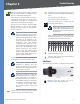
Bandwidth Usage Appendix B Appendix B: Bandwidth Usage WVC2300 Bandwidth Test Audio: ON One User viewing video Resolution Quality Very High 640 x 480 Normal Very Low Very High 320 x 240 Normal Very Low Very High 160 x 128 Normal Very Low Business Internet Video Camera with Audio Frame Rate Bandwidth (k/bps) MPEG-4 MJPEG 30 2320 3040 15 1840 2800 6 880 1840 30 2240 2800 15 1680 2640 6 640 1600 30 2160 2640 15 1200 2400 6 560 1200 30 1600 2000 15 1200 1600 6
Glossary Appendix C Appendix C: Glossary Baud Indicates the number of signaling elements transmitted each second. This glossary contains some basic networking terms you may come across when using this product. Bit A binary digit. WEB: For additional terms, please visit the glossary at www.linksys.com/glossary Access Mode Specifies the method by which user access is granted to the system. Access Point A device that allows wireless-equipped computers and other devices to communicate with a wired network.
Appendix C CoS (Class of Service) The 802.1p priority scheme. CoS provides a method for tagging packets with priority information. A CoS value between 0-7 is added to the Layer II header of packets, where zero is the lowest priority and seven is the highest. DDNS (Dynamic Domain Name System) Allows the hosting of a website, FTP server, or e-mail server with a fixed domain name (e.g., www.xyz.com) and a dynamic IP address. Default Gateway A device that forwards Internet traffic from your local area network.
Appendix C Glossary MAC (Media Access Control) Address The unique address that a manufacturer assigns to each networking device. RADIUS (Remote Authentication Dial-In User Service) A protocol that uses an authentication server to control network access. Mask A filter that includes or excludes certain values, for example parts of an IP address. RJ-45 (Registered Jack-45) An Ethernet connector that holds up to eight wires.
Appendix C Glossary TCP (Transmission Control Protocol) A network protocol for transmitting data that requires acknowledgement from the recipient of data sent. TCP/IP (Transmission Control Protocol/Internet Protocol) A set of instructions PCs use to communicate over a network. Telnet A user command and TCP/IP protocol used for accessing remote PCs. TFTP (Trivial File Transfer Protocol) A version of the TCP/IP FTP protocol that has no directory or password capability.
Specifications Appendix D Appendix D: Specifications PVC2300 Specifications Model PVC2300 Standards IEEE802.3, IEEE802.3u, IEEE802.1p (QoS Priority), IEEE802.
Specifications Appendix D Default Bit Rate 16Kbps Management Utility Monitoring and Recording software Recording set up to record by motion trigger, manual or schedule recording and playback Security Username/password Kensington lock Power Options User Rights List to View Video and/or to Camera Control Functions Logon authentication 20 character username and 8 character password Physical security option Network RTP/RTSP Real-Time Protocol, Real-Time Streaming Protocol allow for vi
Specifications Appendix D WVC2300 Specifications Model WVC2300 Standards IEEE802.11g, IEEE802.11b, IEEE802.3, IEEE802.3u, IEEE802.1p (QoS Priority), IEEE802.1q (VLAN), 802.
Specifications Appendix D Management Utility Monitoring and Recording software Power Power Options External Power Adapter: 12V/1A, 110~120V AC/60Hz, Switching Power Consumption 10W Monitoring and Recording for up to 16 cameras Advanced search histogram or by time and date Recording set up to record by motion trigger, manual or schedule recording and playback Power Power Options IEEE 802.3af Power over Ethernet (PoE) - 48V/0.
Specifications Appendix D I/O Port Specifications 10 9 8 7 6 5 4 3 2 1 I/O PIN Specifications PIN Function Description 1 12VDC Output With a maximum load of 100mA, this output to be used with an external device. 2 GND 3 Digital Input 1 Connect to high to activate (5V-12V) 4 Digital Output 1 With a maximum load of 100mA and maximum voltage of 12VDC, this output has an open-collector NPN transistor with the emitter connected to GND.
Appendix E Appendix E: Warranty Information Limited Warranty Linksys warrants to You that, for a period of one year (the "Warranty Period"), your Linksys Product will be substantially free of defects in materials and workmanship under normal use. Your exclusive remedy and Linksys’ entire liability under this warranty will be for Linksys at its option to repair or replace the Product or refund Your purchase price less any rebates. This limited warranty extends only to the original purchaser.
Appendix F Wired Product Regulatory Information Appendix F: Wired Product Regulatory Information Industry Canada Statement FCC Statement This product has been tested and complies with the specifications for a Class B digital device, pursuant to Part 15 of the FCC Rules. These limits are designed to provide reasonable protection against harmful interference in a residential installation.
Appendix F Wired Product Regulatory Information User Information for Consumer Products Covered by EU Directive 2002/96/EC on Waste Electric and Electronic Equipment (WEEE) Ceština (Czech) - Informace o ochraně životního prostředí pro zákazníky v zemích Evropské unie This document contains important information for users with regards to the proper disposal and recycling of Linksys products.
Appendix F Wired Product Regulatory Information Eesti (Estonian) - Keskkonnaalane informatsioon Euroopa Liidus asuvatele klientidele Français (French) - Informations environnementales pour les clients de l’Union européenne Euroopa Liidu direktiivi 2002/96/EÜ nõuete kohaselt on seadmeid, millel on tootel või pakendil käesolev sümbol , keelatud kõrvaldada koos sorteerimata olmejäätmetega. See sümbol näitab, et toode tuleks kõrvaldada eraldi tavalistest olmejäätmevoogudest.
Appendix F Wired Product Regulatory Information Lietuvškai (Lithuanian) - Aplinkosaugos informacija, skirta Europos Sąjungos vartotojams Nederlands (Dutch) - Milieu-informatie voor klanten in de Europese Unie Europos direktyva 2002/96/EC numato, kad įrangos, kuri ir kurios pakuotė yra pažymėta šiuo simboliu (įveskite simbolį), negalima šalinti kartu su nerūšiuotomis komunalinėmis atliekomis. Šis simbolis rodo, kad gaminį reikia šalinti atskirai nuo bendro buitinių atliekų srauto.
Appendix F Wired Product Regulatory Information Português (Portuguese) - Informação ambiental para clientes da União Europeia Slovenčina (Slovene) - Okoljske informacije za stranke v Evropski uniji A Directiva Europeia 2002/96/CE exige que o equipamento que exibe este símbolo no produto e/ou na sua embalagem não seja eliminado junto com os resíduos municipais não separados. O símbolo indica que este produto deve ser eliminado separadamente dos resíduos domésticos regulares.
Appendix G Wireless Product Regulatory Information Appendix G: Wireless Product Regulatory Information Safety Notices FCC Statement This device complies with Part 15 of the FCC Rules. Operation is subject to the following two conditions: (1) This device may not cause harmful interference, and (2) this device must accept any interference received, including interference that may cause undesired operation.
Appendix G Wireless Product Regulatory Information Avis d’Industrie Canada Avis de non-responsabilité concernant les appareils sans fil Cet appareil est conforme aux normes NMB003 et RSS210 d’Industrie Canada. L’utilisation de ce dispositif est autorisée seulement aux conditions suivantes : 1. il ne doit pas produire de brouillage et 2. il doit accepter tout brouillage radioélectrique reçu, même si ce brouillage est susceptible de compromettre le fonctionnement du dispositif.
Appendix G User Information for Consumer Products Covered by EU Directive 2002/96/EC on Waste Electric and Electronic Equipment (WEEE) This document contains important information for users with regards to the proper disposal and recycling of Linksys products.
Appendix G Wireless Product Regulatory Information Eesti (Estonian) - Keskkonnaalane informatsioon Euroopa Liidus asuvatele klientidele Français (French) - Informations environnementales pour les clients de l’Union européenne Euroopa Liidu direktiivi 2002/96/EÜ nõuete kohaselt on seadmeid, millel on tootel või pakendil käesolev sümbol , keelatud kõrvaldada koos sorteerimata olmejäätmetega. See sümbol näitab, et toode tuleks kõrvaldada eraldi tavalistest olmejäätmevoogudest.
Appendix G Wireless Product Regulatory Information Lietuvškai (Lithuanian) - Aplinkosaugos informacija, skirta Europos Sąjungos vartotojams Nederlands (Dutch) - Milieu-informatie voor klanten in de Europese Unie Europos direktyva 2002/96/EC numato, kad įrangos, kuri ir kurios pakuotė yra pažymėta šiuo simboliu (įveskite simbolį), negalima šalinti kartu su nerūšiuotomis komunalinėmis atliekomis. Šis simbolis rodo, kad gaminį reikia šalinti atskirai nuo bendro buitinių atliekų srauto.
Appendix G Wireless Product Regulatory Information Português (Portuguese) - Informação ambiental para clientes da União Europeia Slovenčina (Slovene) - Okoljske informacije za stranke v Evropski uniji A Directiva Europeia 2002/96/CE exige que o equipamento que exibe este símbolo no produto e/ou na sua embalagem não seja eliminado junto com os resíduos municipais não separados. O símbolo indica que este produto deve ser eliminado separadamente dos resíduos domésticos regulares.
Appendix H Contact Information Appendix H: Contact Information Linksys Contact Information Website http://www.linksys.com E-Mail support@linksys.com FTP Site ftp.linksys.com Advice Line 800-546-5797 (LINKSYS) Support 800-326-7114 RMA (Return Merchandise 949-823-3000 Authorization) Fax 949-823-3002 NOTE: Details on warranty and RMA issues can be found in the Warranty and Regulatory Information section of this Guide.