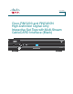
User Guide Cisco RNG200 and RNG200N High-Definition Digital-Only Interactive Set-Tops with Multi-Stream CableCARD Interface (Black) CH+ VOL- VOL+ POWER SELECT CH- MENU INFO EXIT LIST RNG200N
Notice to Installers The servicing instructions in this notice are for use by qualified service personnel only. To reduce the risk of electric shock, do not perform any servicing other than that contained in the operating instructions, unless you are qualified to do so. Note to System Installer For this apparatus, the coaxial cable shield/screen shall be grounded as close as practical to the point of entry of the cable into the building.
Contents Important Safety Instructions ........................................................................................................iv Welcome....................................................................................................................................... 1 Safety First ................................................................................................................................... 1 Identify Your Set-Top ....................................................
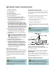
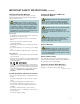
IMPORTANT SAFETY INSTRUCTIONS 1) Read these instructions. Outdoor Grounding System 2) Keep these instructions. If this product connects to an outdoor antenna or cable system, be sure the antenna or cable system is grounded (earthed). This provides some protection against voltage surges and builtup static charges. 3) Heed all warnings. 4) Follow all instructions. 5) Do not use this apparatus near water. 6) Clean only with dry cloth. Article 810 of the National Electric Code (NEC) ANSI/NFPA No.
IMPORTANT SAFETY INSTRUCTIONS, continued Handling Disposable Batteries This product may contain disposable batteries. Heed the following warning and follow the Battery Safety and Battery Disposal instructions below. WARNING: There is danger of explosion if the battery is mishandled or incorrectly replaced. Replace only with the same type of battery. Do not disassemble it or attempt to recharge it outside the system.
vi
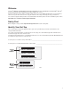
Welcome The Cisco® RNG200 and RNG200N High-Definition Digital-Only Set-Tops with Multi-Stream CableCARD™ (M-Card™) provide high-definition (HD) capability and broadband digital video services. Follow the instructions in this guide to install the DVR set-top, to become familiar with the buttons on the front panel, and to access your cable services. Then, enjoy the features of the set-top and change the way you watch TV. The consumer support website provides news and information about this product.
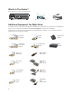
What’s In The Carton? The set-top carton contains the following items: CH+ VOL- VOL+ POWER SELECT CH+ CH- MENU INFO EXIT VOL- LIST VOL+ POWER RNG200N • RNG200 or RNG200N with M-Card SELECT CH- MENU INFO EXIT LIST RNG200N • Quick Reference Guide • Power Cord Additional Equipment You Might Need You might need some of the cables and adapters shown below for connecting the set-top to your home entertainment devices.
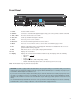
Front Panel CH+ VOL- VOL+ POWER SELECT MENU CH- INFO EXIT LIST RNG200N 1 2 3 4 5 6 7 8 9 10 11 T14761 1 Power Turns the DVR on and off 2 USB 2.
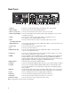
Back Panel OUTPUT STB SN: SABPQBQGD VIDEO DIGITAL AUDIO Y OPTICAL AUDIO OUT MULTI-STREAM CABLE CARD CAUTION RISK OF ELECTRIC SHOCK DO NOT OPEN AVIS: RISQUE DE CHOC eCM MAC: 001AC3F4F757 ELECTRIQUE NE PAS OUVRIR MCARD SN: PXCPRPSLV STB RF MAC: 001AC3F$F756 THIS DEVICE IS INTENDED TO BE ATTACHED TO A RECEIVER THAT IS NOT USED TO RECEIVE OVER-THE-AIR BROADCAST SIGNALS.
Connecting the Set-Top To connect your set-top to your entertainment devices, complete these steps. 1 Determine if your TV is HD or SD and whether it is wide screen (16:9) or standard screen (4:3). See page 11 for more information. 16 4 or 9 3 Make the connections for your TV and VCR as follows: 2 3 4 • If you are using an HDTV, see page 6 and the connection diagrams at the end of this guide. • If you are using an SDTV, see page 7 and the connection diagrams at the end of this guide.
Connections for an HDTV and VCR To use the set-top with an HDTV, you must make one of the following connections to view the HD content. In addition, you can make connections to a digital or analog VCR to record to a VCR tape. Refer to your TV and VCR user guides and the cabling diagrams in this guide for more detailed connection information. Note: The labeling on your set-top, HDTV, and VCR may vary slightly.
Connections for a Standard-Definition TV and VCR When using the set-top with an SDTV, you must make one of the following connections to view content. Some SDTVs may not have all these connections. In addition, you can make connections to a VCR to record to a VCR tape. Refer to your TV and VCR user guides and the cabling diagrams in this guide for more detailed information. Note: The labeling on your set-top, SDTV, and VCR may vary slightly.
View Television Programming Access Services and Programs Access cable services and programs by pressing the following keys on the remote control: • Guide–Access the on-screen guide. The on-screen guide displays schedules of TV programs and other services available from your cable service provider, such as video-on-demand and pay-per-view programs. • Arrows–Select a program in the schedule. • Info–Display a specific program description (either from the on-screen guide or while viewing a program).
Troubleshooting If the set-top does not perform as expected, the following tips may help. If you need further assistance, contact your service provider. No Picture • Verify that the power to your TV is turned on. • Verify that your HDTV is in HD mode. If necessary, run the HD Setup Wizard to select HD mode. • If the set-top is plugged into a wall switch, verify that the switch is in the ON position. Note: You should avoid plugging the set-top into an outlet controlled by a wall switch.
Frequently Asked Questions What is Digital Television? Digital television (DTV) is a huge leap forward in television technology compared to analog television that has been widely available since the 1940s. DTV is delivered and displayed using digital encoding, similar to the way a PC operates. By using digital technology, there is no variation in picture and sound quality from the origination point until it is displayed on your television.
Picture Formats What is the Difference Between a Standard-Screen and a Wide-Screen HDTV? The type of screen your HDTV has (wide screen or standard screen) determines how the set-top displays programs on the screen. The picture format for an HDTV is a combination of aspect ratio and screen resolution and is different for standard-screen and wide-screen HDTVs. What is Aspect Ratio? An aspect ratio is the ratio of the width to the height of the TV screen.
Connecting to an HDTV with an HDMI Connector WARNING: Electric shock hazard! Unplug all electronic devices before connecting or disconnecting any device cables to the set-top.
Connecting to an HDTV with a DVI Connector WARNING: Electric shock hazard! Unplug all electronic devices before connecting or disconnecting any device cables to the set-top.
Connecting to an HDTV with Component Input (YPbPr) WARNING: Electric shock hazard! Unplug all electronic devices before connecting or disconnecting any device cables to the set-top.
Connecting to a Home Theater System with Component Input (YPbPr) WARNING: Electric shock hazard! Unplug all electronic devices before connecting or disconnecting any device cables to the set-top.
Connecting to a Stereo VCR and HDTV (optional) WARNING: Electric shock hazard! Unplug all electronic devices before connecting or disconnecting any device cables to the set-top.
Connecting the Set-Top in HD Mode to an SDTV with Component Input (YPbPr) WARNING: Electric shock hazard! Unplug all electronic devices before connecting or disconnecting any device cables to the set-top.
Connecting an External SATA Hard Disk Drive (optional) Complete the following steps to install an external SATA (eSATA) drive. 1. Verify that both the DVR and the eSATA drive are unplugged from power. 2. Connect the data cable for the eSATA drive to the DVR. 3. Plug in power to the eSATA drive. 4. Plug in the DVR power cord, and then turn on the DVR. 5. Follow the on-screen instructions. One of the following occurs: • If it is a new eSATA drive or one used on another device, you will be asked to format it.
Connecting an External SATA Hard Disk Drive (optional), continued Recommendations for the eSATA Drive Support for eSATA may vary by service provider. At a minimum, your eSATA drive should have the following capabilities: • External SATA Connector – SATA II Cable and Connector, Revision 1.0 (Refer to www.sata-io.org for more information) • Drive Speed – 7200 RPM (5400 RPM without Multi-RoomTM DVR); 133 Mbps • Capacity – Only one eSATA drive can be connected to the DVR.
Index A D AC Dashes display Outlet Diagrams.
Index, continued K S Keys. See Front panel; Back panel S-Video Safety L 6, 7 ii, iv-v Scan rates LED Display 3 11 Screen burn-in 8 M resolution M-Card. See Multi-Stream CableCARD size Multi-Stream CableCARD 1, 2, 4, 9 11 11 SD mode 5, 17 SDTV P Connections Picture What is it Doesn’t display 7, 17 10 Serial number, locating 9 Formats 11 Set-top. See Welcome No color 9 Software updates 9 Sound, troubleshooting Ports.
Index, continued U Updating software USB port 9 3 V VCR connection 6, 7, 16 View programs 8 W Watch TV 1, 8 Web access to product information Welcome 1 Widescreen TV 11 Y YPbPr connector 4, 6, 7 HDTV connection 14 home theater connection SDTV connection Z Zoom picture 22 8, 11 17 15 1
23
Software and Firmware Use FCC Compliance United States FCC Compliance This device has been tested and found to comply with the limits for a Class B digital device, pursuant to part 15 of the FCC Rules. These limits are designed to provide reasonable protection against such interference in a residential installation. This equipment generates, uses, and can radiate radio frequency energy. If not installed and used in accordance with the instructions, it may cause harmful interference to radio communications.
25
Cisco Systems, Inc. 5030 Sugarloaf Parkway, Box 465447 Lawrenceville, GA 30042 678.277.1000 www.cisco.com Cisco and the Cisco Logo are trademarks or registered trademarks of Cisco and/or its affiliates in the U.S. and other countries. A listing of Cisco’s trademarks can be found at www.cisco.com/go/trademarks. CableCARD and M-Card are trademarks of Cable Television Laboratories, Inc. Manufactured under license from Dolby Laboratories. Dolby is a trademark of Dolby Laboratories.