
Getting Started Guide

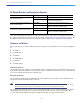

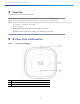
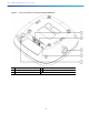
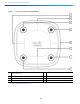
Table Of Contents
- Cisco Catalyst 9120AX Series Access Points
- 1 About this Guide
- 2 About the Access Point
- 3 Safety Instructions
- 4 Unpacking
- 5 AP Views, Ports, and Connectors
- 6 Preparing the AP for Installation
- 7 Installation Overview
- 8 Performing a Pre-Installation Configuration
- 9 Mounting the Access Point
- 10 Grounding the Access Point
- 11 Powering the Access Point
- 12 Configuring and Deploying the Access Point
- 13 Self-Identifying Antennas
- 14 Checking the Access Point LEDs
- 15 Miscellaneous Usage and Configuration Guidelines
- 16 FAQs
- 17 Related Documentation
- 18 Declarations of Conformity and Regulatory Information
- Manufacturers Federal Communication Commission Declaration of Conformity Statement
- VCCI Statement for Japan
- Guidelines for Operating Cisco Catalyst Access Points in Japan
- Statement 371—Power Cable and AC Adapter
- Industry Canada
- Canadian Compliance Statement
- European Community, Switzerland, Norway, Iceland, and Liechtenstein
- Declaration of Conformity for RF Exposure
- Generic Discussion on RF Exposure
- This Device Meets International Guidelines for Exposure to Radio Waves
- This Device Meets FCC Guidelines for Exposure to Radio Waves
- This Device Meets the Industry Canada Guidelines for Exposure to Radio Waves
- Cet appareil est conforme aux directives internationales en matière d'exposition aux fréquences radioélectriques
- Additional Information on RF Exposure
- Administrative Rules for Cisco Catalyst Access Points in Taiwan
- Operation of Cisco Catalyst Access Points in Brazil
- Declaration of Conformity Statements
- Communications, Services, and Additional Information
- Cisco Bug Search Tool

10
Cisco Catalyst 9120AX Series Access Points
Figure 3 Face of the 9120AXE and 9120AXE Models
1
Location of the 4-port Smart Antenna (DART) connector,
under a mylar cover
5
USB 2.0 port, under a mylar cover
2
Location of the ports and connectors on the head of the AP.
6
Status LED
3
RP-TNC antenna connector port (Dual-band A)
1
1. Self Identifying Antenna compatible RP-TNC connector port. For more information on Self Identifying Antennas, see “What
are Self Identifying Antennas?” section.
7
RP-TNC antenna connector port (Dual-band C)
4
RP-TNC antenna connector port (Dual-band B)
8
RP-TNC antenna connector port (Dual-band D)