Route Switch Processor (RSP2) Installation and Configuration Guide Product Numbers: RSP2, RSP=, ROMMON-RSP2, MEM-RSP-8M=, MEM-RSP-16M=, MEM-RSP-24M=, MEM-RSP-32M=, MEM-RSP-64M=, MEM-RSP-128M=, MEM-RSP-FLC8M=, MEM-RSP-FLC16M=, MEM-RSP-FLC20M=, MEM-RSP-FLC32M= Customer Order Number: DOC-782026= This document describes the Route Switch Processor (RSP2), the default system processor for the Cisco 7505, Cisco 7507 and Cisco 7513 routers.
• Configuring High System Availability, page 23 • Enabling High Availability Features, page 38 • Troubleshooting the Installation, page 60 • Reference Information, page 76 • Obtaining Documentation, page 85 • Obtaining Technical Assistance, page 86 • Obtaining Additional Publications and Information, page 88 Related Documentation All of the documentation mentioned below is available online, on the Documentation CD-ROM, or as printed documents.
– Obtaining Technical Assistance, page 86 – Obtaining Additional Publications and Information, page 88 Product Description This section discusses the following topics: • CPU, page 4 • Memory Components, page 5 • LEDs, page 6 • PC Card Slots, page 7 • Serial Ports, page 7 • Specifications, page 7 • System Software, page 8 The RSP2 supports the VIP2 and the VIP4 in the Cisco 7505, Cisco 7507, and the Cisco 7513. (See Figure 1 and Figure 2.
Providing Simple Network Management Protocol (SNMP) management and the interface between the console and Telnet • The high-speed switching section of the RSP2 communicates with and controls the interface processors on the high-speed CyBus. This switching section decides the destination of a packet and switches it based on that decision. The RSP2 uses a 16-million-instructions-per-second (mips) processor to provide high-speed, autonomous switching and routing.
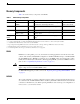
Memory Components Table 1 shows the memory components on the RSP2.
Caution Before you replace an RSP2 in a system with one RSP2, back up the running configuration to a TFTP file server or to Flash memory so you can retrieve it later. If the configuration is not saved, the entire configuration will be lost—inside the NVRAM on the removed RSP2—and you will have to reenter the entire configuration manually. For instructions on how to save the configuration file, see the “Saving and Retrieving the Configuration File” section on page 66.
2. If both the Master and Slave LEDs are unlite, the board is inactive. The Active/Standby switch has been deactivated in software. The reset button boots the system. PC Card Slots The RSP2 has two PC Card slots available. Either slot can support a Flash memory card or an input/output (I/O) device. Type I and Type II PC Cards can be used in PC Card slot 0 and slot 1. Type III PC Cards can be used in slot 1.
System Software The Cisco 7505, Cisco 7507, and Cisco 7513 routers support downloadable system software and microcode for most Cisco IOS software and microcode upgrades. This enables you to remotely download, store, and boot from a new image. The publication Upgrading Software and Microcode in Cisco 7000 Series and Cisco 7500 Series Routers (DOC- 781144=) provides instructions for upgrading over the network or from floppy disks. Flash memory contains the default system software.
Safety Guidelines This section lists safety guidelines you should follow when working with any equipment that connects to electrical power or telephone wiring. Warning Only trained and qualified personnel should be allowed to install or replace this equipment. Safety Guidelines Following are safety guidelines that you should follow when working with any equipment that connects to electrical power or telephone wiring. Safety Warnings Warning This warning symbol means danger.
Warnung Avvertenza Advarsel Aviso Dieses Warnsymbol bedeutet Gefahr. Sie befinden sich in einer Situation, die zu einer Körperverletzung führen könnte. Bevor Sie mit der Arbeit an irgendeinem Gerät beginnen, seien Sie sich der mit elektrischen Stromkreisen verbundenen Gefahren und der Standardpraktiken zur Vermeidung von Unfällen bewußt.
• Do not perform any action that creates a potential hazard to people or makes the equipment unsafe. • Carefully examine your work area for possible hazards such as moist floors, ungrounded power extension cables, and missing safety grounds. Telephone Wiring Guidelines Use the following guidelines when working with any equipment that is connected to telephone wiring or to other network cabling: • Never install telephone wiring during a lightning storm.
Compatibility Requirements This section describes important compatibility requirements for the RSP2. Chassis Slot and DRAM Requirements Following are chassis slot and DRAM requirements for ensuring RSP2 compatibility. • You have no restrictions on installing an RSP2 in a Cisco 7505. However, the Cisco 7505 does not support the HSA or the HA features. • You have no restrictions on installing an RSP2 in a Cisco 7507 provided that you install the RSP2 in slot 2 or slot 3, or both.
Software Prerequisites The minimum supported Cisco IOS release compatible with the RSP2 is 10.3(6) or a later release of Cisco IOS release 10.3. For the latest compatible software releases, refer to the software advisor at http://www.cisco.com/cgi-bin/Support/CompNav/Index.pl. Note The 32-MB Flash memory card is compatible with Cisco IOS Release 12.1(5)T1 or a later release of Cisco IOS Release 12.1 T.
Note Overriding the bundle can result in incompatibility among the various interface processors in the system. We recommend that you use only the microcode image that is bundled. The exception to this is CIP microcode, which as of Cisco IOS Release 11.1(1), is unbundled from the IOS software image bundle, and is available in a separate bundle on floppy disks, a TFTP server, CCO, or Flash memory cards. Installing the RSP2 The following sections describe the procedures for installing or replacing an RSP2.
• ESD-prevention equipment or the disposable ESD-preventive wrist strap included with all spares and upgrade kits. • Antistatic mat, foam pad, or bag for the removed RSP2 (place the removed RSP2 into an antistatic bag if you plan to return it to the factory, or on an antistatic mat or foam if you are replacing components and will reinstall the RSP2). • DRAM SIMMs from Cisco if you are replacing SIMMs.
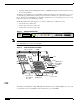
Figure 3 Ejector Levers and Captive Installation Screw Bottom ejector lever a Processor module carrier guide Processor module slot Captive installation screw c b H1482a STOP! on contact Step 7 Place the removed RSP2 on an antistatic mat or foam. If you plan to return the RSP2 to the factory, immediately place it in an antistatic bag to prevent ESD damage.
Replacing the RSP2 The RSP2 is keyed for installation only in an RSP slot. By default, the system active is the RSP that occupies the first RSP slot in the router: slot 2 in the Cisco 7507, and slot 6 in the Cisco 7513. Follow these steps to install an RSP2: Step 1 Grasp the RSP2 handle with one hand and place your other hand under the carrier to support and guide it into the slot. (See Figure 4.) Avoid touching the board or any connectors.
Step 7 If you disconnected the console terminal to remove the RSP2, or if you are installing a new RSP2, connect the console terminal to the console port. (See the “Connecting the Console Terminal” section on page 18.) Step 8 Ensure that a console terminal is connected (see the “Connecting the Console Terminal” section on page 18) and that it is turned on. Step 9 Turn the system power back on, and proceed to the “Restarting the System” section on page 20 to check the installation.
Connecting to the Auxiliary Port The auxiliary port on the RSP2 is a DB-25 plug DTE port for connecting a modem or other DCE device (such as a channel service unit [CSU], data service unit [DSU], or other router) to the router. The port is located above the console port on the RSP2 and is labeled AUX. An example of a modem connection is shown in Figure 5.
Restarting the System When you turn the system power back on, verify that the system boots and resumes normal operation. If you are restarting the system after upgrading the DRAM, expect that it will take the system longer to complete the memory initialization portion of the boot sequence with more DRAM. (See the “Verifying System Startup Sequence” section on page 62.
Copyright (c) 1986-1996 by cisco Systems, Inc. Compiled Mon 22-Jan-96 21:15 by biff Image text-base: 0x600108A0, data-base: 0x607B8000 cisco RSP2 (R4600) processor with 16384K bytes of memory. R4600 processor, Implementation 32, Revision 2.0 [additional displayed text omitted from this example] 8192K bytes of Flash PCMCIA card at slot 0 (Sector size 128K). 8192K bytes of Flash internal SIMM (Sector size 256K). Slave in slot 3 is halted.
When you have verified all the conditions in Step 2 through Step 6 (or Step 7 if you have a second RSP2 installed and want to use the HSA or the HA features), the installation is complete. If you replaced the RSP2 and saved your configuration file to a remote server before doing so, see the “Retrieving the Configuration File” section on page 69. If you replaced the RSP2 and did not save the configuration, use the configure command or the setup command facility to reenter the configuration information.
Router> enable Password: Step 2 Enter the password (the password is case sensitive). For security purposes, the password is not displayed. Step 3 When you enter the correct password, the system displays the privileged-level system prompt (#) as follows: Router# The pound sign (#) at the system prompt indicates the privileged level of the EXEC command interpreter, from which you can execute EXEC-level commands. This completes the procedure for using the EXEC command interpreter.
Note An RSP2 can interoperate with another RSP2, or with an RSP4/4+. It cannot interoperate with an RSP1, an RSP8, or an RSP16. In the following text, you can substitute references to two RSP2s with an RSP2 and an RSP4/4+. When two new RSP2s (or an RSP2 and an RSP4/4+) are installed at the same time, the RSP that occupies the first even RSP slot on the router is the active (normally the RSP4/4+ if the RSP2 is used in conjunction with the RSP4/4+), and the RSP that occupies the odd RSP slot is the standby.
HSA Implementation Methods Common HSA uses are as follows: • Hardware backup—Protects against an RSP2 card failure. You configure both RSP2 cards with the same software image and configuration information, and you configure the router to automatically synchronize configuration information on both cards when changes occur. • Software error protection—Protects against critical Cisco IOS software errors in a particular release.
Note • Ensuring That Both RSPs Contain the Same Configuration File, page 27 (both implementations) • Ensuring that Both RSPs Contain the Same System Image, page 27 (simple hardware backup only) • Ensuring that Both RSPs Contain the Same Microcode Image, page 29 (simple hardware backup only) • Specifying Different Startup Images for the Active and the Standby RSPs, page 30 (software error protection only) • Manually Setting Environment Variables on the Standby RSP, page 37 (both implementations) •
Ensuring That Both RSPs Contain the Same Configuration File With the simple hardware backup and software error protection implementation methods, you always want your active and standby configuration files to match. To ensure that they match, turn on automatic synchronization.
Note Standard 16-, and 20-MB Flash memory cards are supported with the RSP2 (The 20-MB Flash memory card is currently the default.). See Flash Memory Card Installation Instructions for detailed information. You should specify slot0 or slot1 in your command, depending on which slot you are using. Standard 48- and 128-MB Flash Disks are supported with the RSP2. See Using the Flash Disk for additional information. You should specify slot0 or slot1 in your command, depending on which slot your are using.
Ensuring that Both RSPs Contain the Same Microcode Image To ensure that both RSPs have the same microcode images, use the following commands in Table 7 in privileged EXEC mode: Table 7 Confirming That Both RSPs Have the Same Microcode Images Step Command Description Step 1 Router# show controller cbus Determines the microcode images used on the interface processors. If all interface processors are running from the bundled system microcode, no further action is required.
ATM4/0, applique is SONET (155Mbps) gfreeq 48000150, lfreeq 480001D0 (4544 bytes), throttled 0 rxlo 4, rxhi 165, rxcurr 0, maxrxcurr 0 txq 480001D8, txacc 480000BA (value 0), txlimit 95 slot9: MIP, hw 1.0, sw 20.02, ccb 5800FFC0, cmdq 480000C8, vps 8192 software loaded from system T1 9/0, applique is Channelized T1 gfreeq 48000138, lfreeq 480001E0 (1536 bytes), throttled 0 rxlo 4, rxhi 42, rxcurr 0, maxrxcurr 0 txq 480001E8, txacc 480000C2 (value 27), txlimit 27 ....... slot 10: TRIP, hw 1.1, sw 20.
To specify different startup images for the active and the standby RSPs, use the following commands in Table 8 in privileged EXEC mode: Table 8 Specifying Different Startup Images for the Active and Standby RSP Step Command Description Step 1 Router# dir {bootflash: | slot0: | slot1:} Verifies the location and version of the active RSP software image.
Figure 8 illustrates the software error protection configuration for this sample scenario. The configuration commands for this configuration follow the figure. Figure 8 Software Error Protection—Upgrading to a New Software Version NO NO RM RM AL AL EN AB LE slot0:rsp-k-mx11.1 slot0:rsp-k-mx11.2 SL SL OT OT 0 1 AC TI DBY VE ST AN Active RSP card Flash memory slot0:rsp-k-mx11.
Step 4 Enter global configuration mode and configure the system to boot first from a Cisco IOS Release 12.1(13)E system image and then from a Cisco IOS Release 12.1(12)E system image. Router# configure terminal Router (config)# boot system flash slot0:rsp-k-mx11.2 Router (config)# boot system flash slot0:rsp-k-mx11.1 With this configuration, when the slot 6 RSP is active, it looks first in its PC Card slot 0 for the system image file rsp-k-mx11.2 to boot.
In this scenario, you begin with the configuration shown in Figure 9. Figure 9 Software Error Protection—Backing Up with an Older Software Version, Part I NO NO RM RM AL AL EN AB LE slot0:rsp-k-mx11.2 SL SL OT OT 0 1 AC TI DBY VE ST AN Active RSP card Flash memory slot0:rsp-k-mx11.
Last, delete the rsp-k-mx11.2 image from the standby RSP, as shown in Figure 11: Figure 11 Software Error Protection—Backing Up with an Older Software Version, Part III NO NO RM RM AL AL EN AB LE slot0:rsp-k-mx11.1 slot0:rsp-k-mx11.2 SL SL OT OT 0 1 Active RSP card Flash memory slot0:rsp-k-mx11.
Step 4 Configure the system to boot first from a Release 12.1(13)E system image and then from a Release 12.1(12)E system image: Router# configure terminal Router (config)# boot system flash slot0:rsp-k-mx11.2 Router (config)# boot system flash slot0:rsp-k-mx11.1 Step 5 Configure the system further with a fault-tolerant booting strategy: Router(config)# boot system tftp rsp-k-mx11.1 1.1.1.
Manually Setting Environment Variables on the Standby RSP Once you set the active RSP environment variables, you can manually set the same environment variables on the standby RSP using the slave sync config command.
Monitoring and Maintaining HSA Operation To monitor and maintain HSA operation, you can override the standby image that is bundled with the active image. To do so, perform the following task in global configuration mode: Note Command Task hw-module slot image Specifies which image the standby runs. The slave image system command, previously used to determine which image the standby runs, is not valid with newer HA images.
High availability (HA), an alternative to the default high system availability (HSA) feature, is a series of features that minimizes system downtime through a “warm standby.” Warm standby allows the system to switch over to a standby RSP preloaded with a Cisco IOS image in 30 seconds to 5 minutes, depending on the feature. For more information on high service availability (HSA), the system default program, refer to the “Configuring High System Availability” section on page 23.
Cisco 7500 Series Routers feature module, available online at http://www.cisco.com/univercd/cc/td/doc/product/software/ios120/120newft/120limit/120st/120st19/st _rpr2.htm. • Fast Software Upgrade (FSU)—Accelerates switchover to a new software image. Fast Software Upgrade permits users to upgrade to an interim release or next minor release Cisco IOS image by uploading it to the standby RSP first.
Installation Procedures See the following sections for the configuration tasks required to run the RPR/RPR+, SSO with NSF, FSU, and SLCR features.
Copying an Image onto an RSP Use TFTP to copy a high availability Cisco IOS image onto the active and standby RSPs: Step 1 Command Purpose Router# copy tftp slotslot-number: Uses TFTP to copy a high availability Cisco IOS image onto the Flash memory card of the active RSP.1 • Address or name of remote host []? ip-address The router prompts you for the IP address of the TFTP server.
Setting the Config-Register Boot Variable Though it is not required, we recommend that you modify the software configuration register boot field so that the system boots the same image that the hw-module slot slot-number image file-spec command specifies in the “Configuring RPR and RPR+” section on page 43. Command Purpose Step 1 Router# show version Obtains the current configuration register setting. Step 2 Router# configure terminal Enters configuration mode, selecting the terminal option.
To configure RPR and RPR+, enter the commands as shown below: Command Purpose Step 1 Router# configure terminal Enters configuration mode. Step 2 Router(config)# hw-module slot slot-number image file-spec Verifies that the specified image is compatible with RPR and exists on the standby RSP. If a high availability image is found, the running configuration is updated.
Standby High Availability version is 3.0 Active in slot 6 Standby in slot 7 The system The system The system Reason for total uptime since last reboot is 2 weeks, 23 hours 41 minutes. has experienced 4 switchovers. has been active (become master) for 21 hours 1 minute. last switchover:User forced. Configuring RPR and RPR+ Example In the following example, the active RSP is in slot 2 and the standby RSP is installed in slot 3 of a Cisco 7507 router.
exec-timeout 0 0 history size 40 transport preferred none transport input none line aux 0 line vty 0 4 login Configuring a Stateful Switchover (SSO) Each task in the list is identified as either required or optional.
Step 3 Command Purpose Router(config)# hw-module slot slot-number image file-spec Specifies the image to be used by the standby RSP at initialization. If a high-availability image is found, the running configuration is updated. • slot-number—Specifies the active RSP slot where the Flash memory card is located. Valid numbers are slot 2 or slot 3 for a Cisco 7507 router or slot 6 or slot 7 for a Cisco 7513 router. • file-spec—Indicates the Flash device and the name of the image on the active RSP.
Note Step 1 The output of these commands will vary based on your device configuration and system site requirements. Enter the show redundancy command to verify that SSO is configured on the device. Router# show redundancy Operating mode is sso redundancy mode sso hw-module slot 6 image disk0:rsp-pv-mz hw-module slot 7 image disk0:rsp-pv-mz Active High Availability version is 3.0 Standby High Availability version is 3.
Configuring NonStop Forwarding (NSF) Cisco NonStop Forwarding (NSF) always runs together with SSO. If you have not already configured SSO, refer to “Configuring a Stateful Switchover (SSO)” section on page 46. Cisco NSF is supported by the BGP, OSPF, and IS-IS protocols for routing and by Cisco Express Forwarding (CEF) for forwarding.
Command Purpose Step 1 Router# configure terminal Enters global configuration mode. Step 1 Router(config)# router bgp as-number Enables a BGP routing process, which places the router in router configuration mode. Step 1 Router(config-router)# bgp graceful-restart Enables the BGP graceful restart capability, starting NSF for BGP. If you enter this command after the BGP session has been established, you must restart the session for the capability to be exchanged with the BGP neighbor.
Command Purpose Step 1 Router(config-router)# nsf interval [minutes] (Optional) Specifies the minimum time between NSF restart attempts. The default time between consecutive NSF restart attempts is 5 minutes. Step 1 Router(config-router)# nsf t3 {manual [seconds] | adjacency} (Optional) Specifies the time IS-IS will wait for the IS-IS database to synchronize before generating overloaded link-state information for itself and flooding that information out to its neighbors.
Redundancy mode: sso(7) CEF NSF: enabled/running Verifying BGP NSF To verify NSF for BGP, you must check that the graceful restart function is configured on the SSO-enabled networking device and on the neighbor devices. Perform the following steps: Step 1 Verify that "bgp graceful-restart" appears in the BGP configuration of the SSO-enabled router by entering the show running-config command: Router# show running-config router bgp 120 bgp graceful-restart neighbor 10.2.2.
SPF schedule delay 5 secs, Hold time between two SPFs 10 secs Minimum LSA interval 5 secs. Minimum LSA arrival 1 secs Number of external LSA 0. Checksum Sum 0x0 Number of opaque AS LSA 0. Checksum Sum 0x0 Number of DCbitless external and opaque AS LSA 0 Number of DoNotAge external and opaque AS LSA 0 Number of areas in this router is 1.
NSF L2 active LSPs:0 NSF interfaces awaiting L2 CSNP:0 Awaiting L2 LSPs: Interface:Serial3/0/2 NSF L1 Restart state:Running NSF p2p Restart retransmissions:0 Maximum L1 NSF Restart retransmissions:3 L1 NSF ACK requested:FALSE L1 NSF CSNP requested:FALSE NSF L2 Restart state:Running NSF p2p Restart retransmissions:0 Maximum L2 NSF Restart retransmissions:3 L2 NSF ACK requested:FALSE Interface:GigabitEthernet2/0/0 NSF L1 Restart state:Running NSF L1 Restart retransmissions:0 Maximum L1 NSF Restart retransmiss
Command Purpose Router# show isis database [detail] Displays the IS-IS link-state database. Router# show isis nsf Displays the current state information regarding IS-IS Cisco NSF. The following tips may help you to troubleshoot the device. The system displays FIB errors. Use the show cef state command to verify that distributed CEF switching is enabled on your platform. To enable distributed CEF, enter the ip cef distributed command in global configuration mode on the active RSP.
Configuring IS-IS NSF Example The following example configures Cisco proprietary IS-IS NSF operation on a networking device: router# configure terminal router(config)# router isis router(config-router)# nsf cisco The following example configures IS-IS NSF for IETF operation on a networking device: router# configure terminal router(config)# router isis router(config-router)# nsf ietf Performing a Fast Software Upgrade Each task in the list is identified as either required or optional.
Step 2 Router# copy tftp slotslot-number: Uses TFTP to copy a high availability Cisco IOS image onto the Flash memory card of the standby RSP. • slaveslotslot-number—Specifies the Flash memory card of the standby RSP. Note: Step 1 and Step 2 are the same. Step 1 applies to the active RSP, and Step 2 applies to the the standby RSP. Address or name of remote host []? ip-address The router prompts you for the IP address of the TFTP server.
Step 6 Router(config)# slave auto-sync config (Optional) Turns on automatic synchronization of configuration files. Use this command to ensure that the active and standby RSPs contain the same configuration files. Step 7 Router(config)# end Exits configuration mode. Step 8 Router# copy running-config startup-config Saves the configuration changes to your startup configuration in NVRAM so the router boots with the configuration you have entered.
Configuring SLCR Each task in the list is identified as either required or optional. • Configuring SLCR, page 59 (required) • Verifying Cisco 7500 SLCR, page 59 (optional) • SLCR Configuration Example, page 59 (optional) • SLCR Troubleshooting Tips, page 59 (optional) The Cisco 7500 SLCR feature is disabled by default. Therefore, the process for disabling this feature is only necessary if the Cisco 7500 SLCR feature has been enabled by the user on the Cisco 7500 series router.
Miscellaneous HSA and HA Commands This section describes miscellaneous HSA and HA commands, and how to perform an OIR of an interface processor. Listed below are commands to display information about failed and active RSPs. • To access a failed RSP: When a new active RSP takes over ownership of the router, it automatically reboots the failed RSP as the standby RSP. You can access the state of the failed RSP in the form of a stack trace from the active console.
Verifying LEDs Following are functional descriptions of the LEDs on the power supplies and processor modules, and the behavior you should observe at system startup. System Power LEDs On the router, the AC (or DC) OK LED is located on each power supply. If this LED does not go on and stay on, there is most likely a problem with the input power or one of the internal DC lines. The AC (or DC) OK LED will not go on or will go off if the power supply reaches an out-of-tolerance temperature or voltage condition.
Figure 12 RSP2 LEDs, Active/Standby Switch, and Reset Switch (Vertical Partial Front-Panel View) NO RM AL SL SL OT Standby OT 0 1 MA SL AV Active ST ER E ST AN DB Y/A CT IVE CP UH AL RE SE T Caution H7187 T The reset switch (see Figure 12) resets the RSP2 and the entire system. To prevent system errors and problems, use it only at the direction of your Cisco-certified service representative.
During the boot sequence, the system banner display pauses while it initializes the memory. Because your RSP2 has more than 32 MB of DRAM, you might notice an increase in the amount of time required to initialize the memory. The pause in the banner display occurs after the copyright line and before the system displays the list of installed hardware, as shown in the following display: %SYS-5-RELOAD: Reload requested System Bootstrap, Version 11.1 Copyright (c) 1986-1999 by cisco Systems, Inc.
Step 6 • If the RSP2 LEDs previously indicated a successful system boot, but none of the enabled LEDs on the interface processors go on, suspect that one of the interface processors has shifted out of its backplane connector and halted the system. Use the ejector levers to release the interface processor and reseat it in the backplane. (For an illustration of the ejector levers, see Figure 3 on page 16.) Tighten both captive installation screws.
Router Fails to Boot The Cisco 7500 series routers require that the first file on bootflash be a boot image. If it is not, the bootstrap software attempts to boot whatever file is first. While attempting to boot a non-image file, the system either crashes or hangs. The symptom for the RSP might be a series of Cs (CCCCC) displayed on the console. To troubleshoot, install a Flash Disk with a bootable first image in slot 0 of the RSP to allow the router to boot the Cisco IOS image.
Note In Cisco 7507 or Cisco 7513 systems, online insertion and removal of any interface processor in either CyBus might cause the standby RSP2 to reboot with a bus error or a processor memory parity error. The active RSP will recover from this event and issue a “cBus Complex Restart” message. Cisco 7507 and Cisco 7513 systems that are configured with an RSP4 as the system standby are not affected and will not experience this problem.
If you replace the RSP2 in a system with only one RSP2, you also replace the entire configuration, which resides in NVRAM on the RSP2. If you copy the configuration file to a remote server before removing the RSP2, you can retrieve it later and write it into NVRAM on the new RSP2. You can also use the copy running-config slot0:config-file command to save the configuration file to Flash memory, and then use the copy slot0:config-file nvram:startup-config command to restore it.
Copying the Configuration File Before you copy (save) the running configuration to the TFTP file server, ensure the following: • You have a connection to the router either with a console terminal connected to the RSP2 console port, or remotely through a Telnet session. • The router is connected to a network supporting a file server (remote host). • The remote host supports the TFTP application. • You have the interface processor address or name of the remote host available.
Step 8 The EXEC command interpreter prompts you for the name of the file that will contain the configuration. By default, the system appends -confg to the router’s name to create the new filename. Press Return to accept the default filename, or enter a different name for the file before pressing Return. In the following example, the default is accepted: Name of configuration file to write [Router-confg]? Write file Router-confg on host 1.1.1.1? [confirm] Writing Router-confg .....
You can access the router through a console terminal attached to the RSP2 console port, or you can Telnet to the router from a remote terminal. Follow these steps to retrieve the currently running configuration from a remote host: Step 1 On the console terminal, the system prompt should display a pound sign (#) to indicate the privileged level of the EXEC command interpreter.
Booting Router-confg ..... [timed out] Step 9 If the display indicates that the process was successful, as shown in Step 8, proceed to the Step 10. If the display indicates that the process failed, verify the name or address of the remote server and the filename, and repeat the preceding steps. If you are unable to retrieve the configuration file, contact your network administrator or see the end of this document for instructions on contacting technical assistance.
Table 13 RSP2 DRAM SIMM Configurations Produce Numbers Quantity DRAM Sockets Totals MEM-RSP-24M Two 8-MB SIMMs and two 4-MB SIMMs U33 and U21 (Bank 0) and U12 and U4 (Bank 1) 24MB MEM-RSP-32M (=) Two 16-MB SIMMs U33 and U21 (Bank 0) 32MB1 MEM-RSP-64M (=) Two 32-MB SIMMs U33 and U21 (Bank 0) 64MB MEM-RSP-128M(=) Two 32-MB SIMMs and U33 and U21 (Bank 0) and two 32-MB SIMMs U12 and U4 (Bank 1) 128MB 1.
Step 5 Open the SIMM socket release levers on the SIMM to release the SIMM from the socket. (See Figure 14.) The SIMM is under tension in the socket; therefore, the SIMM might be released from the socket with some force. Figure 14 Using the SIMM Socket Release Levers to Remove a SIMM Faceplate edge of the system card Pull the tabs away with your thumbs, bracing your forefingers against the posts. Raise the SIMM to a vertical position.
Step 2 Note Step 3 Hold the SIMM between your thumbs and forefingers. (See Figure 13.) The SIMM should be facing component-side down. Insert the connector edge of the SIMM straight into the socket. Caution When inserting the SIMM, use firm but not excessive pressure. If you damage a socket, you will have to return the RSP to the factory for repair. Step 4 Gently push the SIMM into the socket until the socket release levers close over the ends of the SIMM. (See Figure 14.
This completes the RSP memory upgrade verification. Recovering a Lost Password An overview of the procedure for recovering a lost password follows: Note • Enter the show version command to note the existing software configuration register value. • Break to the bootstrap program prompt. • Change the configuration register to ignore NVRAM. A key to recovering a lost password is to set the configuration register so that the contents of NVRAM are ignored (0x0040), allowing you to see your password.
change boot characteristics? y/n [n] Configuration Summary enabled are: console baud: 9600 boot: image specified by the boot system command or default to: cisco2-RSP do you wish to change the configuration? y/n [n] You must reset or power cycle for the new config to take effect Step 7 Initialize the router by entering the i command as follows: rommon 1 > i The router power cycles, the configuration register is set to ignore the configuration file, and the router boots the boot system image and prompts yo
• Using Flash Memory, page 85 Console Port Signals The console port on the RSP2 is an EIA/TIA-232, DCE, DB-25 receptacle. Both Data Set Ready (DSR) and Data Carrier Detect (DCD) are active when the system is running. The Request To Send (RTS) signal tracks the state of the Clear To Send (CTS) input. The console port does not support modem control or hardware flow control. The console port requires a straight-through EIA/TIA-232 cable. Table 14 lists the signals used on this port.
Console and Auxiliary Y-Cable Pinouts The console and auxiliary Y-cables allow you to simultaneously connect the console ports or auxiliary ports on two RSPs (configured as system active and slave in RSP slots 2 and 3 in the Cisco 7507, and RSP slots 6 and 7 in the Cisco 7513 to one console terminal or external auxiliary device (such as a modem). The two Y- cables (Product Numbers CAB-RSP2CON=, shown in Figure 6 and CAB-RSP2AUX=, shown in Figure 7) ship with the router and are available as spare parts.
Software Configuration Register Settings Settings for the 16-bit software configuration register are written into the NVRAM. Following are some reasons for changing the software configuration register settings: Note • To select a boot source and default boot filename • To enable or disable the Break function The Break function (software configuration register bit 8) when enabled allows you to send a Break signal to the router during a system (re)boot.
Table 18 Software Configuration Register Bit Meanings (Continued) Bit Number1 Hexadecimal Meaning 14 0x4000 IP broadcasts do not have network numbers 15 0x8000 Enable diagnostic messages and ignore NVRAM contents 1. The factory default value for the configuration register is 0x0102. This value is a combination of the following: bit 8 = 0x0100 and bits 00 through 03 = 0x0001 (see Table 19). 2.
Bit Meanings The lowest four bits of the software configuration register (bits 3, 2, 1, and 0) form the boot field. (See Table 19.) The boot field specifies a number in binary form.
Table 20 Default Boot Filenames (Continued) Action/Filename Bit 3 Bit 2 Bit 1 Bit 0 cisco7-RSP 0 1 1 1 cisco10-RSP 1 0 0 0 cisco11-RSP 1 0 0 1 cisco12-RSP 1 0 1 0 cisco13-RSP 1 0 1 1 cisco14-RSP 1 1 0 0 cisco15-RSP 1 1 0 1 cisco16-RSP 1 1 1 0 cisco17-RSP 1 1 1 1 Bit 8 controls the console Break key. Setting bit 8 (the factory default) causes the processor to ignore the console Break key.
Bit 13 determines the server response to a bootload failure. Setting bit 13 causes the server to load operating software from Flash memory after five unsuccessful attempts to load a boot file from the network. Clearing bit 13 causes the server to continue attempting to load a boot file from the network indefinitely. By factory default, bit 13 is cleared to 0.
Step 2 Configure the terminal to operate at 9600 baud, 8 data bits, no parity, 2 stop bits (or to whatever settings the router is set). Step 3 Enter the show version command to display the existing configuration register value. Note this value for later use in Step 13. Step 4 If the Break function is disabled, power cycle the router. (To power cycle, turn off the router, wait five seconds, and then turn it on again.
Router # Step 11 Enter the show startup-config EXEC command to display the enable password in the configuration file. Step 12 Enter the configure terminal command at the EXEC prompt. You are prompted as follows: Router# configure terminal Enter configuration commands, one per line. Router(config)# End with CNTL/Z.
Documentation CD-ROM Cisco documentation and additional literature are available in a Cisco Documentation CD-ROM package, which may have shipped with your product. The Documentation CD-ROM is updated regularly and may be more current than printed documentation. The CD-ROM package is available as a single unit or through an annual or quarterly subscription. Registered Cisco.com users can order a single Documentation CD-ROM (product number DOC-CONDOCCD=) through the Cisco Ordering tool: http://www.cisco.
Cisco TAC Website The Cisco TAC website (http://www.cisco.com/tac) provides online documents and tools for troubleshooting and resolving technical issues with Cisco products and technologies. The Cisco TAC website is available 24 hours a day, 365 days a year. Accessing all the tools on the Cisco TAC website requires a Cisco.com user ID and password. If you have a valid service contract but do not have a login ID or password, register at this URL: http://tools.cisco.com/RPF/register/register.
Obtaining Additional Publications and Information Information about Cisco products, technologies, and network solutions is available from various online and printed sources. • The Cisco Product Catalog describes the networking products offered by Cisco Systems, as well as ordering and customer support services. Access the Cisco Product Catalog at this URL: http://www.cisco.com/en/US/products/products_catalog_links_launch.html • Cisco Press publishes a wide range of networking publications.