Cisco SFS 7008 InfiniBand Server Switch Hardware Guide (Topspin 270 Hardware Guide) Release 2.2.
Copyright © 2004 - 2005 Topspin Communications, Inc. All rights reserved. The Topspin Switched Computing System, Topspin Host Channel Adapter, Topspin Element Manager, and collateral software programs and documentation are subject to and made available only pursuant to the license agreement signed by you and Topspin, Communications, Inc. (or if no signed license agreement exists, the license agreement included with your original media) and may only be used in accordance with the terms of that agreement.
iii Regulatory Notices........................................ vii FCC Statement .......................................................................................................................................... vii Safety Information .................................................................................................................................... vii Electrical Cautions ...............................................................................................................
iv Connect Management Devices ..................................................................................................................26 Attach a Serial Console Cable to a PC or Terminal ..................................................................... 26 Connect an Ethernet Cable to the Ethernet Management Port ..................................................... 27 Recommended Management Configuration .................................................................................
v Upgrading a Topspin 270 with Element Manager........................................................................ 54 Upgrading an Individual Controller Card ..................................................................................................56 Upgrading a Controller Card with the CLI ................................................................................... 57 Upgrading Individual Node Cards .........................................................................................
vi 7: Specifications and Compliance Certifications 103 Chassis and Management Interface ............................................................................................ 103 Electrical Specifications ............................................................................................................. 104 EMC/Immunity ........................................................................................................................... 104 Safety ......................................
vii Regulatory Notices FCC Statement This equipment has been tested and found to comply with the limits for a Class A digital device, pursuant to Part 15 of the FCC Rules. These limits are designed to provide reasonable protection against harmful interference when the equipment is operated in a commercial environment.
viii CAUTION: Grounding is supplied by the ground-prong on the 3-prong power cable. Do not attach a separate ground cable. Do not use adapter plugs. Do not remove the ground prong from the cable. Ensure the ground connection on the power supply is correct and functioning before applying power to the Topspin system. CAUTION: Always ground yourself before touching any internal Topspin system component to avoid damage from electrostatic discharge (ESD). CAUTION: The Topspin system has two power cables.
ix CAUTION: Never place your hand inside an empty card or module bay. You should never have cause to place a hand anywhere inside the Topspin chassis. Unused card and module bays should always have a Topspin cover over the bay to ensure proper safety, ventilation, and cooling. General Cautions CAUTION: No user is authorized to remove the Topspin system enclosure cover. The internal chassis contains no user-serviceable components. Removing the enclosure cover voids your warranty.
x
1 Features Overview The Topspin 270 Switched Computing System provides data center managers with a high-performance, low-latency interconnect. • “System Architecture” on page 11. • “About the Topspin 270 Chassis” on page 13. • “Administrative Features” on page 20. System Architecture Hot Standby On the Topspin 270, the inactive controller card remains on hot standby so that it can assume control in the event that the active controller card fails over.
Example 1. 2. 3. 4. 5. 6. 7. 8. 9. 10. 11.
Fabric For redundancy, InfiniBand Host Channel Adapters (HCAs) can be dual-connected to a redundant pair of Topspin 270s. In an InfiniBand fabric that includes more than one Topspin 270: if the subnet manager on the Topspin 270 that is acting as the master fails, another subnet manager will take over within seconds. All necessary state information is kept in sync.
Figure 1-2: Back Chassis View
Chassis Slot Numbering Slot numbers are printed on the chassis for easy identification.
Slot # 15 Slot # 16 Slot # 17 Slot # 1 Slot # 2 Slot # 3 Slot # 4 Slot # 5 Slot # 6 Slot # 7 Slot # 8 Figure 1-4: Chassis Slot Numbering in Back (Service Side) Dimensions • Height: 6U unit • Width: 17.04” • Depth: 8” - 23.7” • Weight: maximum 106 pounds (full chassis configuration with 4x copper Line Interface Modules) Connections • 96 ports of 10 Gbps 4X Copper InfiniBand. • Two 10/100 Ethernet RJ-45 Management-Ethernet ports for out-of-band management.
• The power supplies are 1U, 48V, 1200W • The supplies provide regulated +48V DC to all other modules in the system. • Each power supply has self contained fans for cooling. Fan Trays Refer to “Installing a Fan Module” on page 41 for installation instructions. The fan trays are redundant, hot-swappable cooling units. • Only one fan tray, in either of the two slots, is required to cool the system. However, a blanking panel is required for any unused bay.
Understanding the Core Slot to Mgmt Interface Module Connection Each Core slot in the chassis (refer to “The Core Slot” on page 18) is connected to 1 port on the Management Interface module. The controller (fabric interface module inserted in the core slot) selects the Management Interface module to which it will connect. The pairing of Management Interface module to core slot is as follows: • The Management Interface module in slot #15 is connected to the Fabric Controller Module in the Core slot #11.
• At least one Fabric Controller module must be installed in the Core slot for the chassis to boot. • When a module is installed in a Core slot, it acts as either the master or standby controller for the chassis, with all modules in the system being slaves to the master controller. • The subnet manager runs on the fabric module installed in the Core slot that has arbitrated to be the master. • The Core slot module also acts as the switch fabric spine, interconnecting the end-nodes.
Administrative Features Real-Time Clock The Topspin 270 maintains correct time regardless of power conditions or connectivity. Latency The Topspin 270 has port to port latency of less than 600ns.
2 Installing the Topspin 270 System This chapter describes how to install and manage the Topspin 270 system hardware. • “Prepare the Site” on page 21 • “Configure Basic Connectivity” on page 28 • “Mount the Topspin 270 Chassis in a Rack” on page 22 • “Connect Network Devices” on page 30 • “Manage the System” on page 31 Prepare the Site This section provides information that you need to safely and successfully prepare your environment for your Topspin 270.
Mount the Topspin 270 Chassis in a Rack This section describes how to install the Topspin 270 chassis in an equipment rack. The following procedure is the standard installation, using your own rack shelf. Topspin also has an optional shelf that is appropriate for pre-racking and shipping a unit in the rack. If you have purchased this shelf unit separately, refer to the documentation that is provided in the shelf kit package.
4. Determine the direction that the switch will be installed and justified in the rack. The direction that the switch will be justified will determine which set of rack ears that need to be removed. 5. Use a #2 phillips screwdriver to remove one set of rack ears: • If you have determined that the switch will be justified toward the front of the rack, then use a #2 phillips screwdriver to unscrew the rack ears from the back of the switch.
7. Use 2 - 3 people to lift the switch into the rack. Figure 2-3: Chassis Set onto Shelf 8. Push the chassis into the rack until the rack ears are flush with rails.
9. Use screws that fit your rack to attach both rack ears to the rack rails. Figure 2-5: Use Appropriate Screws to Attach Rack Ears to Rails Install Optional HA Components If you have purchased a High-Availability (HA) package, install the following components: • Redundant Power Supply. Refer to “Power Supply Modules” on page 35. • Redundant Fan Tray. Refer to “Fan Tray Modules” on page 39. • Redundant Management Interface Module. Refer to “Management Interface Modules” on page 49.
Connect Management Devices To connect the management ports, use either a serial cable and/or an Ethernet cable. Figure 2-6: Serial and Ethernet Management Ports Attach a Serial Console Cable to a PC or Terminal 1. Attach the RJ-45 console cables from the cable kit that is provided. See Figure 2-7. a. Connect the cables to the InfiniBand chassis serial console port on the Management Interface card.
Connect an Ethernet Cable to the Ethernet Management Port 3. Connect an Ethernet cable to the Ethernet port of the left Management Interface module (slot number 15). See Figure 2-7. a. If you have two Management Interface modules, you may also want to connect an Ethernet cable to the standby module (slot 16) to maintain Ethernet connectivity in the event of a fail-over. Recommended Management Configuration The diagram below shows the recommended management port connections.
5. Inspect the power cord and determine if it provides the proper plug and is appropriately certified for use with your electrical system. Discard the cord if it is inappropriate for your national electrical system and obtain the proper cord, as required by your national electrical codes or ordinances. Grounding is supplied by the ground-prong on the 3-prong power plug. Do not attach a separate ground cable. Do not use adapter plugs. Do not remove the ground prong from the cable.
Assigning an Address Statically Refer to the static example below: a. When the system has completed booting, press several times to display the CLI prompt. b. Enter the user name and password. The default user name is super, and the default password is super. c. Enter the enable command. Login: Login: super Password: super Topspin-270> Topspin-270> enable Topspin-270# d. Enter the configure command. Topspin-270# configure Topspin-270(config)# e.
b. Enter the user name and password. The default user name is super, and the default password is super. c. Enter the enable command. Login: super Password: super Topspin-270> Topspin-270> enable Topspin-270# d. Enter the configure command. Topspin-270# configure Topspin-270(config)# e. Enter the interface mgmt-ethernet command. Topspin-270(config)# interface mgmt-ethernet f. Enter the option dhcp command. The chosen method will be persistent across module reboots.
Connecting InfiniBand Devices Attaching the IB Cable to the IB Port To connect using InfiniBand to other workstations or switches, standard 4X InfiniBand cables are required. InfiniBand cables can be used to connect any two InfiniBand devices, whether switch or host. 1. Plug InfiniBand cables into the InfiniBand switch ports. To plug in an InfiniBand cable, push the connector into the interface until you hear/feel a click. Figure 2-9: Removing a Pinch Connector a.
• Chassis Manager (GUI) - A web-based graphic user interface. • Element Manager (GUI) - An optionally available graphic interface installed on a workstation, and accessible over IP. Refer to the InfiniBand User Guide, the CLI Reference Guide or the Chassis Manager User Guide for more information about managing the InfiniBand systems. (Optional) Launch the Chassis Manager Chassis Manager is a web-based GUI that can be used to manage a single InfiniBand chassis.
2. Type the Management IP address of your Server Switch in the address field of your browser and press Enter. (You configured the IP address in Step f.) Figure 2-10: Web Browser Window A log-in window opens. Figure 2-11 displays the log-in window. Figure 2-11: Chassis Manager Log-In Window 3. Enter your Server Switch user name and password in the log-in window and click the OK button. Chassis Manager loads in your browser window.
(Optional) Install the Element Manager GUI For more information regarding the Element Manager tasks, refer to the InfiniBand User Guide. 1. Check that you have sufficient system resources. You will need: • 32 MB free RAM • 50 MB disk space + 50MB additional temporary space during installation • 300 Mhz processor • 800x600 screen resolution, 16bit color depth 2. Insert the Topspin CD-ROM into the CD-ROM drive of a server that has network access to a Topspin management port. 3.
3 Managing Individual Components This chapter describes how to install the Field Replaceable Units (FRUs) in the Topspin 270 system.
In most cases, vital information can be recovered from the failed module. If you have the appropriate support agreement, you may want to return the unit for diagnosis. Refer to “Vital Product Data Storage” on page 20. Locating the Power Supply Module Both power supply units are located on the front of the chassis. When facing the front of the switch with the bezel cover removed, the power modules are located in the top center bays of the Topspin 270 chassis.
7. Pull the power cord from the chassis. Power Cord (back) Power Supply (front) Figure 3-1: Diagram of Power Supply to the Associated Power Cord 8. Use a #1 phillips screwdriver to unscrew the fasteners that hold the power supply module in place.
9. Use the handle to pull the power supply module from the bay. Figure 3-3: Pulling the Power Supply Module from the Bay 10. Install the blanking panel in place of the power supply module. The device should never be run without either a blanking panel or module in any bay, as overheating may occur. or Install a new Power Supply module. Refer to “Installing a New Power Supply Module” on page 38 if you are installing a new Power Supply module.
7. Insert the new power supply unit into the open slot until it is fully seated. You may need to push the unit with your thumbs to get it completely into the bay. Figure 3-4: Inserting Power Supply Module 8. Secure the captive screws with a #1 phillips screwdriver. 9. Check the LEDs on the power supply to verify the status of the module. Refer to “Power Supply LEDs” on page 67.
4. Use a #1 phillips screw driver to unscrew the captive screws. Figure 3-5: Loosening Captive Screws 5. Carefully begin to pull the fan tray 1” out of the bay. Do not pull the fan tray completely from the bay. CAUTION: The fan tray does not have guards over the blades. You must wait until the fan blades have stopped moving before completely removing the fan tray from the bay, or risk injury. 6. Wait 15 seconds to allow the fan blades to stop moving. Figure 3-6: Partially Removing Fan Tray 7.
or Install a new fan module. Refer to “Installing a Fan Module” on page 41 if you are installing a new fan module. Installing a Fan Module 1. Remove the new fan module from the package. 2. Ground yourself appropriately. 3. Remove the bezel cover from the front of the switch, if you have not already done so. 4. Refer to “Removing a Fan Module” on page 39, if a module is still in place. 5. Remove the blanking panel, if no fan module was in place. 6.
9. Check the LEDs on the fan module to verify the status. Refer to “Fan LEDs” on page 69. Fabric Controllers About the Fabric Controllers Refer to “Fabric Controller Modules” on page 18 for more specific information about this module. About a Failed Fabric Controller If you believe a fabric controller module has failed, contact technical support. Refer to “Fabric Controller LEDs” on page 70 and “Monitor the Cards” on page 79 for monitoring information.
5. Use a #1 phillips screwdriver to unscrew the captive screws from both ends of the Fabric Controller card. Figure 3-9: Loosen Captive Screws Before Removing 6. Pull the levers on both sides of the card toward you. The card will be released. Figure 3-10: Opening Fabric Card Levers 7. Use the levers to pull the card toward you and remove it from the bay. 8. Place a blanking panel over the open bay.
Installing a Fabric Controller 1. Remove the new Fabric Controller module from the packaging. 2. Ground yourself appropriately. 3. Remove the bezel cover, if you have not already done so. 4. Refer to “Removing a Fabric Controller” on page 42, if a Fabric Controller module is still installed. 5. Remove the blanking panel, if no fabric controller was previously installed. 6. Align the new Fabric Controller module with the bay into which you want to install it. 7.
Upgrade the Image with the CLI To upgrade the image of the Controller card with the Command Line Interface, refer to “Upgrading a Controller Card with the CLI” on page 57 and the following document: • CLI Reference Guide Upgrade the Image with the Chassis Manager To upgrade the system image with the Chassis Manager web GUI, refer to the following document: • Chassis Manager User Guide Upgrade the Image with the Element Manager To upgrade the system image with the optionally licensed Element Manager
3. Remove the InfiniBand cables from the ports. a. To remove a cable with a pinch connector, pinch both sides of the back of the connector and pull the connector away from the port. Figure 3-12: Removing a Pinch-Type Connector b. To remove a cable with a pull connector, grasp the connector with one hand and push it toward the port, then pull the latch away from the port with your other hand and gently wiggle the connector away from the port. 1. 2. 3.
4. Use a #1 phillips screwdriver to unscrew the captive screws on both sides of the LIM card. Figure 3-14: Loosen the Captive Screws 5. Release the LIM module by pulling both levers toward you, then toward the outside of the chassis. Figure 3-15: Releasing the LIM Module Levers 6. Use the levers to pull the module from the bay.
7. Install a blanking panel in place of the LIM module, or refer to “Installing a LIM Module” on page 48 for instructions on replacing the LIM module. Installing a LIM Module 1. Remove the new LIM module from the package. 2. Refer to “Removing a LIM Card” on page 45, if a LIM module is still in place. 3. Ground yourself appropriately. 4. Remove the blanking panel if a LIM module was not currently in place. 5. Align the LIM module and slide it into the bay as far as possible.
9. Connect the InfiniBand cables to the ports. a. To plug in an InfiniBand cable, push the connector into the interface until you hear/feel a click.Check the InfiniBand port LEDs to determine the status of the port. Refer to “InfiniBand Port LEDs” on page 75. Management Interface Modules About Management Interface Modules Refer to “Management Interface Modules” on page 17 for additional information.
7. If the Master Management Interface module was removed, the standby module becomes active. The “Master” led becomes green. 8. Install a blanking panel in the empty bay, or refer to “Installing a Management Interface Module” on page 50 to replace the Management Interface module. Installing a Management Interface Module 1. Remove the new Management Interface module from the package. 2. Ground yourself appropriately. 3.
3. Use a #1 phillips screwdriver to loosen and remove the screws from the left and right side of the Chassis ID module. Figure 3-20: Loosen the Captive Screws 4. Pull the Chassis ID module from the bay. Figure 3-21: Remove the Chassis ID Module 5. Do not allow the bay to remain empty, as overheating may occur. The Topspin 270 should never be run without the replacement module, so you should immediately install the new Chassis ID module.
Installing a Replacement Chassis ID Module 1. Remove the new Chassis ID module from the package. 2. Ground yourself appropriately. 3. Remove the old Chassis ID module, if you have not already done so. Refer to “Removing a Chassis ID Module” on page 50 if a Chassis ID module is still in place. 4. Align the chassis ID module with the slot and push the module completely into the bay. 5. Use the LEDs to verify the status of the module. Refer to “Chassis ID LEDs” on page 74.
4 Administrative Tasks This chapter describes administrative tasks that may be performed on the Topspin 270 system. • “Upgrade all Cards in a Chassis” on page 53 • “Upgrading an Individual Controller Card” on page 56 • “Upgrading Individual Node Cards” on page 59 Upgrade all Cards in a Chassis These procedures assumes you are upgrading all fabric controllers and node cards in the chassis.
Upgrading a Topspin 270 with Element Manager The following procedure describes the upgrade procedure using the Element Manager GUI. This procedure also assumes you are upgrading all fabric controllers in the chassis. 1. Launch Element Manager for the server switch. 2. Delete any old .img files to make room for the new image. 3. a. Select Maintenance > File Management b. Click on a .img file, if one exists and click the Delete button. c. Repeat for all Server Switches you wish to upgrade.
Note: all cards in the chassis must have an oper-status of “up” for the upgrade to be effective on all components. a. Select Maintenance > File Management b. Click the new .img file and click the Install button. c. Click Yes when prompted. d. Repeat for all Server Switches you wish to upgrade. Figure 4-2: Watching the File Copy Progress e. 5. Click Ok when the Image Install Completed Successfully message appears. Configure the image for the next boot: a. Select Maintenance > Boot Config b.
6. Select Maintenance > Reboot to reboot the controller cards and activate the image. Click Yes at the prompt. 7. View the new image on the cards: a. Select View > Device Front View. b. Right-click one of the cards and select Properties. c. Click the Inventory tab and view the version name in the Current Image Source field. Figure 4-4: Upgraded Current Image 8. Repeat for additional switches in the fabric.
Upgrading a Controller Card with the CLI For the commands needed to upgrade a single Controller card using the CLI, refer to the CLI Reference Guide. 1. Check the version of your Controller card with the show card-inventory command. In the example below, only the Controller card in slot 12 needs to be upgraded.
2. Show the standby Controller card. Example Topspin-270# show card-inventory ================================================================================ Card Resource/Inventory Information ================================================================================ slot-id : 11 used-memory : 18092 (kbytes) free-memory : 109676 (kbytes) used-disk-space : 30891 (kbytes) free-disk-space : 71488 (kbytes) last-image-source : TopspinOS-2.2.0/build531 primary-image-source : TopspinOS-2.2.
5. Activate the image. After downloading the image file to the chassis controller, it must be installed to become active. The install command installs the specified image file into the system. a. In the privileged-execute mode, enter install image:image-file-name.img Example Topspin-270# install image:Topspin-270-TopspinOS-2.2.0-build531.img *****************operation completed successfully 6. Specify the new boot image to be used. a.
Upgrading a Node Card with Element Manager The following procedure describes the upgrade procedure for individual node cards using the Element Manager GUI. This procedure assumes you are upgrading only one or more node cards, and not the Controller cards. 1. Launch Element Manager for the server switch. 2. Delete any old .img files to make room for the new image. 3. a. Select Maintenance > File Management b. Click on a .img file, if one exists and click the Delete button. c.
Note: all node cards in the must have an oper-status of “up” for the upgrade to be effective. a. Select Maintenance > File Management b. Click the new .img file and click the Install button. c. Click Yes when prompted. Figure 4-6: Watching the File Copy Progress d. 5. Click Ok when the Image Install Completed Successfully message appears. Configure the image for the next boot: a. Select Maintenance > Boot Config b.
6. Activate the image on the node card(s) by enabling and disabling each node card. Do not reboot the chassis as this will not result in the image being applied to the node card(s). a. Right-click a node card and select Properties. b. Click the down radio button and select the Apply button. Figure 4-8: Disable and Enable the Node Card(s) c. 7. Click the up radio button and select the Apply button. View the new image on the node card(s) when the card comes back online: a.
Upgrading Node Card(s) with the Chassis Manager For the procedure needed to upgrade node cards using the Chassis Manager GUI, refer to the Chassis Manager User Guide.
5 Monitoring the Topspin 270 System This chapter describes how to install and manage the Topspin 270 system hardware.
Figure 5-1: Front Panel LEDs System-Wide Status LED Locating the System-Wide Status LED The system-wide status LED is located on the front of the chassis, and is visible whether the bezel cover is on or off. This LED indicates the overall health of all modules in the system. If you are facing the front of the chassis, the system-wide status LED is found on the top left corner of the switch. In addition, a mirror of the system-wide LEDs are positioned on the back of the chassis.
Table 5-1: Interpreting the System-Wide LED (see Figure 5-1) Color State Yellow blinking Indication System identify. This state is initiated by the user. This LED can be initiated manually by using the diag LED test. Refer to the Command Line Reference Guide for more information.
In addition, a Power Supply Identify LED is located on the outside of the chassis, next to the corresponding power supply. This LED allows the user to initiate a command that causes the Identify LED to blink, which assists in locating a particular Field Replaceable Unit. Figure 5-3: Power Supply Identify LED Replicas of the Power Supply LEDs are positioned on the back of the chassis. Refer to “Management Interface Module LEDs” on page 71.
Table 5-3: Interpreting the Power Supply Identify LED Color State Indication Yellow blinking Identify. Assists in identifying a particular Field Replaceable Unit on the chassis. (see Figure 5-3) This state is initiated by the user. This LED status is initiated manually by using the diag LED test. Refer to the Command Line Reference Guide for more information.
Fabric Controller LEDs Each Fabric Module has two sets of LED indicators. • The two LEDs (green or yellow) are the module status indicators (Table 5-5). • The single LED (green only) indicates whether of not the module is the active system master (Table 5-6). Location Refer to Figure 5-1 to view the front panel of the chassis.
Interpreting the Back Panel LEDs The back of the Topspin 270 chassis has the following types of LED indicators: • “Management Interface Module LEDs” on page 71 • “Chassis ID LEDs” on page 74 • “LIM Status LEDs” on page 75 • “InfiniBand Port LEDs” on page 75 Figure 5-5: Back Panel LEDs Management Interface Module LEDs The Management Interface modules have six LED yellow over green indicator pairs, which show critical system module statuses.
Location The Management Interface modules are located at the top of back the chassis. Refer to Figure 5-5 to view the chassis diagram. Figure 5-6: Management Interface Module LEDs Interpreting the Management Interface LEDs System Status LEDs Table 5-7: Interpreting the Management Interface Module System Status LEDs (see Figure 5-6) Color State Indication Green and Yellow off No module power, or LED failure. Green solid on System running with no errors detected.
Table 5-8: Interpreting the Management Interface Module Status LEDs (see Figure 5-6) Color State Indication Green off No power to the Management Interface module, LED failure, or yellow LED is ON. Yellow solid on Failure of the Management Interface module. Operator attention required. The “!” label indicates a failure. Yellow blinking Identify a Management Interface module. Assists in identifying a particular Field Replaceable Unit on the chassis. This state is initiated by the user.
Table 5-10: Interpreting the Power Supply Status LEDs (see Figure 5-6) Color State Indication Green over Yellow off No fan module installed, or LED failure. Green solid on Power supply is running with no errors detected. Green off No power to the Power supply, LED failure, or yellow LED is On. Yellow solid on Failure of the Power Supply. Operator attention required. The “!” label indicates a failure.
Table 5-13: Interpreting the Chassis ID Status LEDs (see Figure 5-7) Color State Indication Green/Yellow off No module power, or LED failure. Green solid on Chassis ID module is running with no errors detected. Green off No power to the Chassis ID module, LED failure, or yellow LED is On. Yellow solid on Failure of the Chassis ID module. Operator attention required. The “!” label indicates a failure. Yellow blinking Identify a Chassis ID module.
Location The InfiniBand port LEDs are located to the right of each InfiniBand port (if you are facing the LIM card) in the back of the chassis. IB Port LEDs Figure 5-9: InfiniBand Port LEDs Interpreting the InfiniBand Port LEDs Table 5-15: Interpreting the InfiniBand Port Status LED Top (Logical) LED Bottom (Traffic) LED Indication off off No link signal detected. off solid on Physical link OK. No logical link established. solid on solid on Physical link OK. Logical link established.
3. The Device Rear View and the Device Front View appear.
Figure 5-11: Chassis Manager 270 Device Front View 4. 5. View the information at the top of the window to quickly check the status color and the number of modules installed. • The numbers associated with the Card field indicate the slot numbers where modules are installed. • The numbers associated with the Power Supplies and Fans fields indicate the ID for the module. • If only one number appears next to any of the modules, then only one item is installed.
• • In the case of the fabric controller cards, the card that is currently on standby (not the master) will be grey. The master fabric controller will be green. A red LED indicates that an error has been detected. Monitor the Cards 1. Launch the Chassis Manager by entering the IP address of the InfiniBand switch into your web browser. 2. Press the Enter key. 3. The Device Rear View and the Device Front View appear. 4. Click open the Chassis file in the left-navigation tree.
normal bootFailed tooHot booting checkingBootImage wrongBootImage rebooting standby recoveryImage 9. Click the radio button next to the card that you want to monitor. 10. Click the Properties button to view details about the card, or to reset the card. Reset a card to return it to the default state. The cards cannot be shut down because they are architected so that they are always in-service once they are inserted into the chassis. Monitor the InfiniBand Ports 1.
7. View the Admin Status and the Oper Status of the ports. The Admin Status refers to the state that the admin has chosen the port to be. The Oper Status refers to the actual state of the port. For example, an admin may have selected a state of “Up” for a port, but the Oper Status would display “down” if a cable had not been connected to the port. 8. Click the radio button next to a port whose details you want to view. 9. Click the Properties button. The Port Properties dialog box appears.
The Power Supplies view appears. Figure 5-15: Chassis Manager Power Supplies Window Monitor the Fans 1. Launch the Chassis Manager by entering the IP address of the InfiniBand switch into your web browser. 2. Log into the chassis. 3. The Device Rear View and the Device Front View appear. 4. View the Fan status at the top of the window to quickly check the status color and the number of modules installed. 5. • If only one number appears, then only one fan is installed.
Monitor the Temperature 1. Launch the Chassis Manager by entering the IP address of the InfiniBand switch into your web browser. 2. Press the Enter key. 3. The Device Rear View and the Device Front View appear. 4. Click open the Chassis file in the left-navigation tree. The individual components appear beneath the Chassis menu. Click Sensors in the left-navigation tree. The Sensors window appears. Figure 5-17: Chassis Manager Sensors Window 5. 6.
Monitoring the System with Element Manager For information regarding installing the optionally licensed Element Manager GUI, refer to the InfiniBand User Guide. 1. Launch the Element Manager. 2. Select Health > Status. The Health Status window opens. Figure 5-18: Element Manager Summary Tab Interpreting the Summary Tab 3. Use the Summary tab to view the status of the Power, Fans, and Temperature Sensors at once.
Interpreting the Power Supplies Tab Use the Health > Status > Power Supplies tab to view the operating status of the power supplies. Figure 5-19: Element Manager Power Supplies Tab Interpreting the Fans Tab Use the Health > Status > Fans tab to view the operating status of the fans. Figure 5-20: Element Manager Fans Tab 4. Note the OperStatus field. A status of “up” means that the fan is operating properly. 5. Note the Speed field. The integer in this field represents a percentage.
Figure 5-21: Element Manager Sensors Tab 6. Note the OperStatus field. A status of “up” indicates that the sensor is functioning properly. 7. Note the Temperature field. Each slot has an individual temperature sensor. The Alarm and Shutdown temperatures vary by slot type. Monitor the System With the CLI For a complete list of CLI commands, refer to the CLI Reference Guide.
Note the Speed field. The integer in this field represents a percentage. The percentage changes based on the ambient temperature of the unit, and will increase as the temperature rises.
6 Hardware Diagnostic Tests This chapter describes how to run diagnostic tests on the Topspin 270 system hardware. • “About Diagnostic Tests” on page 89 • “Displaying Hardware Errors” on page 99 About Diagnostic Tests Hardware diagnostic tests can be performed through the CLI or the Element Manager GUI. Refer to the Element Manager User Guide for instruction on running tests in with the Java GUI. A Power-On Self Test (POST) is run automatically on various components at power-on.
Run Card Tests References to “Cards” refers to fabric controllers, management I/O modules, node cards and the chassis ID module. Fans and power supplies are not included in the Card tests; they can be tested through the standard chassis test (page 93), or as individual components. The following tests are available to locate and diagnose one or more cards in the chassis: • LED • Self-test page 90 Run a Card Self-Test To perform a diagnostic self-test on a card: 1. Enter the diag card # command.
Example of completed test Topspin-270(config-diag-card-11)# exit Topspin-270(config)# exit Topspin-270# show diagnostic card 11 ================================================================================ Diagnostic Tests For Cards ================================================================================ test : self-test slot-id : 11 iterations : 1 action : start result : success percentage-completed : 100 result-string : Card Test, Final report : PASSED; Please reboot system
3. Use the more file-system:file-name command to display the log file and view the detailed results of the diag test. Example of log results Topspin-270# more syslog:hwif_log Thu Mar 4 10:57:49 2004: POST: SEEPROM: PASSED Thu Mar 4 10:57:49 2004: POST: FPGA: PASSED Thu Mar 4 10:57:49 2004: POST: SUMMIT: PASSED Thu Mar 4 10:57:50 2004: POST: RTC: PASSED Thu Mar 4 10:57:54 2004: POST: FAN: PASSED Thu Mar 4 10:57:54 2004: card_startup.
• Standard page 93 • Extended • Extended Memory Run a Chassis Standard Test The chassis standard diag test runs a diagnostic test on all cards in the chassis. 1. Enter the diag chassis test standard and start commands to initiate the test. Example Topspin-270> enable Topspin-270# config Topspin-270(config)# diag chassis test standard Topspin-270(config-diag-chassis)# start Topspin-270(config-diag-chassis)# 2. Enter the show diag chassis command to show the status of the diag test.
3. Enter the show diag post command to show any errors on individual components.
2. Enter the diag fan command.
4. Use the show diag fru-error command to display any errors that appear in the result-string.
Run a Self-Test on a Power Supply 1. Show the ID of the power supply that you want to diagnose, if you do not already know the number. a. Enter the show power-supply command.
5. Use the show diag fru-error command to display any errors that appear in the result-string.
Displaying Hardware Errors To display POST results, non-fatal errors that can are recovered, informational logging (such as firmware updates), and hardware errors: 1.
To view FRU errors on your Topspin 270, enter the show diagnostic fru-error command.
Table 6-2: Topspin 270 Power Supply Errors Error Number Description 2 Power Supply Fan Fail Error 3 Power Supply I2C Communication Error
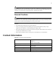
7 Specifications and Compliance Certifications This chapter details the Topspin 270 specifications and compliance certifications. Chassis and Management Interface Table 7-1: Chassis and Management General Specifications Operating Temperature Ranges 0 to 40C Operating Temperature 0 to 42C Non-Operating Temperature -40 to 70C Operating Temperature Gradient 20C max.
Table 7-1: Chassis and Management General Specifications Operating Temperature Ranges 0 to 40C Non-Operating Vibration, random 2.09Grms, 3-axis, bottom/top, left/right, front/back Max. Operating Inclination 15 degrees Electrical Specifications Table 7-2: Electrical Specifications Category Specification AC Input Auto-ranging 90-264VAC, 47-63Hz.
Product Markings • UL, FCC Statement, VCCI, CE, ICES
Index A active controller card 11 admin status 81 C card operational state 79 reset 80 card reset 80 chassis ID about 19 LEDs 74 chassis manager launching 32 LEDs 78 controller card identify active 11 upgrade 59 controllerFabric12x 79 core slot about 18 D diag card 90 diag chassis test standard 93 diag power-supply 97 F fabric controller LEDs general 70 master status 70 module status 70 fabric controller modules about 18 fabric12x 79 fail-over fabric controller 42 management interface module 18 management s
R rack-locator 89 reload 92 reset card 80 reset controller card 59 S safety information vii setup 32 show card 11 show diag chassis 93 show diag fru-error 96, 98 show diag post 94 show power-supply 97 slot numbers 15 speed port 81 starting Chassis Manager 32 switch configuration 32 switch fabric end-nodes about the fabric controller module 18 switch fabric spine about the fabric controller module 18 system controller about the fabric controller module 18 system-wide status LED 66 T temperature monitor with