
User Manual


4 300 Series Managed Switches
CAUTION For stability, load the rack from the bottom to the top, with the
heaviest devices on the bottom. A top-heavy rack is likely to
be unstable and may tip over.
Wall Mounting
Only the 8-port models of the switch can be wall-mounted.
NOTE The switch should be mounted so that the ports face up or down.
Do not mount the switch with the ports to the side.
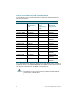
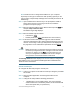
There is a wall-mount kit packed with your switch. The dimensions for the
mount kit are as follows:
Mount the managed switch to the wall by drilling two pilot holes
3.7 inches (95 mm) apart, attaching the provided anchors and screws to
the wall, then sliding the switch into position on the screws.
The switch should have a minimum of 5 inches (130 mm) of clearance on all
sides.
WARNING Insecure mounting may damage the device or cause injury.
Cisco is not responsible for damages incurred by insecure wall-
mounting.
1 8 mm/0.4 in 2 22.2 mm/0.9 in 3 6.8 mm/0.3 in 4 17.6 mm/0.7 in
1
2
4
3
196243