English C H A P T E R 1 Cisco 831 Router and Cisco SOHO 91 Router Cabling and Setup Quick Start Guide Quick Start Guide • Cisco One-Year Limited Hardware Warranty Terms • Easy Installation: Try These Steps First! (CRWS Users) • Overview • Parts List • Verify the PC Setup (CRWS Users) • Connect the Router to a PC • Connect the Router to an External Ethernet Switch (Optional) • Connect the Router to a DSL or a Cable Modem • Connect a Terminal or PC to the Console Port (Optional) • Connec
Chapter 1 Cisco 831 Router and Cisco SOHO 91 Router Cabling and Setup Quick Start Guide Cisco One-Year Limited Hardware Warranty Terms Cisco One-Year Limited Hardware Warranty Terms There are special terms applicable to your hardware warranty and various services that you can use during the warranty period. Your formal Warranty Statement, including the warranty applicable to Cisco software, is included on the CD that accompanies your Cisco product.
Chapter 1 Cisco 831 Router and Cisco SOHO 91 Router Cabling and Setup Quick Start Guide Easy Installation: Try These Steps First! (CRWS Users) To Receive a Return Materials Authorization (RMA) Number Contact the company from whom you purchased the product. If you purchased the product directly from Cisco, contact your Cisco Sales and Service Representative. Complete the information below, and keep it for reference.
Chapter 1 Cisco 831 Router and Cisco SOHO 91 Router Cabling and Setup Quick Start Guide Parts List These documents are available on the Cisco Documentation CD-ROM and on the World Wide Web. You can access the most current Cisco documentation on the World Wide Web at the following sites: Note • http://www.cisco.com • http://www-china.cisco.com • http://www-europe.cisco.
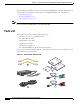
Chapter 1 Cisco 831 Router and Cisco SOHO 91 Router Cabling and Setup Quick Start Guide Verify the PC Setup (CRWS Users) Note 1 Two yellow Ethernet cables 4 Product documentation and Cisco 800 and SOHO Series CD-ROM 2 Desktop power adapter 5 Light blue console cable (RJ-45-to-DB-9) 3 Black power cord An optional cable used for connecting a Cisco 831 router’s console port to an async modem is available for dial backup and remote management. The SOHO 91 router does not need this cable.
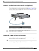
Chapter 1 Cisco 831 Router and Cisco SOHO 91 Router Cabling and Setup Quick Start Guide Connect the Router to a PC Figure 1-2 Connecting the Router to a PC 1 2 ETHERN ET 10BASET COMPUT ERS (E0) CONSOL E Cisco 831 ETHERN ET 10BASET 4 3 2 +18 VDC 1 INTERNE T (E1) ON OFF 3 4 82015 5 1 Cisco 831 router 4 PC 2 Yellow Ethernet cable 5 RJ-45 port on the network interface card (NIC) 3 Port 4 on the built-in Ethernet switch Cisco 831 and SOHO 91 Router Cabling and Setup Quick Star
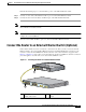
Chapter 1 Cisco 831 Router and Cisco SOHO 91 Router Cabling and Setup Quick Start Guide Connect the Router to an External Ethernet Switch (Optional) Perform the following steps to connect the PC to port 4 on the built-in Ethernet switch: Step 1 Connect one end of the yellow Ethernet cable to port 4 on the built-in Ethernet switch. Step 2 Connect the other end of the cable to the RJ-45 port on the NIC installed in the PC.
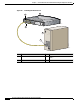
Chapter 1 Cisco 831 Router and Cisco SOHO 91 Router Cabling and Setup Quick Start Guide Connect the Router to a DSL or a Cable Modem Perform the following steps to connect the router to an external Ethernet switch: Step 1 Connect one end of the yellow cable to built-in Ethernet switch port 4 on the router. Step 2 Connect the other end of the cable to the available port on the external Ethernet switch to add additional Ethernet connections. Turn on the Ethernet switch if it is not already turned on.
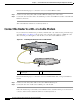
Chapter 1 Cisco 831 Router and Cisco SOHO 91 Router Cabling and Setup Quick Start Guide Connect a Terminal or PC to the Console Port (Optional) Connect a Terminal or PC to the Console Port (Optional) The console port is a service port to which you can connect a terminal or PC in order to configure the software by using the command-line interface (CLI) or to troubleshoot problems with the router. To connect a terminal or PC to the console port, follow the steps given after Figure 1-5.
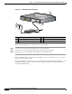
Chapter 1 Cisco 831 Router and Cisco SOHO 91 Router Cabling and Setup Quick Start Guide Connect the Power and Turn On the Router Figure 1-6 Connecting Power to the Router 82019 1 ETHERN ET 10BASET COMPUT ERS (E0) CONSOL E Cisco 831 ETHERN ET 10BASET 4 3 2 +18 VDC 1 INTERNE T (E1) ON OFF 2 5 3 4 1 Cisco 831 router 4 Desktop power adapter 2 Router input jack 5 Power cord plug 3 Power cord Perform the following steps to connect the router to the AC adapter: Step 1 Connect on
Chapter 1 Cisco 831 Router and Cisco SOHO 91 Router Cabling and Setup Quick Start Guide Check the PC Configuration (CRWS Users) Check the PC Configuration (CRWS Users) Only follow the instructions in this section if CRWS is installed on the router. If SDM is installed, refer to the “If SDM is Installed On the Router” section on page 1-14. Each PC that is connected to the router must be configured to use TCP/IP and to use DHCP automatically to obtain its IP address.
Chapter 1 Cisco 831 Router and Cisco SOHO 91 Router Cabling and Setup Quick Start Guide Start the CRWS Software (CRWS Users) If You Cannot Connect to a Website If you cannot connect to the Internet using the factory configuration, or if you have loaded new Cisco IOS software on the router since you installed it, you can configure the router by using the Cisco Router Web Setup (CRWS) software, or by using Security Device Manager (SDM) software, if you specified SDM be installed when you ordered the router
Chapter 1 Cisco 831 Router and Cisco SOHO 91 Router Cabling and Setup Quick Start Guide Start the CRWS Software (CRWS Users) Figure 1-7 CRWS Dashboard Page If the CRWS dashboard page does not appear when you enter the URL http://10.10.10.1, test the connection between the PC and the router by doing the following: • Check that the OK LED on the router is on, and check the cable connection between the router and the PC.
Chapter 1 Cisco 831 Router and Cisco SOHO 91 Router Cabling and Setup Quick Start Guide If SDM is Installed On the Router • If the web page still does not appear, verify that the PC is configured to automatically receive an IP address. Follow the instructions in Step 4 in the “Start the CRWS Software (CRWS Users)” section on page 1-12. If you need more information, refer to the Cisco Router Web Setup Troubleshooting Guide, which is available on the Cisco 800 and SOHO Series Product Documentation CD-ROM.
Chapter 1 Cisco 831 Router and Cisco SOHO 91 Router Cabling and Setup Quick Start Guide About the Product CD System Requirements The Cisco 800 and SOHO Series Product Documentation CD runs on systems that meet the requirements listed in Table 1. Table 1 System Requirements for Documentation CD Component Requirement Processor Pentium 150 MHz or faster recommended PC OS Microsoft Windows 95 Microsoft Windows 98 Microsoft Windows 2000 Microsoft Windows NT 4.
Chapter 1 Cisco 831 Router and Cisco SOHO 91 Router Cabling and Setup Quick Start Guide Obtaining Documentation Printing Documents To print a document: Step 1 Click the Printer icon on the Acrobat toolbar. The Windows Print Dialog box appears. Step 2 Select your default printer, and click OK. Obtaining Documentation These sections explain how to obtain documentation from Cisco Systems. World Wide Web You can access the most current Cisco documentation on the World Wide Web at this URL: http://www.
Chapter 1 Cisco 831 Router and Cisco SOHO 91 Router Cabling and Setup Quick Start Guide Obtaining Technical Assistance Documentation Feedback You can submit comments electronically on Cisco.com. In the Cisco Documentation home page, click the Fax or Email option in the “Leave Feedback” section at the bottom of the page. You can e-mail your comments to bug-doc@cisco.com.
Chapter 1 Cisco 831 Router and Cisco SOHO 91 Router Cabling and Setup Quick Start Guide Obtaining Technical Assistance Cisco TAC inquiries are categorized according to the urgency of the issue: • Priority level 4 (P4)—You need information or assistance concerning Cisco product capabilities, product installation, or basic product configuration. • Priority level 3 (P3)—Your network performance is degraded. Network functionality is noticeably impaired, but most business operations continue.