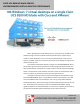
CISCO UCS B200 M3 BLADE SERVER: UNCOMPROMISED VIRTUAL DESKTOP PERFORMANCE u When deploying your virtual desktop solution, choosing server hardware that is powerful enough across the compute and memory dimensions to support a large number of virtual desktops is crucial. The more virtual desktops per server you can support, the fewer servers you need to buy to provide virtual desktops to support your desired number of users.
MORE VDI SESSIONS ARE BETTER Choosing the right combination of hardware and software for your virtual desktop solution can significantly impact your bottom line. A robust hypervisor, top-of-the-line virtual desktop software, and a server built with powerful processors and an expansive memory footprint all work together to ensure you can meet the needs of your employees without your spending money, space, and time on additional hardware.
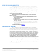
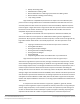
Response times for virtual desktops on a single Cisco UCS B200 M3 Blade Server 6,000 5,000 Login VSImax = 186 Dynamic VSImax = 4,223 Baseline = 978 Miiliseconds 4,000 3,000 2,000 1,000 0 5 29 54 75 96 120 Number of users Average Response 141 163 183 VSI Index Average Figure 1: Average virtual desktop response times at various numbers of virtual desktops on the Cisco UCS B200 M3 Blade Server.
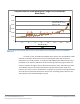
Average processor utilization 100 90 CPU percentage used 80 70 60 50 40 30 20 10 0 0:00 0:10 0:20 0:30 0:40 0:50 1:00 1:10 1:20 Elapsed time (hours:minutes) Figure 2: Processor utilization throughout the test. Figure 3 shows the memory usage throughout the test. The steep increase at the beginning of the chart reflects the beginning of the test with the 193 virtual desktops powering on. After boot up, vDTs that were not active conserved memory via page sharing.
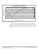
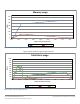
Memory usage 350 300 Gbytes 250 200 150 100 50 0 0:00 0:10 0:20 0:30 0:40 0:50 1:00 1:10 1:20 Elapsed time (hours:minutes) Memory in use Page sharing Figure 3: Memory usage throughout the test. Figure 4 shows the fabric usage throughout the test. Total fabric usage 1,000 900 800 Mbps 700 600 500 400 300 200 100 0 0:00 0:10 0:20 0:30 0:40 0:50 1:00 1:10 1:20 Elapsed time (hours:minutes) Storage (vHBA) Network Total Figure 4: Fabric usage throughout the test.
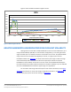
Figure 5 shows the IOPS recorded throughout the test. IOPS 8,000 7,000 6,000 5,000 4,000 3,000 2,000 1,000 0 0:00 0:10 0:20 0:30 0:40 0:50 1:00 1:10 1:20 Elapsed time (hours:minutes) Total OPS Read OPS Write OPS Figure 5: IOPS throughout the test.
WHAT WE TESTED About the Cisco UCS B200 M3 Blade Server The Cisco UCS B200 M3 Blade Server is an enterprise-class blade server powered by the new Intel Xeon processor E5-2600 series to deliver high performance and outstanding I/O throughput for your applications. Supporting up to 384 GB of RAM with 24 DIMM slots, the Cisco UCS M200 M3 has expansive memory capabilities to support your heavy workloads.
configure bandwidth settings (by user, use case, or network requirements), which can reduce bandwidth by up to 75 percent and improve protocol efficiency. To learn more about VMware View 5, visit http://www.vmware.com/products/view/overview.html. About VMware vSphere 5 vSphere 5 is the latest virtualization operating system from VMware. vSphere 5 allows companies to virtualize their server, storage, and networking resources, achieving a consolidation ratio greater than 15:1.
Bullzip: Generating a PDF Adobe Reader®: Reading a PDF Microsoft PowerPoint®: Watching a presentation and adding a slide Microsoft Excel®: Reading and minimizing 7-Zip: Saving a ZIP file Login VSI Version 3.0 (Release 6) benchmarks user experience more effectively than previous versions of Login VSI because its workloads and what the VSI Index measures more accurately reflect the tasks actual users perform on their virtual desktops. Reported response times are higher in Login VSI 3.
understand and quantify the specific needs of VDI users and create baseline settings to ensure the results are representative of your environment. For more details on the settings used in our testing, see Appendix B. For more information on Classic and Dynamic VSI max, see http://www.loginvsi.com/en/admin-guide/analyzing-results#h0-1-calculating-vsimax For more information on Login VSI 3.0, see http://www.loginconsultants.com/index.php?option=com_content&task=view&id=390.
APPENDIX A – SERVER AND STORAGE CONFIGURATION INFORMATION Figure 6 provides detailed configuration information about the test servers. Note that we used the Cisco UCS B200 M3 Blade Server for the systems under test and used the Cisco UCS B200 M2 Blade Server for our test bed infrastructure. Figure 7 details the storage we used in our tests.
System RAID controller Vendor and model Controller firmware Operating system Name Build number Language Operating system power profile I/O Adapters Cisco UCS B200 M3 server Cisco UCS B200 M2 server LSI MegaRAID SAS 2004 20.10.1-0061 LSI Logic® SAS 1064E 01.32.04.
APPENDIX B – HOW WE TESTED To determine the number of virtual desktops the server could support, we ran incremental tests increasing the virtual desktop load until Dynamic VSI Max was reached. The minimum number of sessions required to archive Dynamic VSI max was 193. When testing 193 virtual desktops, we recorded a Dynamic VSI max of 186. At 192 sessions, the benchmark did not achieve Dynamic VSI Max. At the end of the test, the processors on the Cisco UCS B200 M3 Blade Server were nearly saturated.
Figure 8: Our test environment.
Figure 9: Our logical network layout. Setting up the storage To host all testing infrastructure, we installed a Cisco UCS B200 M2 Blade Server. Using UCS Service profiles, we configured the local disks in a RAID 1 configuration to host the ESXi hypervisor. To host all virtual desktops, we installed a Cisco UCS B200 M3 Blade Server. Using UCS Service profiles, we configured the local disks in a RAID 1 configuration to host the ESXi hypervisor.
5. 6. 7. 8. 9. 10. 11. 12. 13. Select Enclosure 0, Disk 10 and 11, and click OK. Click StorageStorage ConfigurationStorage Pools. Click RAID Groups, and click Create. Create storge. In the General tab, select RAID 0. In the General tab, for disks, click Manual and select Disk enclosure 0, SSD disks 4, 5 and 6, and click Apply. Click Create. In the General tab, select RAID 5. In the General tab, for disks, click Manual, and select Disk enclosure 0: a. Disk enclosure 0: SSD disks 7, 8, 9 b.
8. On the Installation Complete screen, press Enter to reboot. Configuring ESXi after installation (network) 1. On the ESXi 5.0 screen, press F2, enter the root password, and press Enter. 2. On the System Customization screen, select Troubleshooting Options, and press Enter. 3. On the Troubleshooting Mode Options screen, select Enable ESXi Shell, and press Enter. 4. Select Enable SSH, press Enter, and press Esc. 5. On the System Customization screen, select Configure Management Network. 6.
3. 4. 5. 6. 7. On the Troubleshooting Mode Options screen, select Enable ESXi Shell, and press Enter. Select Enable SSH, press Enter, and press Esc. On the System Customization screen, select Configure Management Network. On the Configure Management Network screen, select IP Configuration. On the IP Configuration screen, select Set static IP; enter an IP address, subnet mask, and default gateway; and press Enter. 8. On the Configure Management Network screen, press Esc.
Creating the ESXi datastore (LUN1-4) 1. 2. 3. 4. 5. 6. 7. 8. 9. Log into infra as root with the vSphere client. Click Configuration tabStorageAdd Storage. Select LUN1, and click Next. Select VMFS-5, and click Next. Review the disk layout, and click Next. For Datastore name, type LUN1 and click Next. For Capacity, select Maximum Available Space, and click Next. Click Finish to create the datastore. Repeat steps 1 through 8 to create LUN2, 3 and 4.
Installing the Microsoft Windows Server 2008 R2 operating system on the VM 1. Choose the language, time and currency, and keyboard input. Click Next. 2. Click Install Now. 3. Choose Windows Server 2008 R2 Enterprise (Full Installation), and click Next. 4. Accept the license terms, and click Next. 5. Click Custom. 6. Click the Disk, and click Drive options (advanced). 7. Click NewApplyFormat, and click Next. 8. After the installation completes, click OK to set the Administrator password. 9.
Configuring the Windows time service on DC1 To ensure reliable time, we pointed our Active Directory server to a physical NTP server. 1. Open a command prompt. 2. Type the following: w32tm /config /syncfromflags:manual /manualpeerlist:"" W32tm /config /reliable:yes W32tm /config /update W32tm /resync Net stop w32time Net start w32time Setting up DHCP services on DC1 1. 2. 3. 4. 5. 6. Click StartAdministrative ToolsServer ManagerAdd Roles. Select DHCP Server, and click Next.
6. In the GPO, browse to Computer ConfigurationAdministrative TemplateClassic Administrative Template (ADM)PCoIP Session Variables Not Overridable Administrative settings, and click Turn off Build-to-lossless feature. Right-click, and click Edit. 7. Select the radio button for Enabled, and tick the box next to I accept to turn off the Build-to-lossless feature. 8.
17. Make the OS virtual disk size 40 GB, choose thick-provisioned lazy zeroed, specify the OS datastore on the data1, and click Next. 18. Keep the default virtual device node (0:0), and click Next. 19. Connect the VM virtual CD-ROM to the Microsoft Windows Server 2008 R2 installation disk. 20. Click Finish. 21. Right-click the vCenter VM, and click Edit settings. 22. Click the Resources tab, click Memory, check the Reserve all guest memory box, and click OK. 23. Start the VM.
15. Click Install to finish the vCenter Server installation. 16. When the installation completes, restart the server. 17. Using the vSphere client, log into vCenter5 as view5\administrator 18. Right-click the root of vCenter5, and click New Data center. 19. Name the New datacenter datacenter 20. Add the server named infra.view5.com to the datacenter. 21. Add the server named SUT.view5.com to the datacenter. Configuring VMware Composer SQL ODBC 1.
13. Leave the default virtual storage controller, and click Next. 14. Choose to create a new virtual disk, and click Next. 15. Make the OS virtual disk size 40 GB, choose thick-provisioned lazy zeroed, specify the OS datastore on the external storage, and click Next. 16. Keep the default virtual device node (0:0), and click Next. 17. Connect the VM virtual CD-ROM to the Microsoft Windows Server 2008 R2 installation disk. 18. Right-click the View5 VM, and click Edit settings. 19.
Setting up a Windows 7 Enterprise x86 image for VMware View 5 linked clone “gold image” and a Windows 7 Enterprise x64 image VSI Launchers Using the vSphere client, we created a Windows 7 Enterprise x64 VM with the Login VSI launcher software, and cloned it to create six Login VSI launchers. We also created a single optimized Windows 7 Enterprise x86 VM on the SUT as the gold image for View 5 linked clone deployment. Installing the Windows 7 Enterprise (x64) Login VSI launcher 1.
Adjusting page file on the launcher 1. Log in as view5/administrator 2. Right-click ComputerPropertiesChange settingsAdvancedPerformanceSettings. 3. In Performance settings, select the Advanced tab, and select Change for Virtual Memory. 4. Deselect Automatically manage page file. 5. Select Custom size, type 2048 for both values, and select Set. Disabling Windows Firewall The domain GPO automatically disables the Windows Firewall. Installing Microsoft Office 2007 Professional on the launcher 1.
9. 10. 11. 12. 13. 14. 15. 16. 17. 18. 19. 20. 21. 22. 23. 24. 25. 26. 27. 28. 29. 30. 31. 32. 33. 34. 35. 36. Choose Windows, choose Microsoft Windows 7 (32-bit), and click Next. Choose one virtual processor, and click Next. Choose 1536 GB RAM, and click Next. Click 1 for the number of NICs, select E1000 VDI-NET, and click Next. Leave the default virtual storage controller, and click Next. Choose to create a new virtual disk, and click Next.
Installing the VMware View agent on gold_image 1. Log into the gold_image. 2. Browse to the VMware View agent media. 3. At the Welcome screen and License agreement, accept the terms, and click Next. 4. Accept install defaults, and click Next. 5. Select Do not enable the remote desktop capability on this computer, and click Next. 6. Keep the default install directory, and click Install. 7.
15. Highlight the pool named Pool, and click Entitlements. 16. Click Add, select login_VSI/view5.com, and click OK. 17. Ensure all 193 desktops have a status of ready. Running the Login VSI benchmark We used six launchers configured in parallel to run a medium workload of 193 user sessions on the VMware View 5 pool. For more information on how to run a Login VSI test, see: http://www.loginvsi.com/en/adminguide/performing-tests.
APPENDIX C - LOGIN VSI INI FILES USED FOR TESTING VMware View 5 launcher.ini [Launcher] Servername= Username= Password= Domain= ConnectionType="Custom with CSV file" ConnectionNumber=User CCL=c:\program files\VMware\VMWare View\Client\bin\wswc.exe -serverURL http://VIEW5 -username %CSV_User% -password Password1 -domainname View5 desktopname pool -Standalone -logInAsCurrentUser False -connectUSBOnStartup False CSV=\\DC1\Share\csv\view5-user.
APPENDIX D – RESOURCE UTILIZATION DETAILS Figure 10 shows that the server supporting the virtual desktop load never exceeded 3 percent of the bandwidth available, leaving over 97 percent of fabric available for future scaling. Figure 10: Bandwidth usage for test. In our testing, the aggregate workload never exceeded 3 percent of available compute fabric bandwidth.
ABOUT PRINCIPLED TECHNOLOGIES Principled Technologies, Inc. 1007 Slater Road, Suite 300 Durham, NC, 27703 www.principledtechnologies.com We provide industry-leading technology assessment and fact-based marketing services. We bring to every assignment extensive experience with and expertise in all aspects of technology testing and analysis, from researching new technologies, to developing new methodologies, to testing with existing and new tools.