Spec Sheet Cisco UCS B200 M3 Blade Server CISCO SYSTEMS 170 WEST TASMAN DR. SAN JOSE, CA, 95134 WWW.CISCO.COM PUBLICATION HISTORY REV C.
OVERVIEW . . . . . . . . . . . . . . . . . . . . . . . . . . . . . . . . . . . . . . . . . . . . . . . 3 DETAILED VIEWS . . . . . . . . . . . . . . . . . . . . . . . . . . . . . . . . . . . . . . . . . . . 4 Blade Server Front View . . . . . . . . . . . . . . . . . . . . . . . . . . . . . . . . . . . . . . . . . . . . . . .4 BASE SERVER STANDARD CAPABILITIES and FEATURES . . . . . . . . . . . . . . . . . 5 CONFIGURING the SERVER . . . . . . . . . . . . . . . . . . . . . . . . . . . . . . . . . . . .
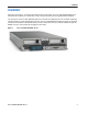
OVERVIEW OVERVIEW Delivering performance, versatility and density without compromise, the Cisco UCS B200 M3 Blade Server addresses the broadest set of workloads, from IT and web infrastructure through distributed database. The enterprise-class Cisco UCS B200 M3 blade server extends the capabilities of Cisco’s Unified Computing System portfolio in a half-width blade form factor.
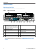
DETAILED VIEWS DETAILED VIEWS Blade Server Front View Figure 2 is a detailed front view of the Cisco UCS B200 M3 Blade Server.
BASE SERVER STANDARD CAPABILITIES and FEATURES BASE SERVER STANDARD CAPABILITIES and FEATURES Table 1 lists the capabilities and features of the base server. Details about how to configure the server for a particular feature or capability (for example, number of processors, disk drives, or amount of memory) are provided in CONFIGURING the SERVER on page 7. NOTE: NOTE: The B200 M3 blade server requires UCS Manager (UCSM) to operate as part of the UCS system. ■ The B200 M3 with E5-2600 CPUs requires UCSM 2.
BASE SERVER STANDARD CAPABILITIES and FEATURES Table 1 Capabilities and Features (continued) Capability/Feature Video Description The Cisco Integrated Management Controller (CIMC) provides video: ■ Matrox G200e video controller ■ Integrated 2D graphics core with hardware acceleration ■ Interfaces Supports all display resolutions up to 1920 x 1200 x 16 bpp resolution at 60 Hz ■ 24-bit color depth for all resolutions less than 1600x1200 ■ Up to 256 MB video memory ■ Front panel • One console con
CONFIGURING the SERVER CONFIGURING the SERVER Follow these steps to configure the Cisco UCS B200 M3 Blade Server: ■ STEP 1 VERIFY SERVER SKU, page 8 ■ STEP 2 CHOOSE CPU(S), page 9 ■ STEP 3 CHOOSE MEMORY, page 12 ■ STEP 4 CHOOSE HARD DISK DRIVES or SOLID STATE DRIVES (OPTIONAL), page 18 ■ STEP 5 CHOOSE ADAPTERS, page 20 ■ STEP 6 ORDER A TRUSTED PLATFORM MODULE, page 24 ■ STEP 7 ORDER CISCO FLEXIBLE FLASH SECURE DIGITAL CARDS, page 25 ■ STEP 8 ORDER OPTIONAL INTERNAL USB 2.
CONFIGURING the SERVER STEP 1 VERIFY SERVER SKU Verify the product ID (PID) of the server as shown in Table 2. Table 2 PID of the Base UCS B200 M3 Blade Server Product ID (PID) Description UCSB-B200-M3 UCS B200 M3 Blade Server w/o CPU, memory, HDD, VIC 1340 or 1240 adapter, or mezzanine adapters The base Cisco UCS B200 M3 blade server does not include the following components.
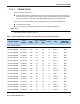
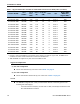
CONFIGURING the SERVER STEP 2 CHOOSE CPU(S) The standard CPU features are: ■ Intel Xeon E5-2600 v2 and E5-2600 series processor family CPUs. See the following link for instructions on how to upgrade your server from Intel Xeon E5-2600 to Intel Xeon E5-2600 v2 CPUs as well as how to upgrade to 1866-MHz DIMMs (supported on E5-2600 v2 CPUs): http://www.cisco.com/en/US/docs/unified_computing/ucs/hw/CPU/IVB/install/IVB-B.
CONFIGURING the SERVER Table 3 Supported Intel CPUs: E5-2600 v2 and E5-2600 Series Processor Family CPUs (continued) QPI Highest DDR3 DIMM Clock Support (MHz)1 8 8 GT/s 1600 20 8 8 GT/s 1600 115 20 8 8 GT/s 1600 2.90 130 15 6 8 GT/s 1600 E5-2665 2.40 115 20 8 8 GT/s 1600 UCS-CPU-E5-2660 E5-2660 2.20 95 20 8 8 GT/s 1600 UCS-CPU-E5-2658 E5-2658 2.10 95 20 8 8 GT/s 1600 UCS-CPU-E5-2650 E5-2650 2.00 95 20 8 8 GT/s 1600 UCS-CPU-E5-2650L E5-2650L 1.
CONFIGURING the SERVER — The connectivity options are: • VIC 1340 or 1240 installed in VIC 1340/1240 slot and no adapter installed in the mezzanine slot • VIC 1340 or 1240 installed in VIC 1340/1240 slot and a Port Expander Card installed in the mezzanine slot. ■ See NEBS Compliance on page 49 for complete information on network connectivity support for a B200 M3 configured with 1 CPU or 2 CPUs. ■ For optimal performance, select DIMMs with the highest clock speed for a given processor.
CONFIGURING the SERVER STEP 3 CHOOSE MEMORY The standard memory features are: ■ Figure 3 12 DIMMs — Clock speed: 1866, 1600, or 1333 MHz — Ranks per DIMM: 1, 2, or 4 — Operational voltage: 1.35 or 1.5 V — Registered ■ DDR3 ECC registered DIMMs (RDIMMs) or load-reduced DIMMS (LRDIMMS) ■ Memory is organized with four memory channels per CPU, with up to three DIMMs per channel (DPC), as shown in Figure 3. Maximum memory capacity is 768 GB (B200 M3 configured with 2 CPUs with 32 GB DIMMs).
CONFIGURING the SERVER Choose DIMMs and Memory Mirroring Select the memory configuration and whether or not you want the memory mirroring option. The supported memory DIMMs and the mirroring option are listed in Table 4. NOTE: When memory mirroring is enabled, the memory subsystem simultaneously writes identical data to two adjacent channels.
CONFIGURING the SERVER Supported Configurations (1) B200 M3 configured with 1 CPU without memory mirroring ■ Select from 1 to 12 DIMMs for CPU 1 (note that there are 12 DIMM slots available) (2) B200 M3 configured with 1 CPU with memory mirroring ■ Select 2, 4, 6, 8, or 12 DIMMs for CPU 1.
CONFIGURING the SERVER (3) B200 M3 configured with 2 CPUs without memory mirroring: ■ Select from 1 to 12 DIMMs per CPU (note that there are 12 DIMM slots per CPU) (4) B200 M3 configured with 2 CPUs with memory mirroring: ■ Select 2, 4, 6, 8, or 12 DIMMs per CPU.
CONFIGURING the SERVER Caveats ■ System speed is dependent on how many DIMMs are populated per channel. See Table 7 for details. Table 7 DIMM Memory Speeds 1333-MHz Capable CPU DIMM Speed 1333 DIMM 1600 DIMM 1866 DIMM4 1600-MHz Capable CPU 1866-MHz Capable CPU LRDIMM RDIMM (DR, SR) LRDIMM RDIMM (DR, SR) LRDIMM RDIMM (DR, SR) Voltages Voltages Voltages Voltages Voltages Voltages DPC 1.3 V 1.5 V 1.3 V 1.5 V 1.3 V 1.5 V 1.
CONFIGURING the SERVER — DIMM choice — DIMM population (how many DIMMs per channel are populated) — BIOS setting. For the DIMMs to run in power-savings mode (1.35 V, if the DIMM supports this), change the BIOS setting to power-savings mode. ■ With 3 RDIMMs populated per channel, memory always runs at 1.5 V regardless if the BIOS setting is power-savings mode (1.35 V) or performance mode (1.5 V). ■ With 3 LRDIMMs populated per channel, memory can operate at 1.5 V or 1.
CONFIGURING the SERVER STEP 4 CHOOSE HARD DISK DRIVES or SOLID STATE DRIVES (OPTIONAL) The UCS B200 M3 can be ordered with or without drives. The standard disk drive features are: ■ 2.5-inch small form factor ■ Hot-pluggable ■ Sled-mounted NOTE: The UCS B200 M3 blade server meets the external storage target and switch certifications as described in the following link: http://www.cisco.com/en/US/docs/switches/datacenter/mds9000/interoperabilit y/matrix/Matrix8.
CONFIGURING the SERVER NOTE: The integrated RAID controller supports hard disk drives (HDDs) or solid state drives (SSDs). Write cache is not implemented. SSDs are recommended for applications requiring high-speed local storage, which is an order of magnitude faster than HDDs. Supported Configurations (1) 1-Drive System ■ Select one of the drives listed in Table 8. (1) 2-Drive System ■ Select two identical drives from Table 8. There is no support for mixing of drive types or capacities.
CONFIGURING the SERVER STEP 5 CHOOSE ADAPTERS The adapter offerings are: ■ Cisco Virtual Interface Cards (VICs) Cisco developed Virtual Interface Cards (VICs) to provide flexibility to create multiple NIC and HBA devices. The VICs also support adapter Fabric Extender and Virtual Machine Fabric Extender technologies. ■ Converged Network Adapters (CNAs) Emulex and QLogic Converged Network Adapters (CNAs) consolidate Ethernet and Storage (FC) traffic on the Unified Fabric by supporting FCoE.
CONFIGURING the SERVER Table 9 Supported Mezzanine Adapters (continued) Product ID (PID) PID Description Connector UCS-VIC-M82-8P Cisco UCS VIC 1280 dual 40Gb capable Virtual Interface Card Mezzanine Converged Network Adapters (CNAs) UCSB-MEZ-QLG-03 Cisco UCS CNA M73KR-Q QLogic Adapter Mezzanine UCSB-MEZ-ELX-03 Cisco UCS CNA M73KR-E Emulex Adapter Mezzanine Cisco Storage Accelerators UCSB-F-FIO-785M Cisco UCS 785 GB MLC Fusion-io ioDrive2 Mezzanine UCSB-F-FIO-365M Cisco UCS 365 GB MLC Fusio
CONFIGURING the SERVER Table 10 Supported VIC 1340/1240 and Mezzanine Adapter Configurations Fabric Extender Compatibility Adapter in VIC 1340/1240 Slot Adapter in Mezzanine Slot Ports Reference None 2 x 10 Gb Figure 14 on page 57 2104XP (PID N20-I6584) 2104XP VIC 1340 or 1240 (2) B200 M3 configured with 2 CPUs For a B200 M3 configured with 2 CPUs, the supported configurations are listed in Table 11. Choose one configuration.
CONFIGURING the SERVER Table 11 Supported VIC 1340/1240 and Mezzanine Adapter Configurations Fabric Extender Compatibility Adapter in VIC 1340/1240 Slot Adapter in Mezzanine Slot Ports Reference 2104XP (PID N20-I6584) 2104XP VIC 1340 or 1240 None 2 x 10 Gb Figure 25 on page 64 2104XP VIC 1340 or 1240 Cisco UCS Storage Accelerator 2 x 10 Gb Figure 26 on page 65 Notes... 1. Do not mix VIC 1240 with VIC 1380, and do not mix VIC 1340 with VIC 1280. 2.
CONFIGURING the SERVER STEP 6 ORDER A TRUSTED PLATFORM MODULE Trusted Platform Module (TPM) is a computer chip (microcontroller) that can securely store artifacts used to authenticate the platform (server). These artifacts can include passwords, certificates, or encryption keys. A TPM can also be used to store platform measurements that help ensure that the platform remains trustworthy.
CONFIGURING the SERVER STEP 7 ORDER CISCO FLEXIBLE FLASH SECURE DIGITAL CARDS Dual SDHC flash card sockets are provided on the front left side of the server. NOTE: Dual card support (mirroring) is supported with UCS Manager 2.2.x and later. The SDHC card ordering information is listed in Table 13.
CONFIGURING the SERVER STEP 8 ORDER OPTIONAL INTERNAL USB 2.0 DRIVE You may order one optional internal USB 2.0 drive. The USB drive ordering information is listed in Table 14. Table 14 USB 2.0 Drive Product ID (PID) PID Description UCS-USBFLSH-S-4GB 4GB Flash USB Drive (shorter) for all M3 servers NOTE: A clearance of 0.950 inches (24.1 mm) is required for the USB device to be inserted and removed (see the following figure). See Figure 5 on page 37 for the location of the USB connector.
CONFIGURING the SERVER STEP 9 CHOOSE OPERATING SYSTEM AND VALUE-ADDED SOFTWARE Several operating systems and value-added software programs are available. Select as desired from Table 15.
CONFIGURING the SERVER Table 15 OSs and Value-Added Software (for 2-CPU servers) (continued) PID Description Product ID (PID) Red Hat Enterprise Linux RHEL-2S-1G-1A RHEL/2 Socket/1 Guest/1Yr Svcs Required RHEL-2S-1G-3A RHEL/2 Socket/1 Guest/3Yr Svcs Required RHEL-2S-4G-1A RHEL/2 Socket/4 Guest/1Yr Svcs Required RHEL-2S-4G-3A RHEL/2 Socket/4 Guest/3Yr Svcs Required RHEL-2S-UG-1A RHEL/2 Socket/U Guest/1Yr Svcs Required RHEL-2S-UG-3A RHEL/2 Socket/U Guest/3Yr Svcs Required RHEL-HA-2S-1A RHEL Op
CONFIGURING the SERVER Table 15 OSs and Value-Added Software (for 2-CPU servers) (continued) PID Description Product ID (PID) VMware 5 VMW-VS5-STD-1A VMware vSphere 5 Standard for 1 Processor, 1 Year, Support Rqd VMW-VS5-STD-2A VMware vSphere 5 Standard for 1 Processor, 2 Year, Support Rqd VMW-VS5-STD-3A VMware vSphere 5 Standard for 1 Processor, 3 Year, Support Rqd VMW-VS5-STD-4A VMware vSphere 5 Standard for 1 Processor, 4 Year, Support Rqd VMW-VS5-STD-5A VMware vSphere 5 Standard for 1 Proces
CONFIGURING the SERVER STEP 10 CHOOSE OPERATING SYSTEM MEDIA KIT Choose the optional operating system media listed in Table 16.
CONFIGURING the SERVER STEP 11 CHOOSE SERVICE and SUPPORT LEVEL A variety of service options are available, as described in this section. Unified Computing Warranty, No Contract If you have noncritical implementations and choose to have no service contract, the following coverage is supplied: ■ Three-year parts coverage. ■ Next business day (NBD) parts replacement eight hours a day, five days a week. ■ 90-day software warranty on media. ■ Downloads of BIOS, drivers, and firmware updates.
CONFIGURING the SERVER Unified Computing Warranty Plus Service For faster parts replacement than is provided with the standard Cisco Unified Computing System warranty, Cisco offers the Cisco Unified Computing Warranty Plus Service. You can choose from several levels of advanced parts replacement coverage, including onsite parts replacement in as little as four hours.
CONFIGURING the SERVER Partner Support Service for UCS provides hardware and software support, including triage support for third party software, backed by Cisco technical resources and level three support. See Table 19.
CONFIGURING the SERVER You can choose a service listed in Table 21.
CONFIGURING the SERVER Table 22 Drive Retention Service Options Service Description UCS Support Service With Drive Retention UCS Warranty Plus With Drive Retention Service Program Name Service Level GSP UC SUPP DR UC PLUS DR Service Level Product ID (PID) UCSD5 8x5xNBD Onsite CON-UCSD5-B200M3 UCSD7 24x7x4 Onsite CON-UCSD7-B200M3 UCWD5 8x5xNBD Onsite CON-UCWD5-B200M3 UCWD7 24x7x4 Onsite CON-UCWD7-B200M3 For more service and support information, see the following URL: http://www.cisco.
CONFIGURING the SERVER ORDER OPTIONAL KVM LOCAL I/O CABLE* The KVM local I/O cable ships with every UCS 5100 Series blade server chassis accessory kit. The KVM local I/O cable provides a connection into the server, providing a DB9 serial connector, a VGA connector for a monitor, and dual USB ports for a keyboard and mouse. With this cable, you can create a direct connection to the operating system and the BIOS running on the server. The KVM local I/O cable ordering information is listed in Table 23.
SUPPLEMENTAL MATERIAL SUPPLEMENTAL MATERIAL System Board A top view of the UCS B200 M3 system board is shown in Figure 5.
SUPPLEMENTAL MATERIAL CPUs and DIMMs Physical Layout Memory is organized as shown in Figure 6.
SUPPLEMENTAL MATERIAL — Bank 1 - E1, F1, G1, and H1 (black DIMM slots) — Bank 2 - E2, F2, G2, and H2 (white DIMM slots) The DIMM and CPU physical layout is shown in Figure 7. The 12 DIMM slots at the left are controlled by CPU 1 and the 12 DIMM slots on the right are controlled by CPU 2.
SUPPLEMENTAL MATERIAL DIMM Population Rules When considering the memory configuration of your server, you should take into account the following: ■ For optimum performance, populate at least one DIMM per memory channel per CPU. ■ Do not mix RDIMMs with LRDIMMs. ■ Each channel has three DIMM slots (for example, channel A = slots A0, A1, and A2). ■ ■ — A channel can operate with one, two, or three DIMMs installed. — If a channel has only one DIMM, populate slot 0 first (the blue slot).
SUPPLEMENTAL MATERIAL DIMM Population Order Populate the DIMMs for a CPU according to Table 25.
SUPPLEMENTAL MATERIAL Recommended Memory Configuration This section explains the recommended DIMM population order rules for the B200 M3 server. ■ All DIMMs must be DDR3 DIMMs. ■ Do not mix: — DIMMs with different clock rates in a channel — RDIMMs and LRDIMMs — ECC and non-ECC DIMMs ■ There are blue, black, and white DIMM slots. Populate the blue slots first.
SUPPLEMENTAL MATERIAL Table 26 Recommended Memory Configurations for Intel Xeon E5-2600 v2 CPUs (with 1866- and 1600-MHz DIMMs)1 CPU 1 DIMMs Total System Memory Size CPU 2 DIMMs Blue Slots Bank 0 (A0,B0, C0,D0) Black Slots Bank 1 (A1,B1, C1,D1) White Slots Bank 2 (A2,B2, C2,D2) Blue Slots Bank 0 (E0,F0, G0,H0) Black Slots Bank 1 (E1,F1, G1,H1) White Slots Bank 2 (E2,F2, G2,H2) 4x8 GB 4x8 GB 4x8 GB 4x8 GB 4x8 GB 4x16 GB 2x16 GB — 4x16 GB 4x16 GB 4x8 GB — 4x16 GB 4x16 GB 4x32 GB 384 GB
SUPPLEMENTAL MATERIAL Table 27 Recommended Memory Configurations for Intel Xeon E5-2600 CPUs ( with 1600-MHz DIMMs).
SUPPLEMENTAL MATERIAL Additional DIMM Populations The list in Table 28 is not a complete list of all supported DIMM populations, but highlights common configuration options.
SUPPLEMENTAL MATERIAL Upgrade and Servicing-Related Parts This section lists the upgrade and servicing-related parts you may need during the life of your server. Some of these parts are configured with every server or with every UCS 5108 blade server chassis, and some may be ordered when needed or may be ordered and kept on hand as spares for future use. See Table 29. Table 29 Upgrade and Servicing-related Parts for UCS B200 M3 Server Spare Product ID (PID) Description N20-BBLKD= 2.
SUPPLEMENTAL MATERIAL Adding an Additional CPU (with CPU heat sink) All Cisco UCS two CPU socket-capable servers can be upgraded from having one to having two CPUs configured. You will need to order and install a heat sink when adding any additional CPU to a server. Instructions for installing the new CPU and heat sink can be found at the following link: http://www.cisco.com/en/US/docs/unified_computing/ucs/hw/chassis/install/B200M3.
SUPPLEMENTAL MATERIAL NOTE: When you purchase a spare CPU, the thermal grease with syringe applicator is included. Air Baffle Replacement Kit Air baffles are designed to direct airflow through the server to maintain server temperature at a safe operating level. The UCS B200 M3 server comes shipped with two identical air baffles covering the DIMM socket areas of the server. These baffles must always remain installed during server operation.
SUPPLEMENTAL MATERIAL NEBS Compliance When configured with the specific set of components shown in Table 30, the UCS B200 M3 blade server meets Network Building Equipment Standards (NEBS) Level 1 and Level 3 compliance. Table 30 B200 M3 NEBS Compliant Components Component Category CPUs DIMMs Description Product ID (PID) Up to two CPUs: Intel Xeon E5-2658v 2 .40 GHz 95W 10C/25MB Cache UCS-CPU-E52658B Up to two CPUs: Intel Xeon E5-2658 2.
SUPPLEMENTAL MATERIAL Network Connectivity This section explains how the UCS B200 M3 server connects to Fabric Interconnects using the network adapters in the UCS B200 M3 blade server and the Fabric Extender modules in the UCS 5108 blade server chassis. The UCS B200 M3 server plugs into the front of the UCS 5108 blade server chassis. The Fabric Extender modules plug into the back of the UCS 5108 series blade server chassis. A midplane connects the UCS B200 M3 blade server to the Fabric Extenders.
SUPPLEMENTAL MATERIAL The network adapter options are: ■ Cisco VIC 1340 or adapter. This adapter plugs into the VIC 1340/1240 slot and is natively capable of 4x10Gb ports and 256 PCIe devices. The capabilities of the adapter can easily be expanded by using the Port Expander Card in the mezzanine slot. ■ Cisco VIC 1380 or 1280 Mezzanine adapter.
SUPPLEMENTAL MATERIAL Figure 9 VIC 1340/1240 Port Connectivity The number of ports available at the mezzanine adapter depends on the type of mezzanine adapter that is plugged into the mezzanine slot on the system board. The maximum number of ports is four. The VIC 1340 or 1240 senses the type of adapter plugged into the mezzanine slot. In the event a Port Expander Card occupies the mezzanine slot, the four 10G KR ports between the adapters are used for port expansion; otherwise, they are unused.
SUPPLEMENTAL MATERIAL ■ ■ Emulex or QLogic I/O adapters — Emulex M73KR-E — QLogic M73KR-Q Cisco Storage Accelerator adapters — Cisco UCS 785 GB MLC Fusion-io ioDrive2 — LSI 400 GB SLC WarpDrive The following sections explain the various I/O options that are possible with the different Fabric Extenders (Cisco UCS 2208XP, 2204XP, and 2104XP) and the VIC 1340 or 1240 and mezzanine adapters.
SUPPLEMENTAL MATERIAL Figure 10 54 Option 1 - VIC 1340/1240 to UCS 2208XP Fabric Extender (no mezzanine adapter) Cisco UCS B200 M3 Blade Server
SUPPLEMENTAL MATERIAL In Figure 11, two ports from the VIC 1340/1240 are channeled to 2208XP Fabric Extender A and two are channeled to 2208XP Fabric Extender B. The Port Expander Card installed in the mezzanine slot acts as a pass-through device to channel two ports to each of the Fabric Extenders. The result is 40 Gbps of bandwidth to each Fabric Extender.
SUPPLEMENTAL MATERIAL Figure 12 Option 1 - VIC 1340/1240 to UCS 2204XP Fabric Extender (no mezzanine adapter) In Figure 13, one port from the VIC 1340/1240 is channeled to 2204XP Fabric Extender A and one is channeled to 2204XP Fabric Extender B. The Port Expander Card installed in the mezzanine slot acts as a pass-through device to channel one port to each of the Fabric Extenders. The result is 20 Gbps of bandwidth to each Fabric Extender.
SUPPLEMENTAL MATERIAL Connectivity using the Cisco UCS 2104XP Fabric Extender The option shown in Figure 14 demonstrates how the UCS B200 M3 blade serves connects to a UCS 2104XP Fabric Extender. In Figure 14, one port from the VIC 1340/1240 is channeled to 2104XP Fabric Extender A and one is channeled to 2104XP Fabric Extender B. The result is 10 Gbps of bandwidth to each Fabric Extender.
SUPPLEMENTAL MATERIAL B200 M3 Configured with 2 CPUs Connectivity using the Cisco UCS 2208XP Fabric Extender The Cisco UCS 2208XP is the second-generation Fabric Extender, and shares the same form factor as the current UCS 2100 series. The 2208XP is backwards compatible with the UCS 5108 Blade serve chassis.
SUPPLEMENTAL MATERIAL In Figure 16, two ports from the VIC 1340/1240 are channeled to 2208XP Fabric Extender A and two are channeled to 2208XP Fabric Extender B. The VIC 1380/1280 installed in the mezzanine slot also channels two ports to each of the Fabric Extenders. The result is 40 Gbps of bandwidth to each Fabric Extender.
SUPPLEMENTAL MATERIAL In Figure 18, two ports from the VIC 1340/1240are channeled to 2208XP Fabric Extender A and two are channeled to 2208XP Fabric Extender B. The Port Expander Card installed in the mezzanine slot acts as a pass-through device to channel two ports to each of the Fabric Extenders. The result is 40 Gbps of bandwidth to each Fabric Extender. Figure 18 Option 4 - VIC 1340/1240 and Port Expander Card to UCS 2208XP Fabric Extender In Figure 19, there is no VIC 1340/1240 adapter installed.
SUPPLEMENTAL MATERIAL Connectivity using the Cisco UCS 2204XP Fabric Extender The Cisco UCS 2204XP is a second-generation Fabric Extender, and shares the same form factor as the current UCS 2100 series. The 2204XP is backwards compatible with the UCS 5108 Blade serve chassis.
SUPPLEMENTAL MATERIAL In Figure 21, one port from the VIC 1340/1240 is channeled to 2204XP Fabric Extender A and one is channeled to 2204XP Fabric Extender B. The VIC 1380/1280 installed in the mezzanine slot also channels one port to each of the Fabric Extenders. The result is 20 Gbps of bandwidth to each Fabric Extender.
SUPPLEMENTAL MATERIAL In Figure 23, one port from the VIC 1340/1240 is channeled to 2204XP Fabric Extender A and one is channeled to 2204XP Fabric Extender B. The Port Expander Card installed in the mezzanine slot acts as a pass-through device to channel one port to each of the Fabric Extenders. The result is 20 Gbps of bandwidth to each Fabric Extender. Figure 23 Option 4 - VIC 1340/1240 and Port Expander Card to UCS 2204XP Fabric Extender In Figure 24, there is no VIC 1340/1240 adapter installed.
SUPPLEMENTAL MATERIAL Connectivity using the Cisco UCS 2104XP Fabric Extender The options shown in Figure 25 and Figure 26 demonstrate how the UCS B200 M3 blade server connects to a UCS 2104XP Fabric Extender. With this option, the mezzanine connector can either be empty or contain an independent Cisco Storage Accelerator adapter that communicates with CPU 2 through the PCIe bus.
SUPPLEMENTAL MATERIAL Figure 26 Option 2 - VIC 1340/1240 to UCS 2104XP Fabric Extender (Cisco Storage Accelerator installed) Cisco UCS B200 M3 Blade Server 65
TECHNICAL SPECIFICATIONS TECHNICAL SPECIFICATIONS Dimensions and Weight Table 31 UCS B200 M3 Dimensions and Weight Parameter Value Height 1.95 in. (50 mm) Width 8.00 in.(203 mm) Depth 24.4 in. (620 mm) Weight ■ Base server weight (no CPUs, no HDDs, no mezzanine adapters or memory) = 9.62 lbs (4.36 kg) ■ Minimally configured server (1 HDD, 2 CPUs, a VIC 1340/1240 but no mezzanine adapter) = 12.50 lbs (5.
TECHNICAL SPECIFICATIONS Cisco UCS B200 M3 Blade Server 67