
Specifications

Cisco UCS B200 M3 Blade Server
4
DETAILED VIEWS
DETAILED VIEWS
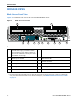
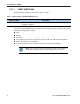
Blade Server Front View
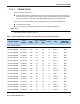
Figure 2 is a detailed front view of the Cisco UCS B200 M3 Blade Server.
Figure 2 Blade Server Front View
s
1 Asset pull handle
(a blank asset tag is provided on which
you can add your own label or sticker or
you can use a marker to write your asset
information on the tag)
7 Network link status LED
2 Blade ejector handle 8 Blade health LED
3 Ejector captive screw 9
Console connector
1
Notes...
1. For information about the KVM local I/O cable that plugs into the console connector (a cable is included with
every Cisco UCS 5100 Series blade server chassis accessory kit), see ORDER OPTIONAL KVM LOCAL I/O CABLE*
on page 36.
4 Drive bay 1 10 Reset button access
5 Drive bay 2 11 Beaconing LED and button
6 Power button and LED — —
UCS B200 M3
1 2 3
6
7
8
9
10
11
54
331360