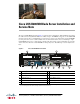
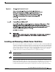
Cisco UCS B200 M3 Blade Server Installation and Service Note The Cisco UCS B200 M3 (shown in Figure 1) is the latest Cisco Intel-based, half-width blade supporting two CPU sockets using Intel E5-2600 series CPUs and up to 24 DIMMs; it supports one modular LOM (dedicated slot for Cisco's Virtual Interface Card) and one adapter card. At this time, the UCS B200 M2 (second generation) server is still available and is documented elsewhere.
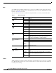
LEDs Server LEDs indicate whether the blade server is in active or standby mode, the status of the network link, the over all health of the blade server, and whether the server is set to give a flashing blue beaconing indication. See Table 1 for details. The removable hard disks also have LEDs indicating hard disk access activity and hard disk health. Table 1 Blade Server LEDs LED Color Description Off Power off. Green Normal operation. Amber Standby. Off None of the network links are up.
The beaconing function for an individual server may get turned on or off by pressing the combination button and LED. See Table 1 for details. The power button and LED allows you to manually take a server temporarily out of service but leave it in a state where it can be restarted quickly.
Safety warnings appear throughout this publication in procedures that, if performed incorrectly, can cause physical injuries. A warning symbol precedes each warning statement. Warning IMPORTANT SAFETY INSTRUCTIONS This warning symbol means danger. You are in a situation that could cause bodily injury. Before you work on any equipment, be aware of the hazards involved with electrical circuitry and be familiar with standard practices for preventing accidents.
Warnung WICHTIGE SICHERHEITSHINWEISE Dieses Warnsymbol bedeutet Gefahr. Sie befinden sich in einer Situation, die zu Verletzungen führen kann. Machen Sie sich vor der Arbeit mit Geräten mit den Gefahren elektrischer Schaltungen und den üblichen Verfahren zur Vorbeugung vor Unfällen vertraut. Suchen Sie mit der am Ende jeder Warnung angegebenen Anweisungsnummer nach der jeweiligen Übersetzung in den übersetzten Sicherheitshinweisen, die zusammen mit diesem Gerät ausgeliefert wurden.
Varning! VIKTIGA SÄKERHETSANVISNINGAR Denna varningssignal signalerar fara. Du befinner dig i en situation som kan leda till personskada. Innan du utför arbete på någon utrustning måste du vara medveten om farorna med elkretsar och känna till vanliga förfaranden för att förebygga olyckor. Använd det nummer som finns i slutet av varje varning för att hitta dess översättning i de översatta säkerhetsvarningar som medföljer denna anordning.
Aviso INSTRUÇÕES IMPORTANTES DE SEGURANÇA Este símbolo de aviso significa perigo. Você se encontra em uma situação em que há risco de lesões corporais. Antes de trabalhar com qualquer equipamento, esteja ciente dos riscos que envolvem os circuitos elétricos e familiarize-se com as práticas padrão de prevenção de acidentes. Use o número da declaração fornecido ao final de cada aviso para localizar sua tradução nos avisos de segurança traduzidos que acompanham o dispositivo.
Cisco UCS B200 M3 Blade Server Installation and Service Note 8 OL-26624-01
Installing and Removing a Blade Server Hard Drive Installing and Removing a Blade Server Hard Drive There are up to two front-accessible, hot-swappable, 2.5-inch drives per blade. An LSI SAS 2004 RAID controller is embedded in the motherboard (it is not separately replaceable), and it supports RAID 0 and 1. You can remove blade server hard drives without removing the blade server from the chassis. All other component replacements for a blade server requires removing the blade from the chassis.
Installing and Removing a Blade Server Hard Drive RAID volumes. If drives of different capacities are used, the useable portion of the smallest drive will be used on all drives that make up the RAID volume. Before upgrading or adding an HDD to a running system, check the service profile in UCS Manager to make sure that the new hardware configuration is within the parameters allowed by the service profile.
Removing and Installing a UCS B200 M3 Blade Server Installing a Hard Drive in a Blade Server 331363 Figure 4 2 1 Step 2 Gently slide the hard drive into the opening in the blade server until it seats into place. Step 3 Push the hard drive lever into the closed position. You can use UCS Manager to format and configure RAID services. Refer to the UCS Manager configuration guide for your software release for details on RAID configuration.
Removing and Installing a UCS B200 M3 Blade Server You can invoke a graceful shutdown or an emergency shutdown (hard shutdown) by using either of the following methods: • Use the UCS Manager. See either the Cisco UCS Manager GUI Configuration Guide or the Cisco UCS Manager CLI Configuration Guide. • Use the Power button on the server front panel. To use the Power button, follow these steps: Step 1 Step 2 Caution Step 3 Check the color of the Power Status LED.
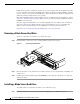
Removing and Installing a UCS B200 M3 Blade Server Installing a Cisco UCS B200 M3 Blade Server UCS B200 M3 blade servers are interoperable in a UCS chassis with any other UCS blade servers, including prior generation B200 M2 and B200 M1 servers, or other UCS B-Series blade servers. To install a blade server, follow these steps: Step 1 Grasp the front of the blade server and place your other hand under the blade to support it. See Figure 5.
Secure Digital (SD) Card Access Figure 5 shows the positioning of a blade server in the chassis. Blade servers reside within the eight upper slots of the chassis. Secure Digital (SD) Card Access SD card slots are provided for future usage. Their use is not supported at product release. They will require a future software update to be used.
Removing a Blade Server Cover Removing a Blade Server Cover To open a blade server, follow these steps: Step 1 Press and hold the button down as shown in Figure 7. Step 2 While holding the back end of the cover, pull the cover up and back.
Removing a Blade Server Cover Air Baffles The air baffles (shown in Figure 8) direct and improve air flow for the server components. Two identical baffles ship with each B200 M3 server. No tools are necessary to install them, just place them over the DIMMs as shown, with the holes in the center of the baffles aligned with the corresponding motherboard standoffs.
Removing a Blade Server Cover Once installed, the air baffles direct the intake air into four distinct lanes as shown in Figure 9. Cisco UCS B200 M3 Air Flow 331731 Figure 9 Internal Components Figure 10 calls out the various components within the blade server.
Working Inside the Blade Server 1. Cisco UCS-USBFLSH-S-4GB= is recommended, but if another USB drive will be used it must be no wider than .8 inches, and no more than 1.345 inches long in order tp provide needed clearances to install or remove the USB drive. Note Use of this server may require an upgrade to the IOM in the chassis. This server only supports third generation adapter cards, which have features requiring a Cisco 2204 or 2208 IOM, and are not backward compatible with the Cisco 2104 IOM.
Working Inside the Blade Server Installing a Motherboard CMOS Battery This server supports the CR2032 CMOS battery (N20-MBLIBATT). Warning There is danger of explosion if the battery is replaced incorrectly. Replace the battery only with the same or equivalent type recommended by the manufacturer. Dispose of used batteries according to the manufacturer’s instructions.
Working Inside the Blade Server Figure 11 Removing and Replacing a Motherboard CMOS Battery + C0 C1 C2 D0 D1 D2 B2 B1 B0 A2 A1 A0 331368 CPU 1 Removing and Installing a CPU and Heat Sink You can only order your blade server with two CPUs, but at some point you may choose to upgrade them to a different type. Both CPUs must be of the same type, and memory in slots intended for the second CPU will not be recognized if the second CPU is not present (see Memory Arrangement).
Working Inside the Blade Server Loosen one screw by a quarter turn, then move to the next in the X pattern shown in Figure 17 on page 26. Continue loosening until the heat sink can be lifted off. Step 2 Remove the heat sink. See Figure 12, callout 2. Remove the existing thermal compound from the bottom of the heat sink using the cleaning kit (UCSX-HSCK= ) included with each CPU option kit. Follow the instructions on the two bottles of cleaning solvent.
Working Inside the Blade Server Figure 13 Proper Alignment of CPU Pick and Place Tool (for Intel Xeon E5-2600 Series Processors) 2 1 Alignment mark on the button/handle of the pick and place tool 2 331370 1 Alignment mark on the socket Installing a New CPU and Heat Sink Before installing a new CPU in a server, verify the following: • The CPU is supported for that given server model.
Working Inside the Blade Server Protective Cap Removal 333565 Figure 14 To install a CPU and heat sink, follow these steps: Step 1 Release the catch on the pick and place tool by pressing the handle/button. Step 2 Remove the new CPU from the packaging, and load it into the pick and place tool as follows (see Figure 15): a. Confirm that the pedestal is set up correctly for your processor. The pedestal ships configured with the markings “LGA2011-R0” facing upward, and this is the correct orientation.
Working Inside the Blade Server Figure 15 Loading the Pick and Place Tool 1 1 1 333566 1 Alignment mark on the pick and place tool, CPU and pedestal Step 3 Place the CPU and tool on the CPU socket with the registration marks aligned as shown in Figure 16. Step 4 Press the button/handle on the pick and place tool to release the CPU into the socket.
Working Inside the Blade Server Figure 16 Using the CPU Pick and Place Tool to Insert the CPU 2 1 Alignment mark on the tool button/handle Step 5 Close the socket latch. See Figure 17, callout 1. Step 6 Secure the first hook, marked with an Step 7 Secure the second hook, marked with an 2 331370 1 Alignment mark on the CPU socket icon. See Figure 17, callout 2. icon. See Figure 17, callout 3.
Working Inside the Blade Server Figure 17 Replacing the Heat Sink (B200 M3 Shown) 3 4 2 1 5 4 5 5 5 1 3 331372 2 Step 8 Using the syringe of thermal grease provided with replacement CPUs and servers (and available separately as UCS-CPU-GREASE=, the only exceptions are Cisco UCS C220 M3 and and C240 M3 servers which use UCS-CPU-GREASE2= instead), add 2 cubic centimeters of thermal grease to the top of the CPU where it will contact the heat sink. Use the pattern shown in Figure 18.
Working Inside the Blade Server Caution Step 10 On certain models, heat sinks are keyed to fit into the plastic baffle extending from the motherboard. Do not force a heat sink if it is not fitting well, rotate it and re-orient the heat sink. Secure the heat sink to the motherboard by tightening the four captive screws a quarter turn at a time in an X pattern as shown in the upper right of Figure 17.
Memory and Performance Memory and Performance This section describes the type of memory that the B200 M3 blade server requires, and its effect on performance. The following topics are covered: • Supported DIMMs, page 28 • Memory Arrangement, page 28 • Memory Performance, page 31 • Memory Mirroring and RAS, page 31 Supported DIMMs The DIMMs that are supported in this blade server are constantly being updated.
Memory and Performance DIMMs and Channels Each channel is identified by a letter—A, B, C, D for CPU1, and E, F, G, H for CPU 2. Each DIMM slot is numbered 0, 1, or 2. Note that each DIMM slot 0 is blue, each slot 1 is black, and each slot 2 is off-white or beige. Figure 21 shows how DIMMs and channels are physically laid out on the blade server.
Memory and Performance Figure 22 shows a logical view of the DIMMs and channels.
Memory and Performance Table 2 Preferred DIMM Population Order DIMMs per CPU CPU 1 installed slots CPU 2 installed slots 4 (Blue slots) A0, B0, C0, D0 E0, F0, G0, H0 5 A0, B0, C0, D0 A1 E0, F0, G0, H0 E1 6 A0, B0, C0, D0 A1, B1 E0, F0, G0, H0 E1, F1 7 A0, B0, C0, D0 A1, B1, C1 E0, F0, G0, H0 E1, F1, G1 8 (Blue and black slots) A0, B0, C0, D0 A1, B1, C1, D1 E0, F0, G0, H0 E1, F1, G1, H1 9 A0, B0, C0, D0 A1, B1, C1, D1 A2 E0, F0, G0, H0 E1, F1, G1, H1 E2 10 A0, B0, C0, D0 A1, B1, C1,
Memory and Performance Installing a Modular LOM The Cisco VIC 1240 is a specialized modular Lan on Motherboard (mLOM) adapter that provides dual 2 x 10 Gb of Ethernet/ or Fiber Channel over Ethernet (FCoE) connectivity to each chassis. It plugs into the dedicated mLOM connector only. It is currently the only card that can be plugged into the mLOM connector and it will provide connectivity through either a 2100 series or 2200 series IOM. Note You must remove the adapter card to service the modular LOM.
Memory and Performance Installing an Adapter Card The network adapters and interface cards all have a shared installation process and are constantly being updated. A list of currently supported and available models for this server is in the specification sheets at this URL: http://www.cisco.com/en/US/products/ps10280/products_data_sheets_list.html Note If a VIC 1240 mLOM is not installed, you must have an adapter card installed.
Trusted Platform Module Figure 24 Installing an Adapter Card 3 2 1 331730 1 Trusted Platform Module The Trusted Platform Module (TPM, Cisco Product ID UCSX-TPM1-001) is a component that can securely store artifacts used to authenticate the server. These artifacts can include passwords, certificates, or encryption keys. A TPM can also be used to store platform measurements that help ensure that the platform remains trustworthy.
Server Troubleshooting Step 4 On the Advanced tab, select Trusted Computing and press Enter. Step 5 Set the TPM Support optionto Enable. Step 6 Press F10 to save and exit. Allow the server to finish booting. Server Troubleshooting For general server troubleshooting information, refer to the "Troubleshooting Server Hardware" chapter of the Cisco UCS Troubleshooting Guide. Server Configuration UCS servers are intended to be configured and managed using UCS Manager.
Related Documentation Obtaining Documentation and Submitting a Service Request For information on obtaining documentation, submitting a service request, and gathering additional information, see the monthly What’s New in Cisco Product Documentation, which also lists all new and revised Cisco technical documentation, at: http://www.cisco.com/en/US/docs/general/whatsnew/whatsnew.