
Specifications


3-16
Cisco UCS C240 Server Installation and Service Guide
OL-25761-01
Chapter 3 Maintaining the Server
Installing or Replacing Server Components
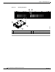
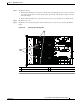
Step 9 Remove the SAS expander card from the backplane assembly:
a. Use a #2 Phillips-head screwdriver to remove the two screws that secure the SAS expander to the
backplane assembly steel tray (see
Figure 3-10).
b. Pull the SAS expander from the sockets on the drive backplane and then set the SAS expander aside
on an antistatic mat.
Step 10 Install the SAS expander card to the new backplane assembly:
a. Push the two connectors on the SAS expander into the two sockets on the backplane assembly.
b. Use a #2 Phillips-head screwdriver to install the two screws that secure the SAS expander to the
backplane assembly steel tray (see
Figure 3-10).
Step 11 Align the backplane assembly steel tray with the guides on the chassis walls, and then lower it evenly to
the chassis floor.
Step 12 Tighten the two captive thumbscrews that secure the backplane to the chassis.
Step 13 Reconnect the power harness cable to the motherboard connector BACKPLANE POWER1.
Step 14 If your server has a SAS expander, reconnect SAS cables to the SAS expander. (The SFF 16-drive
backplane option does not use an expander.)
Step 15 Reconnect all cables to the backplane.
Step 16 Replace all drives and drives trays to the drive bays.
Step 17 Replace the fan tray.
a. With the blue-plastic lever at each end of the fan tray in the upright and open position, set the fan
tray in place in the chassis. Use the chassis guides at each end of the fan tray to keep the fan tray
level and straight.
b. Rotate each blue-plastic lever down to the locked position. Stop when the levers click and lock.
Step 18 Replace the top cover.
Step 19 Replace the server in the rack, replace cables, and then power on the server by pressing the Power
button.