HVR-MRC1 SERVICE MANUAL US Model Canadian Model AEP Model E Model Chinese Model Japanese Model Ver. 1.2 2009.03 Revision History Revised-2 Replacement of the previously issued SERVICE MANUAL 9-852-266-12 with this manual. Link SPECIFICATIONS FRAME SCHEMATIC DIAGRAM REPAIR PARTS LIST SERVICE NOTE SCHEMATIC DIAGRAMS ADJUSTMENTS DISASSEMBLY PRINTED WIRING BOARDS INSTRUCTION MANUAL BLOCK DIAGRAMS The components identified by mark 0 or dotted line with mark 0 are critical for safety.
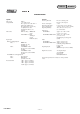
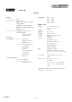
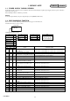
ENGLISH JAPANESE SPECIFICATIONS General System File system CompactFlash File format Power requirement FAT32 133x 2 GB or more The capacity is the value when 1 GB equals 1 billion bytes. The actual usable capacity may be slightly less because administrative files etc. are included. HDV recording MPEG-2TS (.m2t) DVCAM/DV recording AVI-Type1 (.AVI) RAW DV (.DV) Power consumption Operating temperature Storage temperature Operating humidity DC 7.2 V (battery pack) DC 8.4 V (AC adaptor) 2.
ENGLISH JAPANESE 概略仕様 システム ファイルシステム 録画可能時間 FAT32 コンパクトフラッシュ 133x 2 GB以上 容量は、 1 GBを10億バイトで計算し た場合の数値です。 約9 分 約18分 約36分 約72分 電源部・その他 また管理用ファイルなどを含むため、 電源電圧 実際使用できる容量は若干減少する場 合があります。 消費電力 ファイルフォーマット HDV記録時 MPEG-2TS(.m2t) 動作温度 DVCAM/DV記録時 AVI-Type1(.AVI) RAW DV(.DV) 保存温度 動作湿度 バッテリー端子入力 7.2 V DC端子入力 8.4 V 2.
ENGLISH SAFETY-RELATED COMPONENT WARNING!! COMPONENTS IDENTIFIED BY MARK 0 OR DOTTED LINE WITH MARK 0 ON THE SCHEMATIC DIAGRAMS AND IN THE PARTS LIST ARE CRITICAL TO SAFE OPERATION. REPLACE THESE COMPONENTS WITH SONY PARTS WHOSE PART NUMBERS APPEAR AS SHOWN IN THIS MANUAL OR IN SUPPLEMENTS PUBLISHED BY SONY.
ENGLISH JAPANESE サービス,点検時には次のことにご注意下さい。 6. フレキシブルプリント基板の取扱いについて 1. 注意事項をお守りください。 サービスのとき特に注意を要する個所については, キャビネット,シャーシ,部品などにラベルや捺印で • コテ先温度を270℃前後にして行なって下さい。 • 同一パターンに何度もコテ先を当てないで下さい。 注意事項を表示しています。これらの注意書き及び取 扱説明書等の注意事項を必ずお守り下さい。 (3回以内) • パターンに力が加わらないよう注意して下さい。 2. 指定部品のご使用を セットの部品は難燃性や耐電圧など安全上の特性を 7.
ENGLISH 1. SERVICE NOTE JAPANESE 1-1. POWER SUPPLY DURING REPAIRS In this unit, about 10 seconds after power is supplied to the battery terminal using the regulated power supply (8.4V), the power is shut off so that the unit cannot operate. These following method is available to prevent this. Method: Use the DC input terminal. (AC power adaptor/changer (AC-VQ1050B) and DK cable). 1-2. SELF-DIAGNOSIS FUNCTION When an error occurs the following warning indicators may appear on the LCD screen.
ENGLISH JAPANESE 1-1. 修理時の電源供給について 本機では,安定化電源(8.4Vdc)からバッテリ端子に電源を供給した場合,約 10 秒後にシャットオフし,動作しなくなります。 これを避けるため,下記の方法を用いてください。 方法: DC入力端子を使用する。(ACアダプタ/チャージャ(AC-VQ1050)とDKケーブルを使用する。) 1-2. 自己診断機能 エラーが発生した場合は,エラー内容に合わせて LCD 画面にエラーコードが表示されます。 また,カメラ側にエラーコードが送信されます。 LCD画面 ERROR A:12:01 自己診断表示:X:Yy:ZZ Y X i.
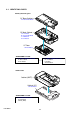
2. DISASSEMBLY NOTE FOR REPAIR • Make sure that the flat cable and flexible board are not cracked of bent at the terminal. Do not insert the cable insufficiently nor crookedly. • When remove a connector, don’t pull at wire of connector. It is possible that a wire is snapped. • When installing a connector, don’t press down at wire of connector. It is possible that a wire is snapped. HVR-MRC1 2-1 Cut and remove the part of gilt which comes off at the point.
2-1. IDENTIFYING PARTS Memory Recording Unit CF Base Cabinet ⋅ FP-202 Flexible Board CF Main Cabinet ⋅ CF-110 Board ⋅ FP-201 Flexible Board ⋅ LC-095 Board ⋅ TK-071 Board CF Door ⋅ SW-525 Board - DISASSEMBLY FLOW 2-2-1. BASE CABINET SECTION ⋅ CF Base Cabinet ⋅ TK-071 Board 2-2-2. MAIN CABINET SECTION ⋅ CF-110 Board ⋅ LCD Block ⋅ SW-525 Board i.LINK Cradle Cabinet (BATT) Cabinet (CF) ⋅ CR-090 Board - DISASSEMBLY FLOW 2-2-3.
HELP 2-2. DISASSEMBLY EXPLODED VIEW HARDWARE LIST 2-2-1. BASE CABINET SECTION Follow the disassembly in the numerical order given.
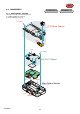
2-2-2. MAIN CABINET SECTION EXPLODED VIEW Follow the disassembly in the numerical order given. HARDWARE LIST 1 CF-110 Board (1-1 to 1-5) 2 LCD Block (2-1 to 2-2) 3 SW-525 Board (3-1 to 3-9) 1-2 (#46) 1-3 (#11) 1-5 1 CF-110 Board C F -1 10 2-1 1-1 2 LCD Block 3-7 (#11) 3-3 (#11) Note: Don't touch grease. A 3-6 (#46) 3-8 3 SW-525 Board Note: On installation of the SW-525 board, adjust the position of switch of CF door and S7010 of SW-525 board.
2-2-3. ADAPTOR SECTION EXPLODED VIEW Follow the disassembly in the numerical order given.
HELP Sheet attachment positions and procedures of processing the flexible boards/harnesses are shown.
3.
3. BLOCK DIAGRAMS 3-1. OVERALL BLOCK DIAGRAM ( ) : Number in parenthesis ( ) indicates the division number of schematic diagram where the component is located. MEMORY RECORDING UNIT M3.
3-2.
4. PRINTED WIRING BOARDS AND SCHEMATIC DIAGRAMS 4-1. FRAME SCHEMATIC DIAGRAM MEMORY RECORDING UNIT i.
4-2. SCHEMATIC DIAGRAMS Link TK-071 BOARD (1/5) (HDV/DV i.LINK INTERFACE) LC-095 BOARD (LCD) TK-071 BOARD (2/5) (MAIN CPU) SW-525 BOARD (CONTROL SWITCH) TK-071 BOARD (3/5) (SDRAM) FP-202 FLEXIBLE BOARD (HOT SHOE (MEMORY RECORDING UNIT)) TK-071 BOARD (4/5) (SUB CPU) TK-071 BOARD (5/5) (DC/DC CONVERTER) CF-110 BOARD (CF CONNECTOR) COMMON NOTE FOR SCHEMATIC DIAGRAMS HVR-MRC1 FP-203 FLEXIBLE BOARD (HOT SHOE (i.
4-2. SCHEMATIC DIAGRAMS ENGLISH JAPANESE 4-2. SCHEMATIC DIAGRAMS (ENGLISH) THIS NOTE IS COMMON FOR SCHEMATIC DIAGRAMS (In addition to this, the necessary note is printed in each block) (For schematic diagrams) • All capacitors are in µF unless otherwise noted. pF : µ µF. 50 V or less are not indicated except for electrolytics and tantalums. • Chip resistors are 1/10 W unless otherwise noted. kΩ=1000 Ω, MΩ=1000 kΩ. • Caution when replacing chip parts. New parts must be attached after removal of chip.
4-2.
2 1 5 4 3 7 6 8 10 9 11 12 A A FB4001 M3.3V F 40 D00 41 xPDIAG 42 D01 43 D08 44 D02 45 D09 46 GND(xIOIS16) 47 D10 48 GND(xCD2) 49 COVER_STAT 50 GND 51 0 R4057 0 R4056 0 CTL1 GND C4001 B 25V 0.01u 33 R4036 5600 R4019 82 R4020 33 0.4 LD[0] 0.
DDQ[30] DDQ[29] DDQ[28] DDQ[27] DDQ[26] DDQ[25] DDQ[24] DDQ[23] DDQ[22] DDQ[21] DDQ[20] DDQ[19] DDQ[18] DDQ[17] DDQ[16] DDQ[15] DDQ[14] DDQ[13] DDQ[12] DDQ[11] DDQ[10] DDQ[9] DDQ[8] DDQ[7] DDQ[6] DDQ[5] DDQ[4] DDQ[3] DDQ[2] DDQ[1] DDQ[0] DDQ[31] DDQ[31] XPD2 VSS25 XPD1 VSS26 XPD0 VSS27 CLK VSS28 PLL3FILTER VSS29 PLL2FILTER VSS30 PLL1FILTER VSS31 XPA0 VSS32 XPA1 VSS33 XPA2 VDD181 XPWR- IC5001 IND60C32A MAIN CPU VDD182 XPRD- VDD183 XPCS- VDD184 XPRINT
1 2 3 4 5 6 A A M3.
2 1 5 4 3 8 7 6 11 10 9 12 FB2001 LCD_RESET S3.3V LCD_CS1 R2053 R2010 R2009 R2008 R2006 R2005 R2004 R2003 R2002 R2001 LCD_A0 A 33k 33k 33k 33k 33k 33k 33k 33k 33k 10V C2006 B 0.1u R2034 R2035 15 R2036 1k SW_OFF_CN 13 12 STOP 11 GND R2037 R2012 R2013 R2014 1k R2038 1k R2020 GND 9 A0 8 GND 7 CS 6 GND 5 RES 4 GND 3 ENA 2 GND 1 3.0V B CF-110 1k CN8004 Through the Flexible Flat Cable (FFC-159) (Page 4-9) 1k 1k B 0.01u R2040 33k B 0.
• Refer to page 4-2 (English), 4-3 (Japanese) for mark 0. 2 1 5 4 3 8 7 6 11 10 9 12 IC1002 S-812C33BPI-C4NTFG 3.3V REG 6 5 2 1 ACV_UNREG 270k 0 0 C1034 0.1u B D1004 RSX101VA-30TR R1012 VOUT 1 C1045 0.1u 3.3 C1042 1u B 10V 10V 0 IC1003 TK11130CSCL-G 3V REG 3 2.3 SW_OFF 2.8 DCIN_AD R1006 18k Q1011 R1010 1800 Q1008 RTQ035P02TR B+ SWITCH (1.4A/32V) F1002 R1042 2.3 SET_UNREG 6 5 2 1 0 1u 10V C1006 0.01u B B C1002 1u 10V C1013 10u C C1007 0.
2 1 5 4 3 8 7 6 11 10 9 12 A A Note: CN8001 is not supplied, but this is included in CF-110 complete board.
1 2 4 3 5 6 8 7 9 10 11 12 A A CL6030 FB6001 B B R6007 300k R6008 390 R6009 150k R6010 510k C6012 10u C6013 0.1u C B GND 5 A0 6 GND 7 CS R6001 R6003 XX XX 8 GND 9 RES 10 GND 11 ENA 12 GND 13 3.0V Q6002 RTF015P02TL 3 3 R6024 33k 0 0 DTC144EMT2L Q6001 ENA 0.1u 470 CL-271TLY-C-TS D6002 R6005 C6002 470 1u Q6001, Q6002 LED DRIVE 3.3 C6001 R6004 D6001 CL-271TLY-C-TS D6001, D6002 (BACKLIGHT) R6013 33k R6014 33k 16V C 10V B 10V B C6003 1u C6004 0.
1 2 5 4 3 7 6 8 10 9 11 12 A 3 3 C7008 1 2 4 1 3 H PLAY C > , , . B S7007 D7007 1 0.01u 4 B 25V 2 S7005 C7005 0.01u 3 B 25V 1 D7005 EDZ-TE61-5.6B 4 4 REPEAT MENU S7002 2 0.01u C7002 B 25V EDZ-TE61-5.6B D7002 C 2 S7008 CAM LINK C7007 0.01u 3 B 25V 1 EDZ-TE61-5.6B 4 D7008 EDZ-TE61-5.6B 3 2 S7004 1 B 25V 4 D7004 EDZ-TE61-5.6B 2 S7001 0.01u C7001 B 25V EDZ-TE61-5.6B D7001 B C7004 0.
1 2 4 3 1 A TK-071 (1/5) CN4002 (Page 4-4) C A 1Pin 1Pin 4 3 A A B 2 1Pin 1Pin LND001 REG_GND REG_GND LND101 LND001 REG_GND REG_GND LND021 LND002 REG_GND REG_GND LND102 LND002 REG_GND REG_GND LND022 LND003 REG_GND UNREG LND103 LND003 REG_GND UNREG LND023 LND004 REG_GND UNREG LND104 LND004 REG_GND UNREG LND024 LND005 N.C ACV_UNREG LND105 LND005 N.C ACV_UNREG LND025 LND006 UNREG ACV_UNREG LND106 LND006 UNREG ACV_UNREG LND026 LND007 UNREG N.
• Refer to page 4-2 (English), 4-3 (Japanese) for mark 0. 2 1 5 4 3 7 6 8 11 10 9 12 FP-203 FLEXIBLE LND001 – LND020 (Page 4-12) BT901 BATTERY TERMINAL CN9001 BATT(+) 1 SW 2 CL9001 S SIG 3 CL9002 − BATT(-) 4 REG_GND REG_GND REG_GND REG_GND N.C UNREG UNREG ACV_UNREG ACV_UNREG N.C DETECT REG_GND REG_GND TPA- TPA+ REG_GND TPB- TPB+ REG_GND REG_GND 3 4 5 6 7 8 9 10 11 12 13 14 15 16 17 18 19 20 B F9001 (1.
4-3.
4-3. PRINTED WIRING BOARDS 4-3. PRINTED WIRING BOARDS (ENGLISH) THIS NOTE IS COMMON FOR PRINTED WIRING BOARDS • • : Uses unleaded solder. : Circuit board : Flexible board Pattern from the side which enables seeing. : pattern of the rear side (The other layers’ patterns are not indicated) • Through hole is omitted. • There are a few cases that the part printed on diagram isn’t mounted in this model. • C: panel designation • Chip parts.
TK-071 (6 layers) : Uses unleaded solder.
CF-110 (6 layers) : Uses unleaded solder.
LC-095 (6 layers), SW-525 (6 layers) : Uses unleaded solder.
CR-090 (6 layers) : Uses unleaded solder.
NOTE 5. REPAIR PARTS LIST NOTE: Characters A to Z of the electrical parts list indicate location of exploded views in which the desired part is shown.
5. REPAIR PARTS LIST 5. REPAIR PARTS LIST (ENGLISH) NOTE: • -XX, -X mean standardized parts, so they may have some differences from the original one. • Items marked “*” are not stocked since they are seldom required for routine service. Some delay should be anticipated when ordering these items. • The mechanical parts with no reference number in the exploded views are not supplied.
Ver. 1.2 2009.03 The changed portions from Ver. 1.1 are shown in blue. 5. REPAIR PARTS LIST DISASSEMBLY 5-1. EXPLODED VIEWS HARDWARE LIST 5-1-1. BASE CABINET SECTION ns ns: not supplied CN902 1 #53 ns 10 #53 9 8 11 (Note) 7 Note: There are differences in the label indication in each country/area. Use the correct part for the each camera or model. (See the chart below) #46 Note: 仕向によりラベル表示に相違があります。 下表を参照してカメラ本体の機種名・仕向に 合った部品を使用してください。 6 Main Model Part No.
Ver. 1.2 2009.03 The changed portions from Ver. 1.1 are shown in blue. 5. REPAIR PARTS LIST HARDWARE LIST DISASSEMBLY 5-1-2. MAIN CABINET SECTION #46 ns: not supplied #11 56 #11 57 C F -1 10 70 58 59 #11 #11 68 60 A 61 #46 62 55 63 54 53 S 64 -5 W 25 #11 65 #2 71 69 52 ns 51 ns 66 67 Ref. No. A Part No. Description Ref. No. Part No.
Ver. 1.2 2009.03 The changed portions from Ver. 1.1 are shown in blue. 5. REPAIR PARTS LIST DISASSEMBLY 5-1-3. ADAPTOR SECTION HARDWARE LIST #2 #2 ns: not supplied 112 ns #53 110 111 108 109 BT901 107 J901 105 106 #12 #12 113 #12 114 #12 #12 #1 102 104 101 103 CN903 #1 • Refer to page 5-1 for mark 0. Ref. No. Part No.
Ver. 1.2 2009.03 The changed portions from Ver. 1.1 are shown in blue. CF-110 CR-090 LC-095 5-2. ELECTRICAL PARTS LIST Ref. No. Part No. Description Ref. No. A-1490-526-A CF-110 BOARD, COMPLETE ********************** (CN8001 is not supplied, but this is included in CF-110 complete board.) Part No. Description < COMPOSITION CIRCUIT BLOCK > RB9001 1-234-400-21 CONDUCTOR, NETWORK (1005X4) < THERMISTOR > < CAPACITOR > C8001 1-100-567-81 CERAMIC CHIP 0.
Ver. 1.1 2008.06 The changed portions from Ver. 1.0 are shown in blue. Ref. No. Part No. LC-095 Description Ref. No.
Ver. 1.2 2009.03 The changed portions from Ver. 1.1 are shown in blue. Ref. No. Part No. TK-071 Description Ref. No. C2002 C2003 C2004 C2005 C2006 1-100-567-81 1-100-567-81 1-125-777-11 1-100-567-81 1-125-777-11 CERAMIC CHIP CERAMIC CHIP CERAMIC CHIP CERAMIC CHIP CERAMIC CHIP 0.01uF 0.01uF 0.1uF 0.01uF 0.
TK-071 Ref. No. Part No. Description FB3001 FB4001 FB4002 FB4003 1-400-915-21 1-400-915-21 1-400-915-21 1-400-331-11 INDUCTOR (EMI FERRITE) (2012) INDUCTOR (EMI FERRITE) (2012) INDUCTOR (EMI FERRITE) (2012) FERRITE, EMI (SMD) (1005) Ref. No.
TK-071 Ref. No. Part No. Description R2008 R2009 R2010 R2011 1-208-923-11 1-208-923-11 1-208-923-11 1-208-683-11 METAL CHIP METAL CHIP METAL CHIP METAL CHIP 33K 33K 33K 1K 0.5% 0.5% 0.5% 0.5% 1/16W 1/16W 1/16W 1/16W Ref. No. R2012 R2013 R2014 R2015 R2016 1-208-683-11 1-208-683-11 1-208-683-11 1-208-683-11 1-208-683-11 METAL CHIP METAL CHIP METAL CHIP METAL CHIP METAL CHIP 1K 1K 1K 1K 1K 0.5% 0.5% 0.5% 0.5% 0.
TK-071 Ref. No. Part No. Description Ref. No. < VIBRATOR > X4001 * X5001 1-781-045-21 VIBRATOR, CRYSTAL (24.576MHz) 1-813-856-11 OSCILLATOR, CRYSTAL (27MHz) HVR-MRC1 5-10 Part No.
• EXCEPT J MODEL Checking supplied accessories. CD-ROM (Note) “Manuals for Digital HD Video Camera Recorder” Note:HVR-MRC1 is the accessory of HDR-Z7J/Z7U/Z7N/Z7E/Z7P/ Z7C and HDR-S270J/S270U/S270N/S270E/S270P/S270C. Please refer to following CD-ROM that is those accessory for the Operating Instructions.
6. ADJUSTMENTS 6-1. Reading/Clearing of History Information The history information recorded in this set can be read and cleared by connecting the set to the PC with the i.LINK cable and using batch files. • Kind of history information This set records the following history information: 1 Error codes (latest 10 codes) 2 Accumulated POWER ON time (in minute) 3 Accumulated recording time (in minute) 4 Accumulated playback time (in minute) 5 Accumulated files created 6 Accumulated CF card detection count 1-1.
1-2. List of Service Tools J-1 J-3 J-2 iLINK cable (Commercial item) Personal computer (Note 1) J-4 AC Adaptor/Charger (AC-VQ1050) 1-479-580-11 Connecting cord (DK-215) 1-783-710-24 • Files used Folder Name Uploader File Name 1394API.dll Remarks For installation of exclusive driver 1394DIAG.sys 1394vdev.inf 1394vdev.sys port95nt.exe CMD1394.exe tnf.exe batch_e HISTORY_E.bat Reading of history information (English version) ERROR_E.bat Clearing of error code history POWER_E.
1-3. Installation of Driver 6. Select “Add a new hardware device” and click “Next”. Install the driver exclusive for confirmation of HVR-MRC1. Install the driver in the following procedures. Once this work is performed, further installation is not required later on. Note: If the PC restarts after the driver installation completes, starts from the procedure No. 15. 1. 2. 3. 4. Double-click “Port95nt.exe” in the Uploader folder. According to the installation wizard, begin the installation.
9. Click “Have Disk”. 12. Click “OK”. Fig. 6-1-11 13. Select “1394 Virtual Device” and click “Next”. Fig. 6-1-8 10. Click “Browse”. Fig. 6-1-9 Fig. 6-1-12 11. Select “1394vdev.inf” copied to the PC and click “Open”. 14. Click “Next”. Then, the installation starts. Fig. 6-1-10 Fig. 6-1-13 Note: When driver is installed, personaol computer might be reset. In this case, please proceed work from procedure 15 after starting the personal computer.
15. Confirm the result of driver installation. Open “System Properties” → “Device Manager”. 17. If “Unknown device” is displayed below “1394 Test Devices”, update the driver in the procedures below. Fig. 6-1-16 18. Right-click “Unknown devices” and select “Update Driver”. Fig. 6-1-14 16. If “1394 Virtual device” is displayed below “1394 Test Devices”, the installation is normally finished. Fig. 6-1-17 19. Select “Install from a list or specific location” and click “Next”. Fig. 6-1-15 Fig.
20. Click “Browse”. 22. After the installation completes, click “Finish”. 23. Open “Device Manager”. If “1384 Virtual Devices” is displayed below “1394 Test Devices”, the installation is normally finished. Fig. 6-1-19 21. Specify the location (Uploader) where the driver is saved and click “OK”. The installation starts. Fig. 6-1-21 Fig.
1-4. 1-5. Reading of History Information Clearing of Error Code History Note: The following shows a case that uses the batch file of English version. For Japanese version, use “HISTORY.bat”. Note: The following shows a case that uses the batch file of English version. For Japanese version, use “ERROR.bat”. Procedures 1. Double-click “HISTORY_E.bat” copied to the PC. 2. The command prompt starts up. Following the message, press the [ENTER] key of PC. Procedures 1. Double-click “ERROR_E.
1-6. 1-7. Clearing of Accumulated POWER ON Time Clearing of Accumulated Recording Time Note: The following shows a case that uses the batch file of English version. For Japanese version, use “POWER.bat”. Note: The following shows a case that uses the batch file of English version. For Japanese version, use “REC.bat”. Procedures 1. Double-click “POWER_E.bat” copied to the PC. 2. The command prompt starts up. Procedures 1. Double-click “REC_E.bat” copied to the PC. 2. The command prompt starts up.
1-8. 1-9. Clearing of Accumulated Playback Time Clearing of Accumulated Files Created Note: The following shows a case that uses the batch file of English version. For Japanese version, use “PB.bat”. Note: The following shows a case that uses the batch file of English version. For Japanese version, use “FILE.bat”. Procedures 1. Double-click “PB_E.bat” copied to the PC. 2. The command prompt starts up. Procedures 1. Double-click “FILE_E.bat” copied to the PC. 2. The command prompt starts up. Fig.
1-10. Clearing of Accumulated CF Detection Count Note: The following shows a case that uses the batch file of English version. For Japanese version, use “CFDET.bat”. Procedures 1. Double-click “CFDET_E.bat” copied to the PC. 2. The command prompt starts up. Fig. 6-1-34 • To execute, press the [ENTER] key of PC. The clearing of accumulated CF detection count will be executed. • To cancel, click “x” mark at the upper right of the command prompt window to close the command prompt window. 3.
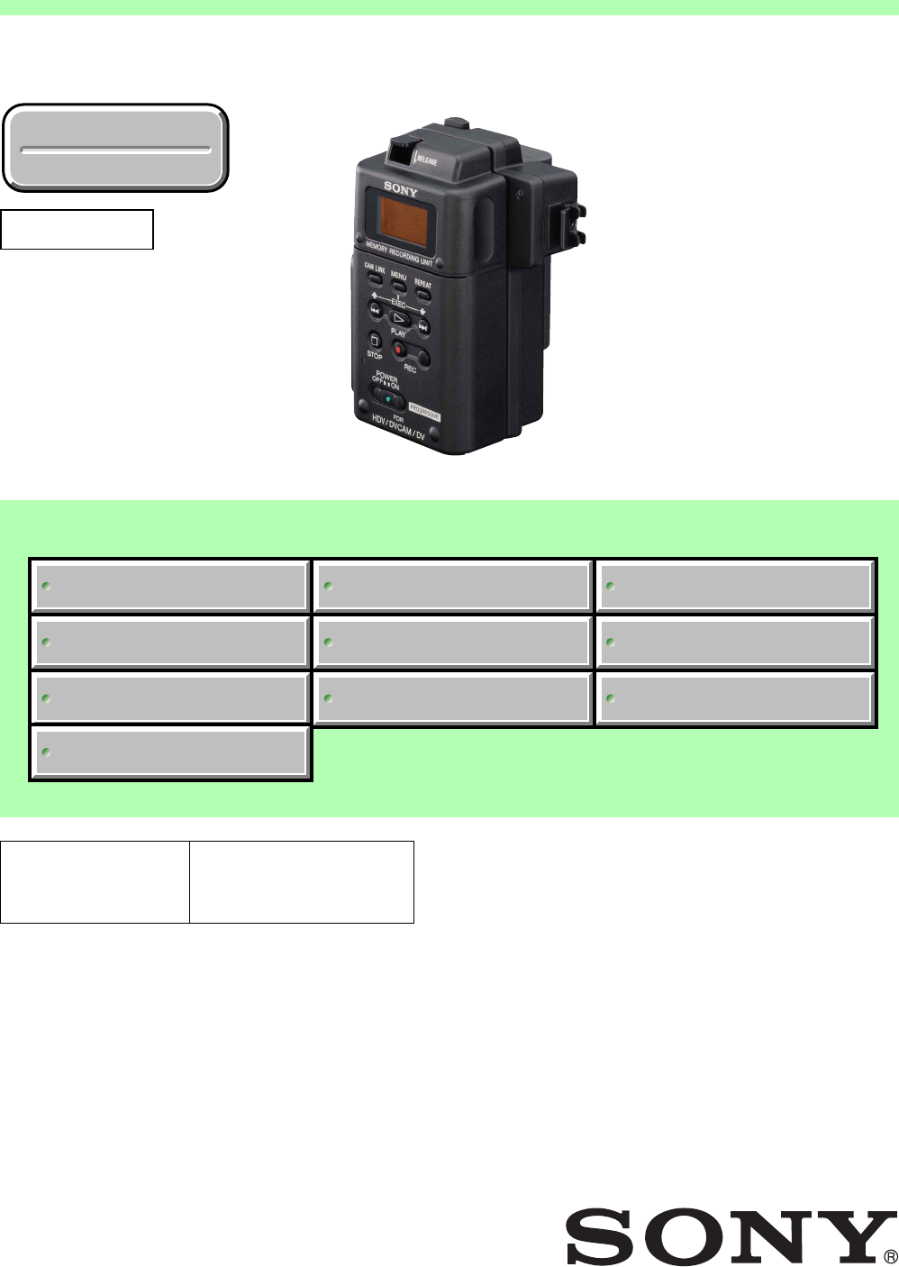
3-290-149-11(1) Memory Recording Unit Operating Instructions Owner’s record The model number and the serial number are located at the name plate on the left of the unit. Record the serial number in the space provided below. Refer to these numbers whenever you call upon your Sony dealer regarding this product. Model No. HVR- Serial No.
On trademarks Table of contents Overview ........................................................ 3 Names of parts ............................................... 4 Memory Recording Unit / i.LINK Cradle ...................... 4 LCD screen display ............................................................. 5 Using in VIDEO mode .................................... 6 Connecting this unit to a camcorder ................................ 6 Inserting/removing optional memory media ................
Overview Integrated architecture to the camcorder Supported models • The body is small and light with a weight of about 130 g and connects directly to a camcorder without a cable to provide camcorder mobility. Power is supplied from the camcorder so no additional battery is required; weight and size have thus been minimized. The power-saving design also enables longer recording time. • The operational status such as operating mode, remaining CompactFlash capacity or recording format, etc.
Names of parts Memory Recording Unit / i.LINK Cradle 1 qg 5 2 3 4 6 7 8 9 q; qa qs qd qf qh qj qk Attaching to the i.LINK cradle Attach this unit to the i.LINK cradle by sliding the unit in the direction of the arrow. 1 RELEASE button 9 PLAY/EXEC button Press this button to remove this unit. Press this button to play recorded files. Press this button during playback to pause playback. When the menu screen is displayed on the LCD screen, press this button to execute the selected menu item.
LCD screen display VIDEO mode During recording 1 2 During playback 3 4 5 qa 9 6 8 q; 7 1 Power supply display This icon is not displayed when this unit is connected directly to the camcorder. Displays the power supply icons when connected to a PC or camcorder using the i.LINK cradle. Battery pack in use Display the remaining battery capacity. AC adapter connected 2 CAM LINK mode display When the CAM LINK is set to ON, this icon is on. When the CAM LINK is set to OFF, this icon is off.
Using in VIDEO mode Connecting this unit to a camcorder Refer to the operating instructions of the camcorder. Connecting the shoe connector of the unit enables the camcorder to supply power and a stream signal. Removing the CompactFlash 1 Open the CompactFlash slot door and push the eject lever 1 to remove the CompactFlash. 2 Close the CompactFlash slot door.
Menu organization (VIDEO mode) root CLIP SELECT DELETE CLIP ALL FORMAT REC MODE NORMAL CACHE INTERVAL LOOP i.LINK MODE AUTO HDV DV SETTING TC FORMAT AUTO NDF DF DV FILETYPE AVI RAW DV INTERVAL REC TIME 0.5sec 1sec 1.5sec 2sec INT.TIME 30sec 1min 5min 10min CAMLINK SEL FOLLOW SYNCHRO SLEEP MODE OFF 1min 5min CAMERA NO ALL RESET * Boldface settings are default settings. CLIP SELECT REC MODE You can select the clip number directly.
SETTING TC FORMAT Follows the DF/NDF of the time code from the camcorder connected to this unit. • AUTO ....... Follows the time code format of the camcorder. • NDF ........... Records the time code in NDF format. • DF .............. Records the time code in DF format. Notes The default [AUTO] setting is NDF. If time code information from the camcorder is not obtained, this unit is set to the most recent recording setting. DV FILE TYPE Changes the DV recording format. • AVI ............
Recording images from the camcorder to this unit Images recorded by the camcorder can be recorded onto this unit. Recording images (POWER switch at the ON side) x Recording video simultaneously on this unit and a camcorder – Connecting to a camcorder with an “external REC control” function (SYNCHRO mode) When connected to a camcorder that has an external REC control function, this unit can be controlled by the camcorder to record video data simultaneously to the camcorder recording on tape.
x Recording on this unit during camcorder tape replacement When connected to a camcorder that has an external REC control function, you can record video on this unit only while changing the tape of the camcorder. Cache recording mode The most recent approximately maximum 14 seconds of video and audio captured by the camcorder are held in a buffer memory and automatically recorded when the recording button is pressed.
Loop recording mode Repeats overwrite-recording using the available space on the CompactFlash. You cannot select this mode if the remaining recording time is less than 5 minutes (CompactFlash icon is flashing). Setting loop recording mode Select [LOOP] from [REC MODE] on the menu screen. LCD screen display in loop recording mode Remains on during recording Notes • The speed will slow according to the volume of data being written because of limitations of the CompactFlash capacity.
Playback the image recorded on a CompactFlash in this unit To play back video clip recorded on a CompactFlash in this unit, you need to connect this unit to a playback device via an i.LINK cable. Playback (POWER switch to ON) Trick playback When the playback image is output to i.LINK, the clip is played at 3x, 6x, and 9x the normal speed. To play back at the changed speed To select the playback format Keep pressing . or > button during playback to start playback at the changed speed.
Useful functions in combination with HVR-Z7/S270 Tapeless external REC control Even if there is no tape in the HVR-Z7/S270, you can start or stop recording the image on this unit. You can record the time code of the HVR-Z7/S270 without a tape in the HVR-Z7/S270. If you want to record video using the time code of the HVR-Z7/S270, set the time code setting of the HVR-Z7/S270 as follows. Time code value always advances. Set the EXT REC CTRL setting of the HVR-Z7/S270 as follows. • TC MAKE ........
Display the operational status of this unit on the HVR-Z7/S270 LCD screen CAMERA mode – Indicators – Status check indicator • The following information can be displayed on the LCD screen of the HVR-Z7/S270. • The following information can be displayed on the status check indicator (CAMERA mode) of the HVR-Z7/S270. 1 2 1 CompactFlash connecting status This icon blinks when the remaining recording time of the CompactFlash is low or an error has occurred in this unit.
VCR mode – Indicators – Status check indicator • The following information can be displayed on the LCD screen of the HVR-Z7/S270. • The following information can be displayed on the status check indicator (VCR mode) of the HVR-Z7/S270. 2 1 3 4 1 CompactFlash connecting status This icon blinks when the remaining recording time of the CompactFlash is low or an error has occurred in this unit. PB FORMAT 2 CompactFlash mode The same icon as the mode icon of this unit is displayed.
Using in COMPUTER mode Connecting to a computer You can transfer recorded images on this unit as a file in HDV or DV format to a nonlinear editing system or computer. 1 Attach the HVRA-CR1 i.LINK cradle and optional AC adaptor to this unit. For extended use, the AC adaptor is recommended. This unit can still be operated with the battery pack attached. 2 Connect this unit to the computer via the optional i.LINK cable. 3 Slide the POWER switch of this unit to ON.
Menu organization (COMPUTER mode) root HDV DV-NTSC DV-PAL DRIVE SETTING TC FORMAT AUTO NDF DF DV FILETYPE AVI RAW DV CAMERA NO *Boldface settings are default settings. HDV Operate in the VIDEO mode. Set this mode when reading or writing HDV stream data on a CompactFlash in this unit using editing software. DV-NTSC Operate in the VIDEO mode. Set this mode when reading or writing DV (NTSC format) stream data on a CompactFlash in this unit using the editing software. DV-PAL Operate in the VIDEO mode.
Folder saving format Folder organization The file/folder organization of this unit is as follows. Media ROOT VIDEO HVR XX_CCCC_YYYY-MM-DD_hhmmss.M2T XX_CCCC_YYYY-MM-DD_hhmmss.IDX XX_CCCC_YYYY-MM-DD_hhmmss.M2T XX_CCCC_YYYY-MM-DD_hhmmss.IDX XX_CCCC_YYYY-MM-DD_hhmmss.AVI XX_CCCC_YYYY-MM-DD_hhmmss.IDX XX_CCCC_YYYY-MM-DD_hhmmss.AVI XX_CCCC_YYYY-MM-DD_hhmmss.IDX An actual file name has numbers as the following information. XX_CCCC_YYYY-MM-DD_hhmmss.DV • XX : Camera No. (00 to 99) • CCCC : Clip No.
Notes regarding COMPUTER mode • Do not save other data files in the HVR folder. • Do not transfer data from a computer to this unit in COMPUTER mode. Write back data from a computer to this unit by streaming. Write back data after selecting HDV or DV-NTSC, DV-PAL format in PC MODE in the menu. • Do not change folder or file names on your computer. Delete data or format a CompactFlash on this unit to increase the capacity of the CompactFlash.
Power supply Preparing the power supply The following will explain the optional AC-VQ1050 AC adaptor/charger. To charge the battery pack When using an “InfoLITHIUM” battery pack (L-series, optional) as the power supply for this unit, charge the battery back as follows before use. When charging the battery pack, refer to the operating instructions supplied with the AC adaptor/charger (optional).
AC adaptor/charger Do not short-circuit the DC plug of the AC adaptor/charger or battery terminal with any metallic objects. This may cause a malfunction. To install the battery pack to this unit To connect this unit to a wall outlet For prolonged operation, such as playing the recorded images, you can operate this unit from a domestic wall outlet without worrying about battery life. 1 Slide the battery pack in the direction of the b mark on the battery pack.
Trouble shooting Please check the following before contacting your Sony dealer. Note in case of repairs • Some kinds of repair work may require that the CompactFlash be formatted or replaced. In either case, all data on the CompactFlash will be deleted. Back-up your data from the CompactFlash before sending it for repairs. Sony does not guarantee against data being deleted during repair work.
Connecting a computer Symptom Cause/Remedy An error message appears when you place the supplied CD-ROM in your computer. t Set the computer display as follows: – 1024 × 768 dots or more, high color (16 bits, 65,000 colors) or more. The image or sound on this unit cannot be played back correctly. • Depending on the computer you are using, the played back image or sound may stop temporarily, but this does not affect the images or sound copied to your computer.
Warning indicators Self-diagnosis display When an error occurs the following warning indicators may appear on the LCD screen. Message A:ss:ss/I:ss:ss/P:ss:ss/ M:ss:ss/F:ss:ss/X:ss:ss (Self-diagnosis display) Cause/Corrective Action If an error recurs after you repeat corrective action several times, contact Sony Customer Service or the place of purchase. A:12:s • CompactFlash-related error has occurred. t Transfer speed of the CompactFlash may be slow.
Caution message Message Cause/Corrective Action • Displays when inserting an incompatible CompactFlash into this unit. t Use the recommended type of CompactFlash. • Displays when not formatting a CompactFlash with this unit etc. t Format the CompactFlash using this unit. * When this message is displayed, press the STOP button on this unit to display the screen for formatting a CompactFlash. • The CompactFlash you are using may be damaged. t Check the type you are using.
About i.LINK The HDV/DV jack provided on this unit is an i.LINKcompliant jack. This section describes the i.LINK standard and its features. What is i.LINK? i.LINK is a digital serial interface for sending and receiving digital video, digital audio, and other data between this unit and other equipment equipped with an i.LINK terminal. You can also control other equipment using i.LINK. i.LINK-compatible equipment can be connected using an i.LINK cable.
Optional CompactFlash CompactFlash • A CompactFlash 133x 2 GB or higher is recommended for use with this unit. (A speed of less than 133x is not guaranteed; space less than 2GB is not guaranteed.) • When using a CompactFlash for the first time, be sure to format it with this unit. • Data may be corrupted or the CompactFlash may not work in the following cases. – If you remove the CompactFlash during data reading/ writing. – If you move the CompactFlash close to a strong magnetic field.
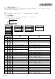
Specifications System File system CompactFlash File format FAT32 133x 2 GB or more The capacity is the value when 1 GB equals 1 billion bytes. The actual usable capacity may be slightly less because administrative files etc. are included. HDV recording MPEG-2TS (.m2t) DVCAM/DV recording AVI-Type1 (.AVI) RAW DV (.
Precautions On use and care x To clean the LCD screen • Do not use or store this unit and accessories in the following locations. – Anywhere excessively hot or cold. Never leave them exposed to temperatures above 60 °C (140 °F), such as under direct sunlight, near heaters or in a car parked in the sun. They may cause malfunction or become deformed. – Near strong magnetic fields or mechanical vibration. This unit may cause malfunction. – Near strong radio waves or radiation.
Getting the best performance from the battery pack • If the ambient temperature is low, the battery pack performance deteriorates, reducing the operating time. To maximize the operating time, the following techniques are recommended. – Keep the battery pack warm in a pocket, and load it into the unit immediately before shooting. • The battery is depleted when this unit is in recording standby or playback pause. Always switch off the power supply to save energy.
Additional information on this product and answers to frequently asked questions can be found at our Customer Support Website.
HARDWARE LIST (1/7) #1: M1.7 X 2.5 (Black) 2-635-562-11 #2: M1.7 X 4.0 (Black) 2-635-562-31 #3: M1.7 X 2.5 (Red) 2-660-401-01 1.7 2.5 1.7 4.0 #5: M1.7 X 3.5 (Tapping) (Black) 3-080-204-01 #11: M1.7 X 4.0 (Tapping) (Silver) 3-078-890-11 1.7 1.7 4.0 #13: M1.7 X 2.5 (Tapping) (Silver) 3-085-397-01 1.7 1.7 2.5 #16: M1.4 X 2.5 (Silver) 2-586-337-01 2.5 #19: M1.2 X 4.0 (Tapping) (Red) 3-086-156-21 1.4 1.5 2.5 1.4 1.4 1.5 #18: M1.4 X 2.5 (Silver) 2-635-591-21 1.7 2.2 1.7 5.0 #15: M1.4 X 1.
HARDWARE LIST (2/7) #21: M1.4 X 3.0 (Black) 2-662-396-21 #22: M1.7 X 5.0 (Tapping) (Silver) 3-083-261-01 #23: M1.7 X 4.0 (Tapping) (Black) 3-080-204-11 1.7 1.4 5.0 3.0 #25: M1.7 X 3.0 (Black) 2-635-562-21 3.0 3.0 #36: M3.0 X 6.0 (Silver) 4-886-821-11 3.0 4.0 6.0 6.0 #38: M3.0 X 20.0 (Tapping) (Silver) 7-685-651-79 2.0 4.5 #35: M4.0 X 6.0 (Tapping) (Silver) 3-975-291-02 8.0 #37: M2.0 X 6.0 (Tapping) (Black) 3-080-206-31 3.0 4.0 #34: M3.0 X 8.0 (Black) 3-077-331-41 6.0 #32: M2.0 X 4.
HARDWARE LIST (3/7) #41: M3.0 X 8.0 (Tapping) (Silver) 3-065-748-01 #42: M2.0 X 4.0 (Tapping) (Silver) 7-628-253-00 #43: M1.7 X 4.0 (Red) 2-660-401-31 3.0 8.0 2.0 #46: M1.7 X 3.0 (Red) 2-660-401-11 1.7 3.0 #49: M2.0 X 4.0 (Black) 2-630-005-31 2.0 4.0 #48: M1.7 X 2.5 (Silver) 3-973-497-91 1.7 1.4 2.5 3.0 #50: M2.0 X 3.0 (Red) 2-891-494-11 1.7 3.0 #47: M1.4 X 3.0 (Tapping) (Silver) 2-665-774-01 1.4 2.5 1.7 4.0 4.0 #45: M1.4 X 2.5 (Silver) 2-587-151-01 #44: M1.7 X 3.
HARDWARE LIST (4/7) #61: M3.0 X 10.0 (Black) 7-682-549-09 #62: M2.0 X 3.0 (Silver) 3-080-202-21 3.0 10.0 2.0 12.5 #66: M1.4 X 1.4 (Silver) 2-635-591-41 1.4 3.5 2.0 4.0 3.5 3.5 #76: M1.7 X 4.0 (Tapping) (Silver) 2-666-551-11 1.7 4.0 #79: M1.4X 2.0 (Silver) 2-587-151-11 #80: M1.4X 2.0 (Black) 3-279-411-01 1.4 1.4 1.2 2.0 1.7 1.7 #78: M1.4 X 3.5 (Red) 3-208-537-11 1.4 1.4 #75: M1.7 X 3.5 (Tapping) (Silver) 2-666-551-01 6.0 #77: M1.2 X 5.0 (Tapping) (Silver) 3-086-156-31 #72: M1.
HARDWARE LIST (5/7) #83: M1.7 X 7.0 (Tapping) (Black) 3-080-204-41 #82: M1.4 X 1.4 (Silver) 3-272-251-01 #81: M1.7 X 2.5 (Silver) 2-515-756-01 1.4 1.7 2.5 2.5 #90: M1.7 X 3.0 (Silver) 3-271-395-01 #91: M1.7 X 3.0 (Tapping) (Silver) 2-695-434-11 3.0 #97: M1.4 X 2.5 (Black) 2-662-396-31 1.4 1.4 3.0 2.5 #99: M2.5 X 6.0 (Tapping) (Silver) 3-776-750-02 3.8 8.0 #96: M1.4 X 2.5 (Silver) 2-587-151-21 8.0 #98: M3.0 X 8.0 (Silver) 3-077-331-01 2.5 3.9 #95: M3.0 X 8.
HARDWARE LIST (6/7) #102: M2.6 X 8.0 (Black) 7-621-284-30 #101: M2.0 X 5.0 (Silver) 7-621-555-39 2.6 2.0 5.0 #105: M2.0 X 4.0 (Red) 2-891-494-31 10.0 #106: M2.0 X 6.0 (Black) 3-713-786-11 #107: M2.0 X 5.0 (Silver) 3-032-750-01 2.0 4.0 6.0 #109: M1.7 X 3.0 (Black) 2-515-483-21 #110: M2.0 X 3.0 (Black) 2-630-005-21 5.0 #117: M1.7 X 4.5 (Tapping) (Silver) 2-695-429-31 #115: M1.4 X 3.5 (Tapping) (Silver) 3-348-998-51 1.4 #116: M2.0 X 3.5 (Tapping) (Silver) 2-695-435-01 2.0 1.4 3.
HARDWARE LIST (7/7) #121: M2.0 X 4.0 (Tapping) (Silver) 3-080-205-11 #122: M3.0 X 6.0 (Black) 7-682-547-09 3.0 2.0 4.0 #123: M4.0 X 8.0 (Black) 7-682-561-09 6.0 #124: M1.7 X 2.0 (Silver) 2-599-475-01 4.0 8.0 1.7 2.
Reverse 985226613.pdf Revision History Date 1.0 2008.01 Official Release 1.1 2008.06 Revised-1 (A1 DI08-162) • Change of Repair Parts S.M. revised: Page 5-5, Page 5-6, Page 5-7 Yes 1.2 2009.03 Revised-2 (A2 DI08-386) • Change of Repair Parts S.M. revised: Page 5-2, Page 5-3, Page 5-4, Page 5-5, Page 5-7 Yes HVR-MRC1 History Contents S.M. Rev. issued — Ver.