Cissi Form Finisher Models FCCG FCFG FCCD FCAC OWNER’S MANU AL MANUAL CISSELL MANUFACTURING COMPANY HEADQUARTERS 831 SOUTH FIRST ST. P.O. BOX 32270 LOUISVILLE, KY 40232-2270 PHONE: (502) 587-1292 SALES FAX: (502) 585-3625 SERVICE/PARTS FAX: (502) 681-1275 THIS MANU AL MUST BE GIVEN TO THE EQUIPMENT OWNER.
WARRANTY The Cissell Manufacturing Company (Cissell) warrants all new equipment (and the original parts thereof) to be free from defects in material or workmanship for a period of one (1) year from the date of sale thereof to an original purchaser for use, except as hereinafter provided.
TABLE OF CONTENTS GENERAL INFORMATION Warranty ...................................................................................................................... 1 Cissi Form Finisher Features ..................................................................................... 3-4 SPECIFICATIONS Motor, Steam Pressure, Weights .................................................................................. 4 Outline Dimensions ...........................................................................
CISSI FORM FINISHER Loving Care for Garments CISSELL FINISHER HELPS GIVE ORIGINAL LOOK TO ANY GARMENT (1) Sturdy, stainless steel, rust-resistant frame. (2) Controlled porosity nylon bag for better steam and air distribution. (3) Cleanable inlet air filter reduces bag replacement; helps keep garments clean. (4) Flow of air shapes garment whether heavy or light material. (5) Clamps. (6) Easily adjustable steaming; conditioning and drying controls. (7) Steam evenly distributed throughout entire form.
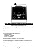
TOWER FEA TURES FEATURES • Steaming Timer w/Light • Conditioning Timer w/Light • Drying Timer w/Light • Push Button Start Switch • 3 Position Cycle Switch: 1. Steam and Air Conditioning, Drying; 2. Steaming, Conditioning, Drying; 3.
Page 6
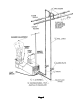
CISSI Installation Instructions Refer to illustration sheet (1) UNCRATE MACHINE. Check the nameplate voltage and current, making sure it is the same as the supply voltage and current. (2) SET MACHINE IN POSITION. (3) REMOVE THE REVOLVING FORM by holding the turning knob and the opposite weight “bucket” and lifting approximately 22”. (4) CONNECT STEAM SUPPLY LINE as shown on next page. (5) CONNECT RETURN LINE as shown on next page.
Page 8
Page 9
OPERA TION INSTRUCTIONS FOR “CISSI” FORM FINISHER OPERATION (Machine can be operated from either side). 1. Position garment on form and adjust shoulders. A knob on top of the form is used to adjust the form shoulder width. Turn knob clockwise to increase shoulder width. Turn knob clockwise to increase shoulder width. 2. Press white switch to “air on” to size the bag by moving the damper control on top of the tower. 3. Set the time on each timer.
CISSI FORM FINISHER The “Tower of Power” is at your fingertips for all of the finishing combinations you will ever need. All three timers (steaming, conditioning, drying) are adjustable from 0 to 30 seconds. The cycle switch provides (presteam only, steaming-conditioning-drying, steam & air-conditioning-drying) which ever is required. The white switch allows you to have air only for sizing and provides a cancel position to terminate the cycle at any time.
NET OVERBAG FOR CISSELL STEAM-AIR FINISHER (Either Genie or Garment Manufacturer’ sF orm having an “A” type frame) Manufacturer’s Form This overbag is for use ONLY when finishing sweaters or other soft garments that do not require bag contact for proper finishing. DO NOT use overbag with hard fabrics or heavy garments. Hard set wrinkles will not be removed when using the overbag.
CHANGING INSTRUCTIONS F833 Bag with GENIE Revolving Assembly TO REPLACE BAG TO REMOVE BAG (1) Remove yellow weights, 1 each side. (4) Replace yellow weights, one each side, on end of control strings. (2) Raise the lower control ring (inside bag). (3) Lower the control ring inside bag. (3) Open zipper and untie bottom string. (2) Tie bottom string in groove and close zipper. Refer to instructions on next page for proper knot when tying string. Straighten bag until control strings are at the sides.
INSTRUCTIONS FOR TYING LOWER TIE STRING Page 14
CISSELL STEAM-AIR FINISHER INSTRUCTIONS FOR ADJUSTING HEIGHT OF REVOL VING FORM REVOLVING (Model FM** and Model FG2) Should the revolving form “drag” on the base rather than turn freely, the form must be raised. Conversely, if the revolving form hides too high above the base, permitting steam to escape from the space between the form and base, the form must be lowered. WHEN AN ADJUSTMENT MUST BE MADE, REMOVE REVOLVING FORM BY SIMPLY LIFTING IT STRAIGHT UP OFF THE BASE.
SOLENOID LINKAGE ADJUSTMENT TO ADJUST STEAM VALVE AND SOLENOID LINKAGE: 1. Set steam valve extension bar and solenoid lever at 90º as shown and tighten set screw. Adjust steam valve adjusting nuts until 1/32” to 1/16” gap is obtained as shown above and lock adjusting nuts tightly together.
MO TOR MOUNTING DIMENSIONS MOT Page 17
SERVICE CHART PROBLEM CA USE CAUSE (1) No Steam 1A Steam Supply Valve “OFF” 1B Electric power”OFF” (2) Blower motor will start, steam won’t start 2A Start switch not released by cam when control knob is pushed 2B Loose wires 2C Incorrect voltage of electrical parts 2D Defective start switch 2E Defective solenoid 2F Defective solenoid linkage (3) Leaking steam valve 3A Solenoid linkage adjusted incorrectly 3B Loose valve seat 3C Worn valve (4) Wet steam 4A Trap not operating 4B Trap installed inco
PROBLEM (4) Wet steam (Cont.
PROBLEM (7) Blower motor won’t start, machine won’t steam (Cont.) CA USE CAUSE 7B Incorrect supply voltage 7C Air switch not being operated by cam lever 7D Defective air switch 7E Defective Automatic relay 7F Air timer set at 0 time 7G Defective blower relay 7H Defective blower motor (8) Blower motor won’t start, machine steams continuously after air switch is operated. (9) Blower motor will start, machine steams only while control knob is pushed.
PROBLEM (10) Inadequate steam flow CA USE CAUSE 10A Steam valve linkage not properly adjusted 10B Steam time set too short (11) Blower motor will 11 Defective steam timer (12) Blower motor won’t stop 12A Defective Air timer 12B Defective blower relay 12C Defective automatic relay (13) Blower motor starts, but form will not change 13A Damper control rod disconnected or broken Page 21 REMEDY Adjust linkage according to adjustment instructions. Tighten all set screws and lock nuts.
REVOL VING FORM - FG236 REVOLVING Ref. No. Part No. Description F517 ADJUSTABLE SHOULDER ASSEMBLY F381 Ass’y. { 12 3 4 5 6 7 8 9 10 D18 F47 Adjusting Knob w/Roll Pin C.R.S. Rod F49 F192 F492 F493 F336 F494 F197 F317 Shoulder Lever Pin Pyroid Gasket (2 req’d.) Shoulder Sliding Shoulder (2 req’d.) Shoulder Connecting Link (2 req’d.
INST ALLA TION INSTRUCTIONS INSTALLA ALLATION FOR AF 177 SWITCH 1. Turn switch to upside down position and remove (2) screws marked (a) as illustrated. 2. Lift off base plate pad. 3. Remove two (2) screws marked (B) as shown. 4. Remove two (2) washers, plate, insulation and switch. 5. Remove wires from old switch (C) and install wires on new switch and tighten securely. 6. Reinstall switch, insulation, plate, washers and screws and tighten securely. 7.
TOWER OF POWER P ARTS PARTS Ref. No. 1 2 3 4 5 6 7 8 9 10 11 12 13 14 15 16 Ref. No. Part No. Description FG453 PT74 PT107 PT111 AT245 FC59 PT118 RC385 M102 M454 PT182 PT183 FG144 FG233 TU13224 TU13225 M262 FC73 F943 LB291 Timer Rocker Switch Switch Spacer Push Button Switch Toggle Switch Control Panel Label Knob Machine Screw Lamp - 120 V. Lamp - 240 V. Relay - 120 V. Relay - 240 V. Relay - 120 V. Relay - 240 V. Relay - 120 V. Relay - 240 V.
CISSI REAR BASE ASSEMBL Y ASSEMBLY Ref. No. 1 2 3 4 5 6 7 8 9 10 11 12 13 14 15 16 17 18 19 Ref. No. Part No. Description FG342 FC47 PIU94 TU3549 P126 CB36 F739 F738 FC42 F520 F519 FC89 FC91 TU49 FC98 FC97 FC54 FG143 OP296 FC55 #6 - 32 x 3/4 Rd. Hd. Sc. Rear Base Rating Nameplate Rubber Bumper 1/4 - 20 x 1/4 Set Screw 1/4 - 20 x 1/2 Hex Hd. Sc. Solenoid 115 V. Solenoid 230 V. Solenoid Rod Extension Seal Spring Nylon Seal Damper Pull Rod Damper Lever Delrin Bearing Damper Rod Damper Blk.
CISSI SHALLOW BASE Ref. No. 1 2 3 4 5 6 7 8 9 10 11 12 13 Part No. Description Ref. No. F149 FG320 F215 FG275 TU49 F539 TU4593 LB20 FG319 F357 FG321 FG322 FC1 Steam Valve Pull Rod Extension Bar Set Collar (2 Req’d.) Steam Valve Lever Ass’y Delrin Bearing Stm. Chamber 1/2” x 90º Pipe Elbow 1/2” Pipe Nipple 3” Long Stm. Coil Adapter Felt Air Seal Steam Manifold Steam Coil Base Welded Ass’y Part No.
VAL VE P ARTS ALVE PARTS Ref. No. Part No. 1 2 3 4 5 6 7 8 9 F287 F286 F285 FV101 OP547 FV106 F18 F894 F896 FV110 10 11 12 13 14 15 16 17 18 19 20 FV100 V36 P103 F359 FV103 V15 V16 FV104 V330 FV105 F358 Page 27 Description Bearing Adjustment Scr. Bearing Lockout Bearing Support Box Valve Lever Locknut Collar Retainer Steam Spreader Drawband Drawband Eye Valve Ass’y CONSISTS OF REF. NO. 10-20 Valve Body Valve Seat Gasket “E” Ring Valve Stem Small Locknut Teflon Disc Valve Disc Holder 30 Lb.
BLOWER, MO TOR & MO TOR MOUNT MOT MOT Ref. No. Part No. Description 1 2 3 4 5 6 7 8 9 10 11 FG292 FG226 AF131 AF130 FG148 Motor C363 TU2814 C249 TU2793 M263 Blower Wheel Inlet Cone Motor Bracket Motor Bracket Mtg. Hardware Nylon Wire Clamp (Give Electrical Specs) 5/16” x 18 x 1 1/4” Cap Scr. 5/16” Split Lockwasher 5/16” - 18 Hex. Nut #8 x 5/8” S.M.S. #8 x 3/8” S.M.S.
JACKET & FIL TER FILTER Ref. No. Part No.
DAMPER CONTROL ASSEMBL Y ASSEMBLY FC63 Ref. No. Part No. Description 1 2 3 4 5 6 7 8 9 10 11 12 13 14 D16 F750 FC62 RC344 TU2847 F660 F639 TU4934 SV332 F664 F358 FC68 FC69 FC70 Control Handle Knob * Control Handle Shaft * Damper Control Lever 1/4” - 20 x 3/4” Hex Cap Screw 1/4” Flat Washer Rubber Washer Friction Washer 1/4” - 20 Hex Nut #8 - 32 x 3/8” Round Hd. Screw Swivel “E” Ring Damper Control Tube * Damper Control Wire * Tube & Wire Assembly * * Not included in FC63 Assembly, order separately.
OVERHEAD WATER SPRA Y GUN SPRAY Water Spray Gun Water Hose Assembly Complete Assembly - SG043 Repair Kit - SK043 Consists of: (Parts to repair one spray gun) Includes fittings, gaskets, and ferrules at each end of hose Plunger Tube Asm. Strainer Nozzle Gaskets Part No. SG114 SG37 SG68 SG115 SG87 SG155 1 ea. 1 ea. 1 ea. 2 ea.
CISSELL WATER-SPRA Y GUNS and COIL ASSEMBL Y TER-SPRAY ASSEMBLY for F orm F inisher P arts Form Finisher Parts WHEN ORDERING PARTS OR MAKING INQUIRY, Specify Machine, Serial Number, Voltage and Current. Ref. No. Part No.
FG137 Ref. No. 1 2 3 4 5 6 7 8 9 10 11 12 13 14 15 16 Front P addle Assy Paddle Assy.. 36” FG164 Ref. No. Part No. Description FG137 FG164 F433 F432 F237 F243 F515 F267 F218 F104 F949 F1121 F136 FG443 FG135 F197 FG450 FG287 Front Paddle Assy. 36” Rear Paddle Assy. 24” Sponge (36”) Paddle Channel (36”) Clamp Slide Slide, Spring (2 Req’d.) Slide Pin (2 Req’d.) (1/8”) Pivot Pin (1/8”) Clamp Leaf Spring Handle Trigger Handle Pin (3/16”) Rod Hinge Pin (3/16”) Rod Hinge Latch Rod Handle Welded Assy.
Page 34
Page 35
Page 36