MANUFACTURING COMPANY INSTALLATION/OPERATION MANUAL 75 Lb. Laundry Dryer MODELS GAS L36USS36G L36URD36G L36USD36G L36URS36G STEAM L36URS36S L36URD36S ELECTRIC L36URS36E L36URD36E CISSELL MANUFACTURING COMPANY HEADQUARTERS 831 SOUTH FIRST ST. P.O. BOX 32270 LOUISVILLE, KY 40232-2270 PHONE: (502) 587-1292 SALES FAX: (502) 585-3625 SERVICE/PARTS FAX: (502) 681-1275 THIS MANUAL MUST BE GIVEN TO THE EQUIPMENT OWNER.
IMPORTANT NOTICES—PLEASE READ For optimum efficiency and safety, we recommend that you read the Manual before operating the equipment. Store this manual in a file or binder and keep for future reference. WARNING: For your safety, the information in this manual must be followed to minimize the risk of fire or explosion or to prevent property damage, personal injury, or loss of life. - Do not store or use gasoline or other flammable liquids or vapors in the vicinity of this or any other appliance.
WARNING: To avoid fire hazard, do not dry articles containing foam rubber or similar texture materials. Do not put into this dryer flammable items such as baby bed mattresses, throw rugs,undergarments (brassieres, etc.) and other items which use rubber as padding or backing. Rubber easily oxidizes causing excessive heat and possible fire. These items should be air dried. WARNING: Synthetic solvent fumes from drycleaning machines create acids when drawn through the dryer.
CISSELL DRYER WARRANTY The Cissell Manufacturing Company (Cissell) warrants all new equipment (and the original parts thereof) to be free from defects in material or workmanship for a period of two (2) years from the date of sale thereof to an original purchaser for use, except as hereinafter provided.
TABLE OF CONTENTS 75 LB. LAUNDRY DRYER PAGE Model Numbers & Company Address............................................................................................. 1 Important Notices ......................................................................................................................... 2-3 Dryer Warranty ............................................................................................................................... 4 Table of Contents .................................
SYMBOLS The following symbols are used in this manual and/or on the machine. between () refer to the numbers on the machine surveys.
SYMBOLS Symbol Description rotation in two directions rotation dans les deux sens Drehbewigung in zwei Richtungen movimiento rotativo en los dos sentidos direction of rotation sens de mouvement continu de rotation Drehbewegung in Pfeilrichtung movimiento giratorio o rotatorio en el sentido de la flecha End of Cycle caution attention Achtung atencion; precaucion Page 7 Part/Measurement
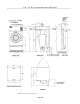
UNPACKING Unpacking/General Installation (All Dryers) Upon arrival of the equipment, any damage in shipment should be reported to the carrier immediately. Upon locating permanent location of a unit, care should be taken in movement and placement of equipment. See outline clearance diagrams for correct dimensions. Remove all packing material such as: tape, manuals, skid, etc. Leveling: Use spirit level on top of dryer. Adjust leveling bolts on dryer (see adjustable leveling bolts in maintenance section).
75 lb.
75 lb.
Specifications GENERAL SPECIFICATIONS NON-ENERGY SAVER MODELS Basket Load Capacity ............................. 75 lbs. (34.0 kg) dryweight Floor Space ............................................. 75” (191 cm) H x 38” (96 cm) W x 51” (130 cm) Deep Basket Size .............................................. 36” (91 cm) diameter x 36” Deep - 21 cu. ft. (0.63 M³) Exhaust Duct ........................................... 8” diameter (20.3 cm) Motor Sizes .............................................
Specifications STEAM HEATED MODEL Operating Steam Pressure ............................ 15 PSIG (low pressure) 100 PSIG (high pressure) Supply Connection to Solenoid ................... 3/4” (1.91 cm) Return Connection ....................................... 1” (2.54 cm) Steam Consumption ..................................... 214, 265 BTU/HR - 6.4 BHP 221 lbs. of condensate Drying Time (approximate) ......................... 75 lbs. dryweight - 70% water retention - 32 minutes Heat Capacity ...............
Motor List DOUBLE MOTOR MODELS Motor No. Voltage Hz. Phase MTR203 115/200/230 60 1 MTR212 200/230/460 60 MTR206 110/220 MTR104 Basket/Fan HP Amps RPM B 1 10.4/5.2 1725 3 B 1 3.8/1.9 1725 50 1 B 1 12/6 1425 240/415 50 3 B 1 3.1/1.8 1425 MTR104 220/380 50 3 B 3/4 2.6/1.5 1425 MTR104 220/380 60 3 B 3/4 2.4/1.4 1725 MTR104 200/346 50 3 B 3/4 2.6/1.5 1425 MTR101 575 60 3 B/F 1 1.7 1725 MTR209 115/208-230 60 1 F 1/3 5.2/2.
General Information & Grounding Instructions GENERAL INFORMATION The Cissell Dryer is so designed that when an operator opens the dryer door, the basket and exhaust fan stops. You can expect fast drying from a Cissell Laundry Dryer. Hot, dry air is properly and effectively moved through the basket and exhausted through a lint trap to the atmosphere. The Cissell Dryer comes equipped with an inclined, self-cleaning lint screen.
Grounding Instructions (Illustration) Page 15
Piping Recommendations PIPING RECOMMENDATIONS 1. Trap each dryer individually. Always keep the trap clean and in good working condition. 2. When dryer is on the end of a line of equipment, extend header at least 4 feet beyond dryer. Install globe valve, union, check valve and by-pass trap at end of line. If gravity return to boiler, omit trap. 3. Insulate steam supply and return line for safety of operator and safety while servicing dryer. 4. Keep dryer in good working condition.
Gas Piping GAS PIPING INSTALLATION Check gas rating plate for type of gas to equip the dryer. Check for altitude elevation of the dryer. Check utility for proper installation of gas supply line and gas pressure. NATURAL GAS ONLY Check the gas pressure inlet supply to dryer, 11” W.C. Pressure maximum. Check the manifold pressure 3.5” W.C. Pressure (Natural Gas). LP GAS ONLY 11” W.C. Pressure CAUTION Low gas pressure and intermittent gas will cause gas ignition problems.
Gas Piping Installation (Illustration) The dryer and it’s individual shutoff valve must be disconnected from the gas supply piping system during any pressure testing of that system at test pressures in excess of 1/2 PSIG. The dryer must be isolated from the gas supply piping system by closing it's individual manual shutoff valve during any pressure testing of the gas supply piping system at test pressures equal to or less than 1/2 PSIG.
Gas Service Installation Instructions GAS SERVICE INSTALLATION INSTRUCTIONS The size of the gas service pipe is dependant upon many variables, such as tees, lengths, etc. Specific pipe size should be obtained from the gas supplier. Refer to the “Gas Pipe Size” chart in this manual for general gas pipe size information.
Gas Pipe Size Chart TOTAL BTU/HR (for LP Gas correct total BTU/HR below by multiplying by .6) GAS PIPE SIZE FOR 1000 BTU (250 KCAL) NATURAL GAS AT 7” (17.8 CM) W.C. PRESSURE TOTAL KCAL In figuring total length of pipe, make allowance for tees and elbows. (50 ft.) (75 ft.) (100 ft.) (125 ft.) 15,24 m 22,86 m 30,48 m 38,1 m HOUR (25 ft.) 7,62 m (150 ft.
Steam Piping Installation Instructions STEAM PIPING INSTALLATION INSTRUCTIONS 1. Set and anchor dryer in position. Machine should be level to assure proper steam circulation. 2. To prevent condensate draining from headers to dryer, piping should have a minimum 12” above respective header. Do not make steam connection to header with a horizontal or downwardly facing tee or elbow. 3. Whenever possible, horizontal runs of steam lines must drain, by gravity, to respective steam header.
Steam Piping Installation (Illustration) Page 22
Dryer Installation With Multiple Exhaust For Exhaust Duct less than 14 feet and 2 elbows equivalent and less than 0.3 inches static pressure. DRYER EXHAUSTS Area of section “A-A” must be equal to the sum of dryer exhaust pipes entering multiple exhaust pipe. (See chart below.) MODELS: L28FD30, L28US30, L36FD30, L36UR30, L36CD36, L44FD42 No.
Dryer Installation with Multiple Exhaust DRYER INSTALLATION WITH MULTIPLE EXHAUST For Exhaust Duct more than 14 feet and 2 elbows equivalent and more than 0.3 inches static pressure. (See illustration on next page.) 1. 2. 3. 4. 5. 6. 7. Make-up air from outside building may enter enclosure from top or side walls. Area of opening should be equal to 4 to 6 times the sum of dryer duct areas. Provide 1 square foot (.1m²) for each 6 inches (15.24 cm) diameter; 2 square feet (.2m²) for each 8 inches (20.
Dryer Installation With Separate Exhaust (Preferred) DRYER INSTALLATION For ductwork less than 14 feet and 2 elbows equivalent and less than 0.3 WITH SEPARATE EXHAUST (PREFERRED) inches static pressure: NEVER exhaust the dryer into a chimney. NEVER install wire mesh screen over the exhaust or make-up air area. NEVER exhaust into a wall, ceiling, or concealed space. 1. 2. 3. 4. Make-Up Air opening from outside the building may enter the enclosure from the top or side walls.
Exhaust and Venting DRYER AIR FLOW INSTALLATION Nothing is more important than air flow for the proper operation of a clothes dryer. A dryer is a pump which draws make-up air from the out-of-doors, through the heater, through the clothes and then forces the air through the exhaust duct back to the out-of-doors. Just as in a fluid water pump, there must be a fluid air flow to the inlet of the dryer, if there is to be the proper fluid air flow out of the exhaust duct.
Rules for Safe Operation of Dryer RULES FOR SAFE OPERATION OF DRYER 1. 2. 3. 4. 5. 6. 7. 8. 9. Be sure your dryer is installed properly in accordance with the recommended instructions. CAUTION Be safe—shut main electrical power supply and gas supply off externally before attempting service. CAUTION Never use drycleaning solvents: gasoline, kerosene, or other flammable liquids in the dryer. Fire and explosion will occur. Never put fabrics treated with these liquids into the dryer.
Operating Instructions - Two Timer Model (Illustration) Page 28
Operating Instructions - Two Timer Model OPERATING INSTRUCTIONS TWO TIMER MODEL TEMPERATURE OPERATING INSTRUCTIONS - TWO TIMER MODEL Step 1. After loading the dryer with water washed clothes, close the loading door. Step 2. Turn the 60 minute drying (heat) timer to the desired time. The drying cycle light will be on. Step 3. Turn the 15 minute cooling (air) to the desired time. The cooling light will come on after the drying finishes. Step 4.
Automatic Computerized Drying Control DESCRIPTION DESCRIPTION The Automatic Computer Drying Control is used to manage the drying and cooling cycles of one clothes dryer. The operator has the flexibility to select either automatic or timed drying and either automatic or timed cooling. When automatic is selected, the drying cycle will be terminated when the clothes are dry. A dryness sensor "feels" the clothes and signals the control when they are dry.
Automatic Computerized Drying Control LED DISPLAY MESSAGES LED DISPLAY MESSAGES Display Condition “__0” Normal display between loads. Dryer is waiting for the next load. “012” Normal display during drying/ cooling cycle. Display shows “time used” when in automatic and “time remaining” when in timed mode. “012” (Flashing) The door has been opened. Close the door and press START to continue the cycle. “-S-” (Flashing) The dryer is in the Safety Tumble mode.
Automatic Computerized Drying Control OPERATION OF CONTROL PANEL (See drawing on page 33) ON 1. ON Turn the control on. If dryer is not used for 30 minutes, the power will turn off. Press “on” for power. OFF/STOP 2. OFF/STOP Turns the control off or stops the dryer during a cycle. START 3. START Starts the cycle or re-starts it off. COOLING TIME 4. COOLING TIME In timed mode, with this button held down, the set cooling time in minutes will be shown in the display.
Automatic Computerized Drying Control OPERATION OF CONTROL PANEL (continued) (See drawing on page 33) DRYING 8. DRYING Pressing this button changes the selection of automatic or timed drying, indicated by a light. COOLING 9. COOLING Pressing this button changes the selection of automatic or timed cooling, indicated by a light. In auto cooling mode, the cycle will end when the temperature falls below 135°F. REPEAT LAST CYCLE 10.
Automatic Computerized Drying Control Panel (Illustration) Page 34
Automatic Computerized Drying Control DETAILS OF CONTROL BOARD AND OPTIONS OPTIONS SWITCH SET #1 Switch ON OFF #8 #7 #6 #5 #4 #3 #2 #1 F/C SFTY-EN 6-Add Repeat S/E 2 Deg. 5 Deg. 10 Deg. 20 Deg. Deg F Enabled + 6 Min. Start + 2 Deg. + 5 Deg. + 10 Deg. + 20 Deg. Deg C Disabled 0 End 0 0 0 0 #8 F/C #7 SFTY-EN #6 6-Add #5 Repeat S/E #4 2 DEG. Adds 2 degrees to the differential temperature. #3 5 DEG. Adds 5 Degrees to the differential temperature. #2 10 DEG.
Automatic Computerized Drying Control DETAILS OF CONTROL BOARD AND OPTIONS OPTION SWITCH SET #2 These switches have no function. THERMISTOR CALIBRATION To verify the calibration of the thermistor circuit, proceed as follows: REVERSING DWELL 1. Disconnect the thermistor leads going to the circuit board. 2. Short the terminals at JP5 (thermistor calibration pins). 3. Press the “up arrow” and the “down arrow” keys to display the temperature. The temperature should read 158° F. 4.
Automatic Computerized Drying Control Board (Illustration) Page 37