Operation/Maintenance Mighty Mite and Super Laundry Presses Refer to Page 3 for Model Numbers SCR1529C SCR1529C Keep These Instructions for Future Reference. (If this machine changes ownership, this manual must accompany machine.) An LSG Company 831 South First Street, P.O. Box 32270 Louisville, KY 40232-2270 Phone: (502) 587-1292 Sales Fax: (502) 585-3625 Service/Parts Fax: (502) 681-1275 www.cissellmfg.com Part No.
Table of Contents Model Identification ........................................................................... 3 Safety Information.............................................................................. Explanation of Safety Messages........................................................... Important Safety Instructions ............................................................... 5 5 5 Introduction.........................................................................................
Notes 2 © Copyright, Alliance Laundry Systems LLC – DO NOT COPY or TRANSMIT AJ1032
Model Identification Information in this manual is applicable to the following models: LDBB (CMMBB) LDCC (CMMCCY) AJ1032 © Copyright, Alliance Laundry Systems LLC – DO NOT COPY or TRANSMIT 3
Notes 4 © Copyright, Alliance Laundry Systems LLC – DO NOT COPY or TRANSMIT AJ1032
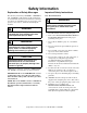
Safety Information Explanation of Safety Messages Important Safety Instructions Precautionary statements (“DANGER,” “WARNING,” and “CAUTION”), followed by specific instructions, are found in this manual and on machine decals. These precautions are intended for the personal safety of the operator, user, servicer, and those maintaining the machine. Save These Instructions DANGER Indicates an imminently hazardous situation that, if not avoided, will cause severe personal injury or death.
Safety Information Safety signs and labels are also placed on the press. Those signs and labels are limited messages. Where needed, further explanations are provided in the manual. These signs are to be inspected for readability and replaced when missing, damaged or unreadable. Refer to Maintenance section of this manual for inspections process. Refer to parts manual for ordering information. 12. Replace worn power cords and/or loose plugs. 13.
Introduction Nameplate Location Parts Ordering Information The nameplate is located at the right side of the unit. Always provide the machine’s serial number and model number when ordering parts or when seeking technical assistance. If literature or replacement parts are required, contact the source from which the machine was purchased or contact Cissell at (502) 587-1292 for the name and address of the nearest authorized parts distributor.
Notes 8 © Copyright, Alliance Laundry Systems LLC – DO NOT COPY or TRANSMIT AJ1032
Operation Operating Controls WARNING WARNING To avoid possible serious injury, BEFORE operating press, ALL personnel MUST be trained on safe operation. To avoid possible serious injury, ALWAYS read and become familiar with operating instructions before operating press. W338 W339 6 1 2 3 5 4 SCR95N Figure 2 Control 1. Right CLOSE pushbutton 2. Pressing TIME selector knob 3. Air Inlet Assembly including regulator, gauge, lubricator and downstream air relieving shut-off and lockout valve 4.
Operation NOTE: The following instructions will OPTIMIZE garment quality and prolong padding life. Pre-Operating Services 9. If pushbuttons do NOT perform as described in steps 3 through 8, do NOT operate press. Call a qualified service technician. 10. Slowly open steam supply and return shut-off valves to prevent water hammer in steam pipes. Allow 15 to 20 minutes for press to heat. Perform the following services daily before using press: 1. Check condition of buck padding.
Operation NOTE: If either pushbutton is released BEFORE pressing pressure is applied, head will return to a fully OPEN position. Pressing pressure will be applied for period of time set. When timer times out, head will automatically open. NOTE: Head can be opened at any time during timer controlled pressing by pressing OPEN pushbutton (Item 5, Figure 2). 6. Hang or fold pressed article as soon as possible to preserve finish.
Notes 12 © Copyright, Alliance Laundry Systems LLC – DO NOT COPY or TRANSMIT AJ1032
Maintenance NOTE: SHUTDOWNS due to unscheduled maintenance can be AVOIDED OR MINIMIZED by: • Performing periodic inspections as described, AND • Performing lubrication services at the time intervals specified in these instructions.
Maintenance Time Intervals Daily or as required Operation or Inspection Corrective Action Visually inspect sight glass in air line filter at inlet. (Refer to Item 4, Figure 4.) If moisture and oil are collecting in bowl, autodrain is not working. Clean, repair or replace auto-drain. Check buck padding. Clean padding. Replace padding if it is torn or brittle or has burn spots. Visually inspect press head for discoloration or Clean press head with a head surface cleaner as stickiness. needed.
Maintenance Cleaning Air Filter Cleaning Steam Strainer Air filter removes foreign matter and condensate from supply air as it passes through filter. Frequency at which the filter baffle plate and filter element should be cleaned depends upon amount of condensate and foreign matter in supply air. Condensate level should not rise above baffle. This is the sign of a faulty autodrain which would need to be cleaned, replaced or repaired. Strainer removes foreign matter from steam.
Maintenance Lubrication WARNING Lubrication points are illustrated in Figure 3. Lubrication points, time intervals, types and services are listed in Table 3. To avoid possible serious injury, ALWAYS close air supply line shut-off valve AND lock out air service BEFORE performing lubrication services. If complete details for lubrication services are not listed in Table 3, get detailed instructions from referenced paragraph.
Maintenance SYMBOLS A GREASE GUN OIL CAN A C B D B0159 INSPECTION AND LUBRICATION POINTS SCR102N Figure 3 AJ1032 © Copyright, Alliance Laundry Systems LLC – DO NOT COPY or TRANSMIT 17
Maintenance Adjusting Air Line Lubricator Flow Rate Filling Air Line Lubricator Air system oil lubricator should be adjusted so approximately one drop of oil every 20 machine cycles is metered into air system. The following steps outline the procedure for adjusting air system oil lubricator: When oil level falls below 1/4 full, refill bowl to 3/4 full (oil level approximately 1/2 inch [12.7 mm] from top) with ISO VG 32 grade oil. Refer to Table 3. NOTE: Do NOT overfill bowl.
Maintenance Quality Troubleshooting Problem “Crow’s feet” and wrinkles close to buttons, seams or folds Cause Solution Old or hard padding Check by placing a piece of cotton flannel on buck and pressing garment again. If quality improves, replace padding. Clogged air filter causing low air pressure Clean air filter. Low incoming air pressure Check the air pressure gauge at air inlet. It should be a constant 80 psi. Turn regulator knob to adjust if required.