JUNGLE MIST SYSTEM ANTI-DRIPTM Operating Instructions 110 VAC P/N 100071 230VAC P/N 100079
! ! ! ! Thank you for purchasing this Jungle Mist System Anti-DripTM As you will notice from the table of contents, the manual for your new pump is quite extensive. To guarantee perfect and successful work with this machine, please take time to read the manual carefully.
Contents 1 Equipment Supplied 3 2 Accessories and Parts 3 3 Safety information 4 4 Grounding Instructions 4 5 Receiving and Unpacking 5 5.1 5.2 Checking for Damage in Shipping Checking Inventory of Parts 6 Pump Start-up Procedure 6.1 6.2 Oil Reservoir Cap Replacement Pump Preparation 7 Hooking up the Pump 6 8 Mist Line Layout Strategies 8 9 Mist Line Assembly 8 9.1 9.2 9.3 9.4 9.5 9.
1. Equipment Supplied ! Jungle Mist System Anti-DripTM (110V P/N 100071; 230V P/N 100079 (Please see section 5.2 for a complete checklist.) 2. Accessories and Parts ! Universal DMX Relay – 3 pin XLR, Heavy Duty (P/N 250042) ! Nozzle cleaner (8oz bottle P/N 600741; 1-gal bottle P/N 600742) ! Tubing (50ft roll P/N 600730; 100ft roll P/N 600731) ! Nozzles (0.008” nozzle P/N 600723; 0.
600766 600768 600770 600771 600780 600781 600782 Set of 4 Wheels 2X Push-Connector Auto Drain-down (anti-freeze) Pump Water Seal Kit 6 Valve Rebuild Kit 5 head nozzle .008 w/ anti-drip adapter 5 head nozzle .012 w/ anti-drip adapter Push-con Union 3. Safety Information 3.1 • • • 3.2 • • • • • • WARNING: Read through the entire instructions before attempting installation. Risk of electrical shock - This pump is supplied with a grounding conductor.
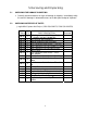
5. Receiving and Unpacking 5.1 CHECKING FOR DAMAGE IN SHIPPING • 5.2 Carefully examine contents for signs of damage in shipping. Immediately notify the carrier if damage is detected that was not visible upon receipt of shipment. CHECKING INVENTORY OF PARTS Jungle Mist System Anti-DripTM (110V P/N 100071; 230V P/N 100079) CITC ITEM # QTY.
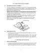
6. Pump Start-up Procedure 6.1 OIL RESERVOIR CAP REPLACEMENT • • • • 6.2 The unit is shipped with a non-vented oil reservoir cap. The unit has to be sealed in order to prevent leakage of the oil during shipping. In order to operate the unit, YOU MUST REPLACE THE NON-VENTED CAP WITH THE ENCLOSED VENTED OIL RESERVOIR CAP (BREATHER CAP). Operation of the machine without removing the plug and replacing it with the breather cap WILL VOID THE WARRANTY.
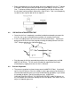
7.2 WATER SUPPLY • 7.3 Insure that the water source being used can supply enough water for the demand of the pump. Use a minimum ¾” hose (19 mm). This unit does not use suction to pull from a water source. Provide at least 40 PSI (2.8 bar) of clean water WATER FILTER INSTALLATION • NOTE! Use factory-supplied water filter in water supply to the pump. Contaminants in water can damage pump and plug nozzles if filter is not used! Pressure Adjust Pressure Gauge OUT IN Drain Bucket • • • 7.
8. Mist Line Layout Strategies 8.1 LIGHT, MEDIUM OR HEAVY HAZE • • • • 8.2 INDOOR FOG CURTAINS • 8.3 Light – Use 35 fine nozzles (0.008”) Medium – Use 20 fine, 10 heavy nozzles (0.012”), alternating every 2 or 3 fine nozzles with a heavy nozzle for a total of 30 nozzles. Heavy Haze Mist – Use 25 heavy nozzles (0.012”) for thickest mist in low humidity areas. Note: the driest mist will be the light mist. Order heavy nozzles for medium or heavy haze (additional).
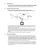
• 9.2 Begin assembling the mist line by taking one of the supplied Push-Con “T” Nozzle assemblies with the precut tubing and push the nylon tubing in to the next PushCon “T” with precut tubing, being sure to completely push into the fittings. Hold the ring from moving and push again with a slight ¼ twist. Feel it seat completely. Let loose of the ring then pull to test for tightness.
9.4 Checking for Leaks • • 9.5 Check for leaks that may have occurred due to the tubing not being inserted beyond the o-ring seal. In case of a leak, turn the pump off and remove the leaking fitting. Then insert the tubing back into the fitting making sure the tubing inserts beyond the o-ring. When removing the Push-Con fitting, use a 3/8” openend wrench against the ring, holding the connector with your thumb. If you still have leaks, remove the tubing and touch the edge of the tubing for sharpness.
• Push-Con “T” fitting on the mist line. If any elbows are required in your feed or mist line, connect them in the same manner as the “T” fittings. Note on permanent installations: when connecting pump to stainless or copper tubing install a flexible discharge hose between pump and tubing to reduce vibration to piping. 10. Maintenance procedures 10.1 SYSTEM PRESSURE • 10.2 Your pump includes a 2000 PSI (138 bar) high pressure glycerine-filled gauge and an adjustable unloader valve.
11. Troubleshooting 11.1 Low Pressure • Check number of nozzles – too many will lower pressure and cause the pump to work too hard. • Leak in line on discharge side: inspect all nozzles, lines and fittings for leaks. • Insufficient supply of water: increase flow of supply line and check water filter. • Fouled or dirty inlet or discharge valves: clean inlet and discharge valve assemblies. • Worn inlet, discharge valve blocked or dirty: replace worn valves, valve seats and/or discharge hose.
12 . Technical Data Jungle Mist System Anti-DripTM 110VAC P/N 100071; 230V P/N 100079 Case Dimensions 17" x 14" x 9.5" (43.2cm x 34.9cm x 24.1cm) Overall Dimensions 22” x 13.75” x 12” (with hose connections) (55.9cm x 34.9cm x 30.5cm) Weight 90 lbs (40.9 kg) Shipping Weight 95 lbs (43.2 kg) Shipping Dimensions 24” x 17” x 20” (61cm x 43.2cm x 50.
13. Limited Warranty Conditions Jungle Mist System Anti-DripTM 1. Subject to the following conditions we will repair any defect or fault in the unit if it is caused by a proven factory fault and has been advised immediately after appearance and within 30 days of delivery to the end user. Insignificant deviations of the regular product quality does not guarantee replacement rights, nor do faults or defects caused by water, by generally abnormal environment conditions or Force Majeure. 2.
If you should send the unit for service, do not forget to replace the vented oil cap with the non-vented cap used for shipping the unit. Also drain water from system. Obtain your RMA # by calling CITC. Payment arrangements for repair must be made before receiving RMA # in case unit is not covered under Limited Warranty. Send unit to: CITC RMA # XXXXXXX 2100 196th Street SW Suite #138 Lynnwood, WA 98036 Tel: (888) 786-CITC or (425) 776-4950 Fax: (425) 776-5129 Website: www.citcfx.com E-mail: info@citcfx.