iDP-3540/41 User’s Manual CITIZEN User’s Manual MINI DOT MATRIX PRINTER MODEL iDP-3540/3541 Japan CBM Corporation Information Systems Div.
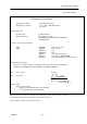
iDP-3540/41 User’s Manual 1995.09.04(10-DCL)1 Declaration of Conformity Manufacturer's Name : Manufacturer's Address : Japan CBM Corporation : 1-1-7, Okubo, Shinjuku-ku, Tokyo 169, Japan Declare the Product Product Name Model Number (s) Dot Matrix Printer iDP-3540, 3541 Series (iDP3540R, iDP3540P, iDP3541R, iDP3541P) (S.NO.
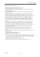
iDP-3540/41 User’s Manual IMPORTANT SAFETY INSTRUCTIONS * Read all of these instructions and save them for later reference. * Follow all warnings and instructions marked on the product. * Unplug this product from the wall outlet before cleaning. Do not use liquid or aerosol cleaners. Use a damp cloth for cleaning. * Do not use this product near water. * Do not place this product on an unstable cart, stand of table. The product may fall, causing serious damage to the product.
iDP-3540/41 User’s Manual CONTENTS 1. Introduction ...................................................................................................................................................... 6 1-1. Features ..................................................................................................................................................... 6 1-2. Accessories.............................................................................................................................
iDP-3540/41 User’s Manual 11-3. Slide Switch Setting (Serial interface specifications only).................................................................... 32 11-4. Dip-Switch Location ............................................................................................................................. 32 12. Print Control Functions................................................................................................................................. 33 12-1. Control Codes...............
iDP-3540/41 User’s Manual 1. Introduction The iDP3540 is a dot impact printer which can be utilized for a wide range of applications, such as data communications terminals, P.O.S. terminals and kitchen printers. High speed performance is made possible by a bi-directional printing system and, since this printer is compact, lightweight and equipped with an abundance of functions, they can be easily employed for a variety of different tasks.
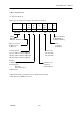
iDP-3540/41 User’s Manual 2. Basic Specifications 2-1. Type classifications Printer types are classified according to the system shown below.
iDP-3540/41 User’s Manual 3. Specifications 3-1. General Specifications Item iDP3540F iDP3540P 1 Print Method Bidirectional serial dot impact method 2 Character 7 × 7 dots (incl. Half-dot) composition Character Printer DP-610: 23 columns 230 dots/line 3 number per DP-612: 28 columns 280 dots/line line DP-614: 40 columns 360 dots/line DP-617G: 40 columns 400 dots/line Printer DP-610: 23 columns approx 4.0 line/sec. 4 Print speed DP-612: 28 columns approx 3.0 line/sec. DP-614: 40 columns approx 3.0 line/sec.
iDP-3540/41 User’s Manual *1 Input buffer can be selected by setting the DIP switch. *2 However, when the input buffer is set for two lines, back-up of graphic data is not possible. *3 Single color cassette ribbon is available as option.
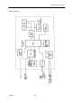
iDP-3540/41 User’s Manual 4.
iDP-3540/41 User’s Manual 5. External Appearance and parts Description 5-1.
iDP-3540/41 User’s Manual 5-2.
iDP-3540/41 User’s Manual 5-3. Parts Descriptions (1) Power Cord (2) Power Switch (3) Power Lamp Insert the plug end into an electric outlet. Power is supplied to the printer by turning this switch on. This lights up when the power switch is “ON” and goes out when turning “OFF”. (4) SEL / ALARM Lamp This lights up when the printer is in SELECT state (ON-LINE) and goes out when in DESELECT state (OFFLINE). The printer can print out the data only when this lamp is on.
iDP-3540/41 User’s Manual 6. Preparation 6-1. Inserting / Removing the Printer Cover Inserting and removing the printer cover as shown in Fig. 1, 2. Fig. 1 Fig. 2 6-2. Opening and Closing the Cutter Unit (iDP3541) 1) To open the unit, grasp two levers and lift upward. 2) When closing the unit, press downward until it completely lock place. Fig.
iDP-3540/41 User’s Manual 6-3. The Ribbon Cassette Installation To insert the ribbon, disconnect the power source beforehand. If the printer has been printing for many hours, be careful not to touch the printer head as it might be hot. 1) Remove the printer cover 2) While inserting the ribbon into the space between the print head and the ribbon guide, press the cassette into the holder unit it clicks into place. (Ref. to Fig.
iDP-3540/41 User’s Manual 6-4. Loading and Changing the Paper 6-4-1. Using Paper Roll (iDP3540F, 3541) 1) 2) 3) 4) Cut the paper in right angle to its longitudinal center line as shown in Fig. 7. Insert the paper into insertion inlet on the rear side of printer. Turn on the power switch and feed the paper by pushing the LF switch. When the printing paper comes out of the clearance (paper cutter part) on the printer cover, fix the paper by means of paper holder, then set in on the main unit.
iDP-3540/41 User’s Manual 6-4-2. Using Fan-Fold Paper (iDP3540P) 1) Remove the printer cover 2) Set the imprint face of the paper downward and put into the paper entrance. 3) If necessary to adjust the sprocket-wheel’s position, free the wheels using the lever on both sides. Slide them to the appropriate position, and lock them back.
iDP-3540/41 User’s Manual 6-6. Self Test Printing Your printer has a built in self print function for purpose of checking print operation without the need for any other external device. Procedures for Actuating the Print Function 1) Be sure that a paper roll is properly loaded. 2) Confirm that the ribbon cassette is properly installed and turn the power switch off. 3) Turn the power switch ON while pressing the LF switch, and release the LF switch after the self test operation has begun.
iDP-3540/41 User’s Manual 8. Parallel Interface 8-1. Specifications a) Data Input system b) Control Signals c) Compatible Connector : 8 bit parallel (DATA 1~8) : ACK, BUSY, STB, FAULT, PE, RESET : Printer side : 57LE-40360 (AMPHENOL or equivalent) : Cable side : 57-30360 (AMPHENOL or equivalent) 8-2. Connector Pin Assignment Pin No.
iDP-3540/41 User’s Manual 8-3. Description of Input / Output Signals 8-3-1. Input / Output Signals a) Input / Output Signals *DATA *STB *RESET : 8 bit parallel signal. (Positive logic) : A strobe signal for reading in 8 bit data. (Negative logic) : A signal which resets the entire printer. (Negative logic, 1 ms or more) b) Output Signals (From Printer) *ACK *BUSY *FAULT : This is a pulse signal for requesting 8 bit data, issued at the end of a BUSY signal.
iDP-3540/41 User’s Manual 8-3-2. Electrical Characteristics a) Input Signal Level All input signals are TTL level. “HIGH” level …. 2.0V Min. “LOW” Level …. 0.8V Max. b) Output Signal Level “HIGH” level …. 2.4V Min. “LOW” Level …. 0.4V Max. c) Input / Output Conditions All of the input signals are pulled up by 3.3K ohms. [Printer Side] 7406 or equivalent All of the output signals are pulled up by 3.3K ohms.
iDP-3540/41 User’s Manual 8-3-3. Timing Chart a) Data Input and Print Timing 8-3-4. Data Receiving Control Your printer is able to receive data sent from the host side when the BUSY signal is LOW, but unable to receive when the BUSY signal is HIGH. 8-3-5. Buffering 1) N Type Your printer is provided with a two line input buffer. 2) B Type Your printer is provided with a 7K byte input buffer. This makes possible a large amount of data buffering.
iDP-3540/41 User’s Manual 9. Serial Interface 9-1.
iDP-3540/41 User’s Manual 9-2.
iDP-3540/41 User’s Manual 9-3. Description of Input / Output Signals 9-3-1. Input / Output Signals a) RD: This is the serial signal for received data. When framing, overrun or parity errors occur, the data is converted into (7FH). b) DTR: Please write in data or commands when this signal is in a “ready” state. If written in when in a BUSY state, an overrun error will occur and the data will be ignored. Data can be written into the input buffer even during printing.
iDP-3540/41 User’s Manual 9-3-2. Data Composition [1] Start bit [2] Data bits (and parity bit) [3] Stop bit (1 bit or more) 1) Start bit 1/2 bit past the line dropping from MARK to SPACE, a status reading is taken again. If the reading is SPACE, a start bit is recognized, but if it is MARK, it is not taken as a start bit. This is not regarded as an error, but the search for the start bit is performed once again.
iDP-3540/41 User’s Manual 9-3-4. Data Receiving Control When the BUSY signal is LOW, your printer receives data from the host side, but when this signal is HIGH, it cannot receive data. 9-3-5. Buffering Data transfer to the input buffer is controlled by the DTR and TD signals. Please refer to 9-3-1 b) for the DTR signal and 9-3-1 f) for the TD signal.
iDP-3540/41 User’s Manual 9-3-6.
iDP-3540/41 User’s Manual c) Current Loop Circuit Input (RD) [Printer Side] [Host Side] Mark = Current ON Space = Current OFF Output (DTR, TD) [Printer Side] *DTR *TD CITIZEN [Host Side] Current ON : READY Current OFF : BUSY Mark : Current ON Space : Current OFF 29/48
iDP-3540/41 User’s Manual 10. External Output [Printer Side] [Host Side] Remarks : The solenoid for drawer should be more than 36 Ohms.
iDP-3540/41 User’s Manual 11. Function Selection In order to meet the widest possible range of needs, various conditions can be selected by setting the DIP switches. 11-1. Setting DIP Switch DS1 No.
iDP-3540/41 User’s Manual 2) RS-422A type only No. Function 1 2 3 4 5 6 7 8 2 2 2 bps No. 5 6 7 8 110 Printer address OFF ON L L L H H H Baud rate setting 150 300 600 Refer to the table below Factory Setting OFF OFF OFF OFF OFF ON ON OFF 1200 2400 4800 9600 OFF ON OFF ON OFF ON OFF ON OFF OFF ON ON OFF OFF ON ON OFF OFF OFF OFF ON ON ON ON OFF OFF OFF OFF OFF OFF OFF OFF 11-3.
iDP-3540/41 User’s Manual 12. Print Control Functions 12-1. Control Codes Function code FF + n SO SI LF CR DC1 DC2 DC3 CAN ESC + P + 0 ESC + P + 1 ESC + - + n ESC + * + n1 + n2 ESC + 1 ESC + 2 ESC + C + n ESC + f + 1 ESC + N + n ESC + O RS SUB FS ESC + BEL + N1 + N2 BEL CITIZEN Hex.
iDP-3540/41 User’s Manual 12-2. Input Data Formats 12-2-1. Paper feed command for “n” lines 1st byte D8 0 D1 0 0 0 0 0 0 0 FF(0C)H 2nd byte D8 0 D1 N7 N6 N5 N4 N3 N2 N1 n(N7 N1) (Binary digits) When the number of lines to be fed (2nd byte) is written-in following the paper feed command (1st byte), the paper will be fed by the number of lines specified. The number of lines to be fed can be specified from n = 1 to 127. If “0” is specified, paper feed will not be carried out.
iDP-3540/41 User’s Manual 12-2-4. Paper feed command D8 0 D1 0 0 0 1 0 1 0 LF(0A)H When there is data in the internal print buffer, line feed will be carried out after printing is completed. When the buffer is empty, line feed only will be carried out. 12-2-5. Print command D8 0 D1 0 0 0 1 1 0 1 CR(0D)H By means of this command, printing will be carried out. In order to accommodate the print data output formats of various computers, the CR function is selectable.
iDP-3540/41 User’s Manual 12-2-8. Initial Set Command D8 0 D1 0 0 1 0 0 0 1 DC1(11)H The controller is initialized by this command and the following conditions are established. *Internal input buffer cleared * Normal character mode selected * Black color print mode selected * Skip designation cancelled * Page length set to 66 lines * Line feed pitch set to 2/9 inch (graphic type only) 12-2-9.
iDP-3540/41 User’s Manual 12-2-11. Underline Command 1st byte D8 D1 0 0 0 1 1 0 1 1 ESC (1B) H 2nd byte D8 D1 0 0 1 0 1 1 0 1 - (2D) H rd 3 byte D8 0 D1 0 0 0 0 0 0 N1 n (Binary digits) When n = 1, the underline mode is set, and when n = 0, it is cancelled. 12-2-12.
iDP-3540/41 User’s Manual Bit image mode printing is performed by this command. (n2 is the equotient when divided by 256, and n1 is the remainder.) When data is received only for numbers specified by n1 and n2, printing and line feed are carried out automatically, and the bit image mode is cancelled. However, since “half-dots” are being used, the next corresponding pin cannot print at the same time. Further, the maximum value of n1 and n2 is the number contained in one line, and this cannot be exceeded.
iDP-3540/41 User’s Manual 12-2-15. Page Length Set Command 1st byte D8 D1 0 0 0 1 1 0 1 1 ESC (1B) H 2nd byte D8 D1 0 1 0 0 0 0 1 1 C(43)H rd 3 byte D8 0 D1 N7 N6 N5 N4 N3 N2 N1 n (Binary digits) The length of one page is set to “n” lines by this command. (1£n£127) 12-2-16.
iDP-3540/41 User’s Manual This command feeds the paper (skips) “n” lines without any printing. However, this cannot exceed the length of one page. (1£n£126) 12-2-18. Skip Perforation Cancel Command 1st byte D8 D1 0 0 0 1 1 0 1 1 ESC (1B) H 2nd byte D8 D1 0 1 0 0 1 1 1 1 N(4F)H This command cancels the skip perforation function. 12-2-19.
iDP-3540/41 User’s Manual 12-2-21. Drive Pulse Duration Setting Command For the First Drawer 1st byte D8 D1 0 0 0 1 1 0 1 1 ESC (1B) H 2nd byte D8 D1 0 0 0 0 0 1 1 1 BEL(07)H rd 3 byte D8 D1 n1 (DEFAULT=20) 4th byte D8 D1 n2 (DEFAULT=20) This command adjusts the drive pulse duration for the first drawer.
iDP-3540/41 User’s Manual 12-2-22. First Drawer Drive Command D8 0 D1 0 0 0 0 1 1 1 BEL (07) H This command generates a drive pulse for first drawer based on the condition of drive pulse duration setting command. This command is stored in the buffer and is performed when it is received from buffered queue. 12-2-23.
iDP-3540/41 User’s Manual 13. Initial Setting Followings are automatically set after Power-on. (1) Printer head returns to its start position. (2) SELECT (ON-LINE) or DESELECT (OFF-LINE) status may be chosen by the Dip Switches for Pre-Setting. (3) Print buffer is cleared. (4) Standard character mode is set. (5) 66 lines per page is set. (6) The first line set at the present line. (7) Designation of Red printing is cleared. (8) For 7 bit data, character code SI is applied.
iDP-3540/41 User’s Manual 14. Maintenance 14-1 Maintenance Procedures It is recommended that users perform periodic cleaning of their printer. 14-1-1 Exterior The exterior case of the printer can be cleaned with alcohol. Care should be taken to keep water from reaching the electronic parts and the printing mechanism. 14-1-2 Interior There is no particular requirement, however, when the printer case is opened to change setting etc.
iDP-3540/41 User’s Manual 16. Character Code Tables International Character Codes The following codes are set as space characters.
iDP-3540/41 User’s Manual Individual Country Character Codes CITIZEN 46/48
iDP-3540/41 User’s Manual 17. External Dimensions 17-1.
iDP-3540/41 User’s Manual 17-2.