Command Reference MODEL : CT-S280 CT-S300 CT-S2000 CT-S4000 BD2-2220 CT-S310 PMU2XXX Revision 0.
REVISON Rev No. Date Comment 0.00 2006/9/26 Newly isuued 0.01 2006/11/22 Add program sample for FS p and FS q 0.02 2007/2/26 Revised page 153,155,159,169,205-207 0.03 2007/5/21 Supported CT-S310 0.04 2007/8/29 Supported PMU2XXX CITIZEN is a registered trade mark of CITIZEN HOLDINGS CO., LTD., Japan. CITIZEN es una marca registrada de CITIZEN HOLDINGS CO., LTD., Japón.
TABLE OF CONTENTS TABLE OF CONTENTS................................................................................... 3 1. OUTLINE................................................................................................... 9 1.1 OPERATION MODE .........................................................................................................9 1.2 CHARACTER SET .............................................................................................................9 1.3 CONTROL COMMANDS ...
ESC t n...........................................................................................................................................51 ESC { n ..........................................................................................................................................52 ESC ~ J n (Valid in CBM-270-Compatible Mode)......................................................................53 ESC ~ J n (Valid in CBM1000-Compatible Mode) ....................................................
2.2.11 Cutter Commands....................................................................................................... 100 ESC i ............................................................................................................................................100 ESC m ..........................................................................................................................................101 GS V m ・・・ (1) .....................................................................
2.2.15 Black Mark Control Commands ................................................................................. 143 GS FF ...........................................................................................................................................143 GS < ............................................................................................................................................143 GS A m n.....................................................................................
fn=82: Function 82 Sending the size of 2-dimensional code data in 2-dimensional code data storage area.........................................................................................................................................................214 fn=65: Function 165 Specifying QRCode model ..................................................................................215 fn=67: Function 167 Sets the module width of QRCode ......................................................................
4. MEMORY SWITCH................................................................................ 265 4.1 MEMORY SWITCHES .................................................................................................. 265 4.1.1 CT-S280.......................................................................................................................... 265 4.1.2 CT-S300.......................................................................................................................... 266 4.1.
1. OUTLINE 1.1 Operation Mode Our printer has ESC/POSTM as control commands. 1.2 Character Set All print data sent from the host computer to the printer are automatically converted to one-byte alphanumeric or katakana characters (ANK) or two-byte Kanji corresponding to the characters and symbols. NOTE: For the contents of character set, refer to Character Code Table of this document. 1.3 Control Commands 1.3.
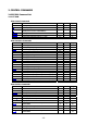
2. CONTROL COMMANDS 2.1 ESC/POS Command List 2.1.
Line Feed Span Commands Command ESC 2 ESC 3 Function Specifying initial line feed rate Setting line feed rate of minimum pitch MODE S・P S・P GS P MODE S・P S・P S・P S GS P Page 76 77 78 79 MODE S・P S・P S・P S・P GS P Page 81 89 90 93 MODE GS P Page ○ Page 74 75 Bit Image Commands Command ESC * GS * GS / GS v 0 Function Specifying the bit image mode Defining the download bit image Printing the downloaded bit image Printing of raster bit image Status Commands Command DLE EOT ESC v GS a GS r Funct
Kanji Control Commands Command FS ! FS & FS FS . FS 2 FS C FS S FS W FS ( A Function Collectively setting Kanji print mode Setting Kanji mode Setting/Canceling Kanji underline Canceling Kanji mode Defining external character Selecting Kanji code system Setting Kanji space amount Setting/Canceling four times enlargement of Kanji Setting font attribute of Kanji MODE S・P S・P S・P S・P S・P S・P S・P S・P S・P GS P MODE S S S S GS P Page 153 200 204 207 MODE S・P S・P S・P S・P S P S S・P S・P GS P Page 219 221 222
2.1.
Line Feed Span Commands Command ESC 2 ESC 3 Function Specifying initial line feed rate Setting line feed rate of minimum pitch MODE S・P S・P GS P MODE S・P S・P S・P S GS P Page 76 77 78 79 MODE S・P S・P S・P GS P Page 81 90 93 MODE GS P Page ○ Page 74 75 Bit Image Commands Command ESC * GS * GS / GS v 0 Function Specifying the bit image mode Defining the download bit image Printing the downloaded bit image Printing of raster bit image Status Commands Command DLE EOT GS a GS r Function Sending s
Kanji Control Commands Command FS ! FS & FS FS . FS 2 FS C FS S FS W FS ( A Function Collectively setting Kanji print mode Setting Kanji mode Setting/Canceling Kanji underline Canceling Kanji mode Defining external character Selecting Kanji code system Setting Kanji space amount Setting/Canceling four times enlargement of Kanji Setting font attribute of Kanji MODE S・P S・P S・P S・P S・P S・P S・P S・P S・P GS P MODE S・P S・P S・P S・P S・P S・P S・P S・P GS P Page 143 143 144 145 146 147 148 149 MODE S S S S S GS
2.1.
Line Feed Span Commands Command ESC 2 ESC 3 Function Specifying initial line feed rate Setting line feed rate of minimum pitch MODE S・P S・P GS P MODE S・P S・P S・P S GS P Page 76 77 78 79 MODE S・P GS P Page 81 ○ Page 74 75 Bit Image Commands Command ESC * GS * GS / GS v 0 Function Specifying the bit image mode Defining the download bit image Printing the downloaded bit image Printing of raster bit image Status Commands Command DLE EOT ESC u ESC v GS a GS r Function Sending status in real-time T
Commands for Non-volatile Memory Command GS ( C GS ( L GS 8 L GS g 0 GS g 2 FS p FS q Function Editing user NV memory MODE S GS P Page 112 Specifying graphics data S 118 Initializing maintenance counter Sending maintenance counter Printing the download NV bit images Defining the download NV bit image S S S S 126 127 128 130 Kanji Control Commands Command FS ! FS & FS FS . FS 2 FS C FS S FS W FS ( A Function Collectively setting Kanji print mode Setting Kanji mode Setting/Canceling Kanji underlin
Other Commands Command DLE ENQ DLE DC4 ESC = ESC @ ESC L ESC S ESC p GS ( A GS I GS P ESC RS Function Real-time request to printer Outputting specified pulse in real-time/Buffer clear Data input control Initializing the printer Selecting PAGE MODE Selecting STANDARD MODE Generating the specified pulses Execution of test printing Sending the printer ID Specifying the basic calculation pitch Sound buzzer In the Mode column: S = STANDARD MODE, P = PAGE MODE O = shows the command affected by GS P.
2.1.
Bit Image Commands Command ESC * GS * GS / GS v 0 Function Specifying the bit image mode Defining the download bit image Printing the downloaded bit image Printing of raster bit image MODE S・P S・P S・P S GS P Page 76 77 78 79 MODE S・P S・P S・P GS P Page 81 90 93 MODE GS P Page Status Commands Command DLE EOT GS a GS r Function Sending status in real-time Enabling/disabling ASB (Automatic Status Back) Sending status Paper Detecting Commands Command ESC c 3 ESC c 4 Function Selecting the Paper Sen
Kanji Control Commands Command FS ! FS & FS FS . FS 2 FS C FS S FS W FS ( A Function Collectively setting Kanji print mode Setting Kanji mode Setting/Canceling Kanji underline Canceling Kanji mode Defining external character Selecting Kanji code system Setting Kanji space amount Setting/Canceling four times enlargement of Kanji Setting font attribute of Kanji MODE S・P S・P S・P S・P S・P S・P S・P S・P S・P GS P MODE S S S GS P Page 153 200 204 MODE S・P S・P S・P S・P S P S S・P S・P GS P Page 219 221 222 223 2
2.1.
Bit Image Commands Command ESC * GS * GS / GS v 0 Function Specifying the bit image mode Defining the download bit image Printing the downloaded bit image Printing of raster bit image MODE S・P S・P S・P S GS P Page 76 77 78 79 MODE S・P S・P S・P GS P Page 81 90 93 MODE GS P Page Status Commands Command DLE EOT GS a GS r Function Sending status in real-time Enabling/disabling ASB (Automatic Status Back) Sending status Paper Detecting Commands Command ESC c 3 ESC c 4 Function Selecting the Paper Sen
Kanji Control Commands Command FS ! FS & FS FS . FS 2 FS C FS S FS W FS ( A Function Collectively setting Kanji print mode Setting Kanji mode Setting/Canceling Kanji underline Canceling Kanji mode Defining external character Selecting Kanji code system Setting Kanji space amount Setting/Canceling four times enlargement of Kanji Setting font attribute of Kanji MODE S・P S・P S・P S・P S・P S・P S・P S・P S・P GS P MODE S・P GS P Page 143 MODE S S S GS P Page 153 200 204 MODE S・P S・P S・P S・P S P S S・P S・P GS
2.2 Command Details 2.2.1 Description of Items XXXX support model [Function] [Code] [Range] [Outline] The name of a command. The string of codes comprising the command is represented by < >H for hexadecimal numbers, < >B for binary numbers, and < > for decimal numbers, [ ] k denotes the number of repetition of “k” times. Indicates the values (setting range) of arguments of the command.
2.2.2 Print Control Commands LF support model CT-S280 PMU2XXX CT-S300 CT-S2000 CT-S4000 BD2-2220 CT-S310 [Function] Printing and paper feed [Code] <0A>H [Outline] [The specification which is common to the model] Prints data inside the print buffer and feeds paper based on the line feed amount having been set. [Caution] After this command is executed, the beginning of the line is taken as the start position for the next point.
CR support model CT-S280 PMU2XXX CT-S300 CT-S2000 CT-S4000 [Function] Back to printing [Code] <0D>H [Outline] [The specification which is common to the model] (1) When memory switch 1-5 is OFF: This command is ignored. (2) When memory switch 1-5 is ON: The same operation as LF is executed.
FF (At selection of PAGE MODE) support model CT-S280 PMU2XXX CT-S300 CT-S2000 CT-S4000 BD2-2220 CT-S310 [Function] Printing in PAGE MODE and returning to STANDARD MODE (at the selection of PAGE MODE) [Code] <0C>H [Outline] [The specification which is common to the model] Executes a batch printout of the data mapped in the entire print area, and then returns to STANDARD MODE. [Caution] • All mapped data is erased after printout. • The print area set up by ESC W is initialized.
ESC FF support model CT-S280 PMU2XXX CT-S300 CT-S2000 CT-S4000 BD2-2220 CT-S310 [Function] Printing data in PAGE MODE [Code] <1B>H<0C>H [Outline] [The specification which is common to the model] Executes a batch printout of the data mapped in the entire print area in PAGE MODE. [Caution] • This command is only effective when PAGE MODE is selected. • Mapped data, as well as the ESC T and ESC W settings, and the character mapping position are held even after printing. [See Also] Appendix 5.
ESC J n support model CT-S280 PMU2XXX CT-S300 CT-S2000 CT-S4000 BD2-2220 CT-S310 [Function] Printing and feeding paper in minimum pitch [Code] <1B>H<4A>H [Range] 0≦n≦255 [Outline] [The specification which is common to the model] Prints the data held in the print buffer and feeds paper by [n×basic calculation pitch] inches. [Caution] • After this command is executed, the beginning of the line is taken as the start position for the next print.
ESC d n support model CT-S280 PMU2XXX CT-S300 CT-S2000 CT-S4000 BD2-2220 CT-S310 [Function] Printing and feeding the paper by “n” lines [Code] <1B>H<64>H [Range] 0≦n≦255 [Outline] [The specification which is common to the model] Prints data in the print buffer and feeds paper by “n” lines. Specified lines do not remain. [Caution] • After this command is executed, the beginning of the line is taken as the start position for the next print.
2.2.3 Print Character Commands CAN support model CT-S280 PMU2XXX CT-S300 CT-S2000 CT-S4000 BD2-2220 CT-S310 [Function] Canceling print data in PAGE MODE [Code] <18>H [Outline] [The specification which is common to the model] Erases all data contained in the currently effective print area in PAGE MODE. [Caution] • This command is only effective when PAGE MODE is selected.
ESC SP n support model [Function] [Code] CT-S280 PMU2XXX CT-S300 CT-S2000 CT-S4000 BD2-2220 CT-S310 Setting the right spacing of the character <1B>H<20>H [Range] 0≦n≦255 [Outline] [The specification which is common to the model] Sets the right spacing of character to [n×basic calculation pitch] inches. [Caution] • If the horizontal magnification of character is 2 or more, the right spacing increases with the magnification. • Does not affect Kanji.
ESC ! n CT-S280 PMU2XXX support model CT-S300 CT-S2000 CT-S4000 [Function] Collectively specifying the printing mode [Code] <1B>H<21>H [Range] 0≦n≦255 [Outline] [The specification which is common to the model] Printing mode is assigned.
[Caution] • With double height and double width being specified simultaneously, quadruple characters are created. • An underline is attached to the full character width, which, however, is not attached to the part having been skipped by the horizontal tab (HT). Neither is it attached to 90°-right-turned characters. • The underline width is as specified by the ESC – command. (The default setting is 1 dot width.
ESC % n CT-S280 PMU2XXX support model CT-S300 CT-S2000 CT-S4000 [Function] Specifying/canceling download character set [Code] <1B>H<25>H [Range] 0≦n≦255 [Outline] [The specification which is common to the model] Specifying/canceling download characters. • “n” is valid only for the lowest bit (n0).
ESC & s n m [ a [p] s x a ] m-n+1 support model CT-S280 PMU2XXX CT-S300 CT-S2000 CT-S4000 BD2-2220 CT-S310 [Function] Defining the download characters [Code] <1B>H<26>HHHH[HH・・・]m-n+1 [Range] s=3(Font A, B) s=2(FontC) 32≦n≦m≦127 0≦a≦12(Font A) 0≦a≦9 (Font B) 0≦a≦8 (Font C) 0≦p1・・ps×a≦255 [Outline] [The specification which is common to the model] Defines the font of download characters of alphanumeric characters.
[Example] 12dot 24dot p1 p4 p34 p2 p5 p35 p3 p6 p36 Font A MSB LSB Create each data bit by setting “1” for a printed dot and “0” for an unprinted dot. [Sample Program] Refer to Sample Program and Print Results for ESC %.
ESC - n support model CT-S280 PMU2XXX CT-S300 CT-S2000 CT-S4000 [Function] Specifying /canceling underline [Code] <1B>H<2D>H [Range] 0≦n≦2、48≦n≦50 [Outline] [The specification which is common to the model] Specifying /canceling an underline. n 0,48 1,49 2,50 BD2-2220 CT-S310 Function Canceling underline Setting 1-dot width underline Setting 2-dot width underline [Caution] • An underline is attached to the full character width.
ESC ? n support model CT-S280 PMU2XXX CT-S300 CT-S2000 CT-S4000 BD2-2220 CT-S310 [Function] Deleting download characters [Code] <1B>H<3F>H [Range] 32≦n≦126 [Outline] [The specification which is common to the model] Deletes the downloaded characters of specified code. [Caution] • The character “n” indicates the character code used to delete the defined pattern. After the deletion, characters are printed in the same pattern as the internal characters.
ESC E n CT-S280 PMU2XXX support model CT-S300 CT-S2000 CT-S4000 [Function] Specifying/canceling emphasis printing [Code] <1B>H<45>H [Range] 0≦n≦255 [Outline] [The specification which is common to the model] Specifying/canceling the emphasized characters. • “n” is valid only for the lowest bit (n0).
ESC G n CT-S280 PMU2XXX support model CT-S300 CT-S2000 CT-S4000 [Function] Specifying/canceling double strike printing [Code] <1B>H<47>H [Range] 0≦n≦255 [Outline] [The specification which is common to the model] Specifying /canceling the double strike printing. • “n” is valid only for the lowest bit (n0).
ESC M n CT-S280 PMU2XXX support model CT-S300 CT-S2000 CT-S4000 [Function] Selection of character fonts [Code] <1B>H<4D>H [Range] 0≦n≦2、48≦n≦50 [Outline] [The specification which is common to the model] Selects character fonts.
ESC R n CT-S280 PMU2XXX support model CT-S300 CT-S2000 [Function] Selecting the international character set [Code] <1B>H<52>H [Range] CT-S4000 BD2-2220 CT-S280/CT-S300/BD2-2220/PMU2XXX 0≦n≦13 CT-S2000/CT-S4000/CT-S310 0≦n≦15 [Outline] [The specification which is common to the model] Depending on the value of “n”, one of the following character sets is specified; n 0 1 2 3 4 5 6 7 [Default] Character Set U.S.A. France Germany U.K.
ESC V n CT-S280 PMU2XXX support model CT-S300 CT-S2000 CT-S4000 [Function] Specifying/canceling 90°-right-turned characters [Code] <1B>H<56>H [Range] 0≦n≦1、48≦n≦49 [Outline] [The specification which is common to the model] Specifying/canceling 90°-right-turned characters. n BD2-2220 Function 0,48 1,49 Canceling 90°-right-turned characters Specifying 90°-right-turned characters [Caution] • No underlines are attached to 90°-right-turned characters.
ESC t n support model CT-S280 PMU2XXX CT-S300 CT-S2000 [Function] Selecting the character code table [Code] <1B>H<74>H [Range] 0≦n≦9、16≦n≦19、n=26、40、255 [Outline] [Default] CT-S4000 BD2-2220 [The specification which is common to the model] Selecting the character code table. The character code table is selected based on the value of “n”.
ESC { n CT-S280 PMU2XXX support model CT-S300 CT-S2000 CT-S4000 [Function] Specifying/canceling the inverted characters [Code] <1B>H<7B>H [Range] 0≦n≦255 [Outline] [The specification which is common to the model] • “n” is valid only for the lowest bit (n0). • Rotate data in the line by 180 degrees and print it. • Control by the lowest bit (n0) is shown as follows: n0 0 1 BD2-2220 Function Canceling inverted characters. Specifying inverted characters.
ESC ~ J n (Valid in CBM-270-Compatible Mode) CT-S280 PMU2XXX support model CT-S300 CT-S2000 CT-S4000 BD2-2220 CT-S310 [Function] Specifies/cancels printing in red (black-based paper) [Code] <1B>H<7E>H<4A>H [Range] 0≦n≦255 [Outline] Specifies or cancels printing in red. • Red printing is valid on black-based thermal paper. Specifies or cancels printing in black on red-based thermal paper. • “n” is valid only for the lowest bit (n0).
ESC ~ J n (Valid in CBM1000-Compatible Mode) CT-S280 PMU2XXX support model CT-S300 CT-S2000 CT-S4000 BD2-2220 CT-S310 [Function] Specifies/cancels printing in red (black-based paper) [Code] <1B>H<7E>H<4A>H [Range] 0≦n≦255 [Outline] [The specification which is common to the model] Specifies or cancels printing in red. • Red printing is valid on black-based thermal paper. Specifies or cancels printing in black on red-based thermal paper. • “n” is valid only for the lowest bit (n0).
DC3 n (Valid in CBM-270-Compatible Mode) CT-S280 PMU2XXX support model CT-S300 CT-S2000 CT-S4000 BD2-2220 CT-S310 [Function] Specifies/cancels printing in red (black-based paper) [Code] <13>H [Range] 0≦n≦255 [Outline] Specifies or cancels printing in red. • Red printing is valid on black-based thermal paper. Specifies or cancels printing in black on red-based thermal paper. • “n” is valid only for the lowest bit (n0).
DC3 n (Valid in CBM1000-Compatible Mode) CT-S280 PMU2XXX support model CT-S300 CT-S2000 CT-S4000 BD2-2220 CT-S310 [Function] Specifies/cancels printing in red (black-based paper) [Code] <13>H [Range] 0≦n≦255 [Outline] [The specification which is common to the model] Specifies or cancels printing in red. • Red printing is valid on black-based thermal paper. Specifies or cancels printing in black on red-based thermal paper. • “n” is valid only for the lowest bit (n0).
GS ! n CT-S280 PMU2XXX support model CT-S300 CT-S2000 CT-S4000 [Function] Specifying the character size [Code] <1D>H<21>H [Range] 0≦n≦255 Where: 1≤vertical magnification≤8, 1≤horizontal magnification≤8 [Outline] [The specification which is common to the model] Specifies the character size (Vertical and horizontal magnification). Bit 0 1 2 3 4 5 6 7 Function CT-S310 Value Hex. Number Decimal Number Vertical magnification specification Refer to Table 2, “Vertical Magnification”.
[Caution] [The specification which is common to the model] • This command is valid for all characters (alphanumeric, kana, and kanji) except for HRI characters. • This command is ignored if either the vertical magnification or horizontal magnification is out of the defined range. • In PAGE MODE, the vertical direction means the top-bottom direction of each character. The horizontal direction means the side-to-side direction of each character.
GS B n support model CT-S280 PMU2XXX CT-S300 CT-S2000 CT-S4000 [Function] Specifying/canceling the black/white inverted printing [Code] <1D>H<42>H [Range] 0≦n≦255 [Outline] [The specification which is common to the model] This command specifies or cancels the black/white inverted printing. • “n” is valid only for the lowest bit (n0). • Control by the lowest bit (n0) is shown as follows: n0 0 1 BD2-2220 CT-S310 Function The black/white inverted printing is canceled.
GS b n support model CT-S280 PMU2XXX CT-S300 CT-S2000 CT-S4000 [Function] Specifying/canceling the smoothing [Code] <1D>H<62>H [Range] 0≦n≦255 [Outline] [The specification which is common to the model] This command specifies or cancels the smoothing. • “n” is valid only for the lowest bit (n0). • Control by the lowest bit (n0) is shown as follows: n0 0 1 BD2-2220 CT-S310 Function The smoothing is canceled. The smoothing is specified.
2.2.4 Print Position Commands HT support model CT-S280 PMU2XXX CT-S300 CT-S2000 CT-S4000 BD2-2220 CT-S310 [Function] Horizontal tab [Code] <09>H [Outline] [The specification which is common to the model] Shifts the printing position to the next horizontal tab position. • Ignored when the next horizontal tab position has not been set. [Caution] The horizontal tab position is set by ESC D. [Default] At the selection of font A, tabs are set every 8 characters (at 9th, 17th, 25th, ...
ESC $ n1 n2 support model CT-S280 PMU2XXX CT-S300 CT-S2000 CT-S4000 BD2-2220 CT-S310 [Function] Specifying the absolute positions [Code] <1B>H<24>H [Range] 0≦n1≦255 0≦n2≦255 [Outline] [The specification which is common to the model] The printing start position is specified by the absolute position from the left margin with the number of dots divided by 256 and quotient specified as “n2” and remainder as “n1”.
ESC D [n]k NULL support model CT-S280 PMU2XXX CT-S300 CT-S2000 CT-S4000 BD2-2220 CT-S310 [Function] Setting horizontal tab position [Code] <1B>H<44>H[]k<00>H [Range] 1≦n≦255 0≦k≦32 [Outline] [The specification which is common to the model] Specifying a horizontal tab position. • “n” indicates the number of columns from the beginning to the horizontal tab position. Note, however, that “n = set position – 1”. For example, to set the position at 9th column, n = 8 is to be specified.
ESC T n support model CT-S280 PMU2XXX CT-S300 CT-S2000 CT-S4000 BD2-2220 [Function] Selecting the character printing direction in PAGE MODE [Code] <1B>H<54>H [Range] 0≦n≦3、48≦n≦51 [Outline] [The specification which is common to the model] Selects the direction and start point of character printing in PAGE MODE.
ESC W xL xH yL yH dxL dxH dyL dyH support model CT-S280 PMU2XXX CT-S300 CT-S2000 CT-S4000 BD2-2220 CT-S310 [Function] Defining the print area in PAGE MODE [Code] <1B>H<57>H [Range] 0≦xL、xH、yL、yH、dxL、dxH、dyL、dyH ≦255 except for dxL = dxH = 0 or dyL = dyH = 0 [Outline] [The specification which is common to the model] Defines the location and size of the print area.
[Default] xL=xH=yL=yH=0 dyL=126、dyH=6 dxL,dyH depends on paper width. (Refer to the below Table) paper width 112mm 112mm 83mm 83mm [See Also] print width/(dot) dxL dxH 104mm/(832) 90mm/(720) 82.5mm/(660) 80mm/(640) 96 208 148 128 3 2 2 2 80mm 72mm/(576) 64 2 80mm 60mm 58mm 58mm 58mm 58mm 64mm/(512) 54.5mm/(436) 54mm/(432) 52.5mm/(420) 48mm/(384) 45mm/(360) 0 180 176 156 128 104 2 1 1 1 1 1 Appendix 5.
ESC \ nL nH support model CT-S280 PMU2XXX CT-S300 CT-S2000 CT-S4000 BD2-2220 CT-S310 [Function] Specifying the relative position [Code] <1B>H<5C>H [Range] 0≦nL≦255 0≦nH≦255 [Outline] [The specification which is common to the model] This command specifies the next print start position in a relative position with respect to the current position. The next print start position will be at a point of [(nL+nH×256)×basic calculation pitch] inches away from the current position.
ESC a n support model CT-S280 PMU2XXX CT-S300 CT-S2000 CT-S4000 BD2-2220 CT-S310 [Function] Aligning the characters [Code] <1B>H<61>H [Range] 0≦n≦2、48≦n≦50 [Outline] [The specification which is common to the model] All the printed data within one line are aligned in the specified position.
GS $ nL nH support model CT-S280 PMU2XXX CT-S300 CT-S2000 CT-S4000 BD2-2220 CT-S310 [Function] Specifying the absolute position of character vertical direction in PAGE MODE [Code] <1D>H<24>H [Range] 0≦nL≦255、0≦nH≦255 [Outline] [The specification which is common to the model] Specifies the vertical position of character at the start point of data development in PAGE MODE using absolute position based on the start position.
GS L nL nH support model CT-S280 PMU2XXX CT-S300 CT-S2000 CT-S4000 BD2-2220 [Function] Setting the left margin [Code] <1D>H<4C>H [Range] 0≦nL≦255、0≦nH≦255 [Outline] [The specification which is common to the model] This command sets the left margin specified by nL and nH. The value of the left margin is [(nL + nH x 256) x basic calculation pitch] inches.
GS W nL nH support model CT-S280 PMU2XXX CT-S300 CT-S2000 CT-S4000 BD2-2220 [Function] Setting the print area width [Code] <1D>H<57>H [Range] 0≦nL≦255 0≦nH≦255 [Outline] [The specification which is common to the model] Sets the print area width specified by nL and nH. The print area width will be [(nL+nH×256)×basic calculation pitch] inches. CT-S310 Printable area Left margin [Caution] Print area width • This command only works when it is entered at the beginning of a line.
(2) If a sufficient area cannot be provided as a result of step (1), the print area is extended toward the left (so, the left margin is decreased). Printable area A Left margin (2) The left margin is trimmed (1) Extended toward the right Print area width (3) If a sufficient area cannot be provided as a result of step (2), the right spacing is trimmed.
GS \ nL nH support model CT-S280 PMU2XXX CT-S300 CT-S2000 CT-S4000 BD2-2220 CT-S310 [Function] Specifying the relative vertical position of a character in PAGE MODE [Code] <1D>H<5C>H [Range] 0≦nL≦255、0≦nH≦255 [Outline] [The specification which is common to the model] This command is used in PAGE MODE to specify the vertical position of a character in the data mapping start position, in a relative position with respect to the current position.
2.2.5 Line Feed Span Commands ESC 2 support model [Function] [Code] [Outline] CT-S280 PMU2XXX CT-S300 CT-S2000 CT-S4000 BD2-2220 CT-S310 Specifying 1/6-inch line feed rate <1B>H<32>H [The specification which is common to the model] [The specification which depend on the model] CT-S280/CT-S300/BD2-2220/CT-S310/PMU2XXX The line feed rate per line is specified by 1/6 inch. CT-S2000/CT-S4000 The line feed rate per line is specified by MSW5-2 setting.
ESC 3 n support model CT-S280 PMU2XXX CT-S300 CT-S2000 CT-S4000 BD2-2220 CT-S310 [Function] Setting line feed rate of minimum pitch [Code] <1B>H<33>H [Range] 0≦n≦255 [Outline] [The specification which is common to the model] Sets the line feed width per line to [n×basic calculation pitch] inches. [Caution] • The line feed width can be set separately for the STANDARD and PAGE MODES. • The basic calculation pitch is set by GS P.
2.2.6 Bit Image Commands ESC * m n1 n2 [d] k support model CT-S280 PMU2XXX CT-S300 CT-S2000 CT-S4000 BD2-2220 CT-S310 [Function] Specifying the bit image mode [Code] <1B>H<2A>HH[]k [Range] m=0、1、32、33 0≦n1≦255、0≦n2≦2 0≦d≦255 k=n1+256×n2 (m=0、1)、k=(n1+256×n2)×3 (m=32、33) [Outline] [The specification which is common to the model] • According to the number of dots specified in “n1”, “n2”, specify the bit image of mode “m”.
GS * n1 n2 [d] n1xn2x8 support model CT-S280 PMU2XXX CT-S300 CT-S2000 CT-S4000 BD2-2220 CT-S310 [Function] Defining the download bit image [Code] <1D>H<2A>H[]n1×n2×8 [Range] 1≦n1≦255 1≦n2≦48 n1×n2≦1536 [Outline] [The specification which is common to the model] • Defines download bit images of the number of dots specified by “n1” and “n2”. • The numbers of dots are n1×8 in horizontal direction and n2×8 in vertical direction. • ”d” indicates bit image data.
GS / m support model CT-S280 PMU2XXX CT-S300 CT-S2000 CT-S4000 [Function] Printing the downloaded bit image [Code] <1D>H<2F>H [Range] 0≦m≦3、48≦m≦51 [Caution] [The specification which is common to the model] Prints downloaded bit image in a mode specified by “m”. Modes that can be selected by “m” are shown below.
GS v 0 m xL xH yL yH d1 ... dk support model CT-S280 PMU2XXX CT-S300 CT-S2000 CT-S4000 [Function] Printing of raster bit image [Code] <1D>H<76>H<30>H〔〕k [Range] 0≦m≦3、48≦m≦51、0≦xL≦255、0≦xH≦255、 0≦yL≦255、0≦yH≦8、0≦d≦255、 k=(xL+xH×256)×(yL+yH×256) ,however,k≠0 [Outline] [The specification which is common to the model] Prints raster bit images in mode “m”.
[Example] When xL + xH x 256 = 64 ( xL+xH×256 )×8 dots = 512 dots ド ト ド ト 1 2 3 62 63 64 65 67 68 126 127 128 K-2 K-1 K 7 MSB 6 5 4 3 2 1 0 LSB - 80 - yL+yH×256 dots
2.2.7 Status Commands DLE EOT n CT-S280 PMU2XXX support model CT-S300 CT-S2000 CT-S4000 [Function] Sending status in real-time [Code] <10>H<04>H [Range] 1≦n≦4 [Outline] [The specification which is common to the model] Sends in real-time the status specified by “n”. n Status 1 2 3 4 [Caution] BD2-2220 CT-S310 Printer status Status caused by an offline condition Status caused by an error Continuous paper detector status • Each status represents the current status. It is 1 byte data.
CT-S280 (1) Printer status (When n = 1 is specified) Bit 0 1 2 3 4 5 6 7 Status Fixed Fixed Fixed Online status Offline status Fixed Not waiting online recovery Waiting online recovery FEED switch is not pressed FEED switch is pressed Fixed (3) Status caused by an error (when n = 3 is specified) Hex.
CT-S300/CT-S310 (1) Printer status (When n = 1 is specified) (3) Status caused by an error (when n = 3 is specified) Bit Status Hex.
CT-S2000 (1) Printer status (When n = 1 is specified) (3) Status caused by an error (when n = 3 is specified) Bit Status Hex.
CT-S4000 (1) Printer status (When n = 1 is specified) (3) Status caused by an error (when n = 3 is specified) Bit Status Hex.
BD2-2220 (1) Printer status (When n = 1 is specified) Bit 0 1 2 3 4 5 6 7 Status Fixed Fixed Fixed Online status Offline status Fixed Not waiting online recovery Waiting online recovery LF-SW signal is High-Level LF-SW signal is Low-Level Fixed (3) Status caused by an error (when n = 3 is specified) Hex. Decimal 00 02 04 00 08 10 00 20 00 40 00 0 2 4 0 8 16 0 32 0 64 0 Bit 0 1 2 3 4 5 6 7 Bit Status Hex.
PMU2XXX (1) Printer status (When n = 1 is specified) Bit 0 1 2 3 4 5 6 7 Status Fixed Fixed Fixed Online status Offline status Fixed Not waiting online recovery Waiting online recovery LF-SW signal is High-Level LF-SW signal is Low-Level Fixed (3) Status caused by an error (when n = 3 is specified) Hex. Decimal Bit 00 02 04 00 08 10 00 20 00 40 00 0 2 4 0 8 16 0 32 0 64 0 0 1 2 3 4 5 6 (2) Status caused by an offline condition (When n = 2 is specified) Bit Status Hex.
ESC u n CT-S280 PMU2XXX support model CT-S300 CT-S2000 CT-S4000 [Function] Sending the peripheral device status [Code] <1B>H<75>H [Outline] [The specification which is common to the model] Send the current drawer kick connector pin#3 status. • n has the type shown in the table below: [Caution] n Connector Pin 0 Drawer kick connector pin#3 BD2-2220 CT-S310 • Status to be sent uses 1 byte that has the value listed in the table below.
ESC v support model CT-S280 PMU2XXX CT-S300 CT-S2000 CT-S4000 BD2-2220 CT-S310 [Function] Transmission of printer status [Code] <1D>H<76>H [Outline] [The specification which is common to the model] Transmits current printer status. [Caution] • Status is transmitted in 1byte with the content shown in the following table. • In case of DTR/DSR control, only 1byte is transmitted after making sure the host is ready for reception (DSR signal is in the Space state).
GS a n CT-S280 PMU2XXX support model CT-S300 CT-S2000 CT-S4000 BD2-2220 CT-S310 [Function] Enabling/disabling ASB (Automatic Status Back) [Code] <1D>H<61>H [Range] 0≦n≦255 [Outline] [The specification which is common to the model] This command selects the status item to be addressed by ASB (Automatic Status Back.
(1) 1st byte (Printer information) Bit 0 1 2 3 4 5 6 7 Status Unused Unused Status of pin 3 of drawer kick-out connector = “L” Status of pin 3 of drawer kick-out connector = “H” Online status Offline status Unused Cover closed Cover open Not in paper feed state triggered by FEED switch In paper feed state triggered by FEED switch Unused (2) 2nd byte (Error occurrence information) Bit Status Hex. Decimal 00 00 00 04 00 08 01 00 20 00 40 00 0 0 0 4 0 8 16 0 32 0 64 0 Hex.
(4) 4th byte (Paper Sensor information) In case of MSW3-7 ON Bit Status 0 1 2 3 4 5 6 7 Undefined Undefined Undefined Undefined Unused Undefined Undefined Unused In case of MSW3-7 OFF (CBM1000 non-compatible mode) Bit Status 0 1 2 3 4 5 6 7 Reserved Reserved Reserved Reserved Fixed Reserved Reserved Fixed [Default] When MSW 1-3 OFF: n = 0 When MSW 1-3 ON: n = 2 [See Also] DLE EOT、GS r - 92 - Hex. Decimal - - - - 00 - - 00 - - - - 0 - - 0 Hex.
GS r n CT-S280 PMU2XXX support model [Function] Sending status [Code] <1D>H<72>H [Range] CT-S300 CT-S2000 CT-S4000 BD2-2220 CT-S310 CT-S280/BD2-2220/PMU2XXX n=1、49 CT-S300/CT-S2000/CT-S4000/CT-S310 1≦n≦2、49≦n≦50 [Outline] [The specification which is common to the model] Sends the specified status to the host. n 1,49 2,50 [Caution] Function Sends the Paper Sensor status. Sends the Drawer Kick-out Connector status.
• Paper Sensor status (n = 1, 49) Bit 0,1 2,3 Status Decimal Paper found by Paper Near-end Sensor 00 0 Paper not found by Paper Near-end Sensor 03 3 Paper found by Paper-end Sensor 00 0 (0C) (12) 4 Paper not found by Paper-end Sensor Unused 00 0 5 Undefined - - 6 Undefined - - 7 Unused 00 0 Hex. Decimal 00 01 ― ― ― 00 ― ― 00 0 1 ― ― ― 0 ― ― 0 • Drawer kick-out connector status (n = 2, 50) Bit Status 0 1 2 3 4 5 6 7 [See Also] Hex.
2.2.8 Paper Detecting Commands ESC c 3 n CT-S280 PMU2XXX support model CT-S300 CT-S2000 CT-S4000 BD2-2220 CT-S310 [Function] Selecting the Paper Sensor valid for a Paper-end signal output [Code] <1B>H<63>H<33>H [Range] 0≦n≦255 [Outline] [The specification which is common to the model] This command selects by which Paper Sensor a Paper-end signal should be output.
ESC c 4 n support model CT-S280 PMU2XXX CT-S300 CT-S2000 CT-S4000 BD2-2220 CT-S310 [Function] Selecting the Paper Near-end Sensor valid for print stop [Code] <1B>H<63>H<34>H [Range] 0≦n≦255 [Outline] [The specification which is common to the model] This command selects the Paper Near-end Sensor which helps to stop printing when the paper supply almost runs out.
2.2.9 Panel Switch Commands ESC c 5 n CT-S280 PMU2XXX support model CT-S300 CT-S2000 CT-S4000 [Function] Enabling/disabling the panel switches [Code] <1B>H<63>H<35>H [Range] 0≦n≦255 [Outline] [The specification which is common to the model] Enabling/disabling the FEED switch. • “n” is valid only for the lowest bit (n0).
2.2.10 Macro Commands GS : support model CT-S280 PMU2XXX CT-S300 CT-S2000 CT-S4000 BD2-2220 CT-S310 [Function] Starting/ending macro definition [Code] <1D>H<3A>H [Outline] [The specification which is common to the model] Specifying starting/ending macro definition. Reception of this command during macro definition signifies ending the macro definition. [Caution] • Maximum content available for macro definition is 2048 bytes. A portion exceeding 2048 bytes is not defined.
GS ^ n1 n2 n3 support model CT-S280 PMU2XXX CT-S300 CT-S2000 CT-S4000 BD2-2220 CT-S310 [Function] Executing the macro [Code] <1D>H<5E>H [Range] 0≦n1≦255 0≦n2≦255 0≦n3≦1 [Outline] [The specification which is common to the model] Executing contents defined in macro. n1 : The number of times of macro execution n2 : Waiting time on macro execution: Waiting time of n2 x 100 msec is given for every execution.
2.2.11 Cutter Commands ESC i support model CT-S280 PMU2XXX CT-S300 CT-S2000 CT-S4000 BD2-2220 CT-S310 [Function] Full cutting of paper [Code] <1B>H<69>H [Outline] [The specification which is common to the model] Executes full cutting of paper. [Caution] [The specification which is common to the model] • This command only works it is entered at the beginning of a line. • Before cutting paper, feed the paper more than the cutting position of paper from the print position.
ESC m support model CT-S280 PMU2XXX CT-S300 CT-S2000 CT-S4000 BD2-2220 CT-S310 [Function] Partial cutting of paper [Code] <1B>H<6D>H [Outline] [The specification which is common to the model] Executes partial cutting of paper. [Caution] [The specification which is common to the model] • This command only works it is entered at the beginning of a line. • Before cutting paper, feed the paper more than the cutting position of paper from the print position.
GS V m ・・・ (1) GS V m n ・・・ (2) support model CT-S280 PMU2XXX CT-S300 CT-S2000 CT-S4000 [Function] Cutting the paper [Code] (1)<1D>H<56>H (2)<1D>H<56>H [Range] (1)0≦m≦1、48≦m≦49 (2)m=65、66 0≦n≦255 [Outline] [The specification which is common to the model] Performs the specified paper cutting.
2.2.12 Bar Code Commands GS H n CT-S280 PMU2XXX support model CT-S300 CT-S2000 CT-S4000 [Function] Selecting of printing position of HRI characters [Code] <1D>H<48>H [Range] 0≦n≦3、48≦n≦51 [Outline] [The specification which is common to the model] Selecting printing position of HRI characters in printing bar codes. “n” means the followings.
GS f n CT-S280 PMU2XXX support model CT-S300 CT-S2000 CT-S4000 [Function] Selecting the font of HRI characters [Code] <1D>H<66>H [Range] 0≦n≦2、48≦n≦50 [Outline] [The specification which is common to the model] Selecting the font of HRI characters in printing bar code.
GS h n support model CT-S280 PMU2XXX CT-S300 CT-S2000 CT-S4000 [Function] Specifying the height of the bar code [Code] <1D>H<68>H [Range] 1≦n≦255 [Outline] [The specification which is common to the model] Selecting bar code height. “n” denotes the number of dots in the vertical direction. [Sample Program] Refer to Sample Program and Print Results for GS w.
(1)GS k m [d1...dk] NUL (2)GS k m n [d1...dn] CT-S280 PMU2XXX support model CT-S300 CT-S2000 CT-S4000 [Function] Printing the bar code [Code] (1)<1D>H<6B>H[d1…dk] NULL (2)<1D>H<6B>H [d1…dn] [Range] (1)0≦m≦6 (2)65≦m≦73 [Outline] [The specification which is common to the model] Selects a bar code system and prints the bar code. For (1): m 0 1 2 3 BD2-2220 CT-S310 The definitions of “k” and “d” vary with the bar code system. The definitions of “n” and “d” vary with the bar code system.
[Caution] For (1): • This command ends with a NULL code. • For UPC-A or UPC-E, the bar code is printed when 12 bytes of bar code data have been entered, and the subsequent data is handled as normal data. • For JAN13, the bar code is printed when 13 bytes of bar code data have been entered, and the subsequent data is handled as normal data. • For JAN8, the bar code is printed when 8 bytes of bar code data have been entered, and the subsequent data is handled as normal data.
[Description of Bar Codes] UPC-A This bar code, consisting of numerals only, has a fixed length of 12 columns; a 11- column number entered from the host or application software plus a check digit (12th column) automatically calculated inside the printer. If the 12th-column numeral is sent from the host, the entire bar code will be printed as it is. UPC-E This bar code, consisting of numerals only, has a fixed length of 8 columns.
CODE93 This bar code, consisting of alphanumeric and control characters, has a variable length of columns. The HRI character string is preceded and followed by a “■” character. HRI characters for control characters (00H - 1FH, and 7FH) are each printed as a combination of a “■” character and an alphabetic character. Control Character ASCII Hex.
CODE128 This bar code consists of 103 bar code characters and three code sets, enabling 128 ASCII code characters to be printed. It has a variable length of columns. • Code set A ASCII characters 00H - 5FH can be represented. • Code set B ASCII characters 20H - 7FH can be represented. • Code set C Two-digit numbers 00 - 99 can each be represented by one character.
GS w n support model CT-S280 PMU2XXX CT-S300 CT-S2000 CT-S4000 [Function] Specifying the horizontal size (magnification) of bar code [Code] <1D>H<77>H [Range] 2≦n≦6 [Outline] [The specification which is common to the model] Selecting bar code width.
2.2.13 Commands for Non-volatile Memory GS ( C pL pH m fn b [c1 c2][d1...dk] CT-S280 PMU2XXX support model CT-S300 CT-S2000 CT-S4000 BD2-2220 CT-S310 [Function] Editing user NV memory [Outline] [The specification which is common to the model] • Erases/stores/sends data of user NV memory area and sends the use amount/remaining capacity. • Executes edit processing of user NV memory specified by function code (fn).
fn=0、48: Function 0 Erasing Specified Record GS ( C pL pH m fn b kc1 kc2 [Code] <1D>H<28>H<43>H[c1 c2] [Range] (pL+pH×256)=5(pL=5、pH=0) m=0 fn=0、48 b=0 32≦c1≦126 32≦c2≦126 [Outline] [The specification which is common to the model] Erases the record specified by c1, c2 stored in user NV memory. fn=1、49: Function 1 Storing Data to Specified Record GS ( C pL pH m fn b c1 c2 d1...dk [Code] <1D>H<28>H<43>H[c1 c2][d1...
fn=2、50: Function 2 Sending Data Stored in Specified Record GS ( C pL pH m fn b c1 c2 [Code] <1D>H<28>H<43>H [c1 c2] [Range] (pL+pH×256)=5(pL=5、pH=0) m=0 fn=2、50 b=0 32≦c1≦126、32≦c2≦126 [Outline] [The specification which is common to the model] Sends data stored in the record specified by c1, c2 in user NV memory. Header Identifier Status Data NUL Hex.
fn=3、51: Function 3 Sending Use Amount GS ( C pL pH m fn b [Code] <1D>H<28>H<43>H [Range] (pL+pH×256)=3(pL=3、pH=0) m=0 fn=3、51 b=0 [Outline] [The specification which is common to the model] Sends the use amount of user NV memory (number of bytes of used area). [Caution] • This command uses 20 bytes for user NV management information beforehand and sends the use amount of user NV memory by 20 bytes more than actual size. Header Identifier Capacity of use NUL Hex.
fn=5、53: Function 5 Sending Key Code List of Stored Record GS ( C pL pH m fn b [Code] <1D>H<28>H<43>H [Range] (pL+pH×256)=3(pL=3、pH=0) m=0 fn=5、53 b=0 [Outline] [The specification which is common to the model] Sends key code list of record existing in user NV memory. Header Identifier Status Data NUL Hex. 37H 71H 40Hor41H 20H~FEH 00H Decimal 55 113 64or65 32~254 0 Data size 1byte 1byte 1byte 2~80 bytes 1byte • Data is a data group with a list of key codes.
fn=6、54: Function 6 Erasing All User NV Memory Area in a Lump GS ( C pL pH m fn b [d1 d2 d3] [Code] <1D>H<28>H<43>H[d1 d2 d3] [Range] (pL+pH×256)=6(pL=6、pH=0) m=0 fn=6、54 b=0 d1=67(“C”) d2=76(“L”) d3=82(“R”) [Outline] [The specification which is common to the model] Erases all areas of user NV memory in a lump.
GS ( L pL pH m fn [parameter] GS 8 L p1 p2 p3 p4 m fn [parameter] support model CT-S280 PMU2XXX CT-S300 CT-S2000 [Function] Specifying graphics data [Code] <1D>H<28>H<4C>H <1D>H<38>H<4C>H CT-S4000 BD2-2220 CT-S310 * In the explanation of function, the code of GS ( L is used. • GS ( L and GS 8 L ) are the same function. • When [parameter] exceeds 65533 bytes in each function, GS 8 L is used.
fn=0、48: Function 48 Sending NV Graphics Memory Capacity GS ( L pL pH m fn [Code] <1D>H<28>H<4C>H [Range] (pL+pH×256)=2(pL=2、pH=0) m=48 fn=0、48 [Outline] [The specification which is common to the model] Sends all capacity of NV graphics area in the number of bytes. Header Identifier Data NUL Hex.
fn=3、51: Function 51 Sending the Remaining Amount of NV Graphics Memory GS ( L pL pH m fn [Code] <1D>H<28>H<4C>H [Range] (pL+pH×256)=2(pL=2、pH=0) m=48 fn=3、51 [Outline] [The specification which is common to the model] Sends the remaining amount of NV graphics area (number of bytes of unused area). Header Identifier Data NUL Hex.
fn=64: Function 64 Sending Key Code List of Defined NV Graphics GS ( L pL pH m fn d1 d2 [Code] <1D>H<28>H<4C>H [Range] (pL+pH×256)=4(pL=4、pH=0) m=48 fn=64 d1=75(“K”) d2=67(“C”) [Outline] [The specification which is common to the model] Sends the key code list of defined NV graphics. • When key code list is present Hex.
fn=65: Function 65 Erasing All Data of NV Graphics in a Lump GS ( L pL pH m fn d1 d2 d3 [Code] <1D>H<28>H<4C>H [Range] (pL+pH×256)=5(pL=5、pH=0) m=48 fn=65 d1=67(“C”) d2=76(“L”) d3=82(“R”) [Outline] [The specification which is common to the model] Erases all defined data of NV graphics in a lump.
fn=67: Function 67 Defining Raster Type Graphics Data to NV Memory GS ( L pL pH m fn a kc1 kc2 b xL xH yL yH [c d1...dk]1...[c d1...
fn=69: Function 69 Printing Specified Graphics GS ( L pL pH m fn kc1 kc2 x y [Code] <1D>H<28>H<4C>H [Range] (pL+pH×256)=6(pL=6、pH=0) m=48 fn=69 32≦kc1≦126 32≦kc2≦126 x=1、2 y=1、2 [Outline] [The specification which is common to the model] Prints the NV graphics data defined by key code (kc1, kc2) as large as x times horizontally/y times vertically.
fn=112: Function 112 Storing Raster Type Graphics Data to Print Buffer GS ( L pL pH m fn a bx by c xL xH yL yH d1...
GS g 0 m nL nH support model CT-S280 PMU2XXX CT-S300 CT-S2000 CT-S4000 BD2-2220 [Function] Initializing maintenance counter [Code] <1D>H<67>H<30>H [Range] m=0 20≦(nL+nH×256)≦70(nL=20、21、50、70、nH=0) [Outline] [The specification which is common to the model] Set the value of resettable maintenance counter specified to 0. nL, nH are used to set the maintenance counter number to (nL+nH×256). Counter Number Hex.
GS g 2 m nL nH support model CT-S280 PMU2XXX CT-S300 CT-S2000 CT-S4000 BD2-2220 [Function] Sending maintenance counter [Code] <1D>H<67>H<32>H [Range] m=0 20≦(nL+nH×256)≦198 nL=20、21、50、70、148、149、178、198 nH=0 [Outline] [The specification which is common to the model] Send the maintenance counter value specified. nL, nH are used to set the maintenance counter number to (nL+nH×256). Counter Number Hex.
FS p n m support model CT-S280 PMU2XXX CT-S300 CT-S2000 CT-S4000 BD2-2220 [Function] Printing the download NV bit images [Code] <1C>H<70>H [Range] 1≦n≦255、 0≦m≦3、48≦m≦51 [Outline] [The specification which is common to the model] This command prints the download NV bit images (n) using a specified mode (m).
[Sample Program] GOSUB SETNV LPRINT CHR$(&H1C); “p”; CHR$(1); CHR$(0); LPRINT CHR$(&HA); LPRINT CHR$(&H1C); “p”; CHR$(1); CHR$(3); LPRINT CHR$(&HA); END SETNV: LPRINT CHR$(&H1C);"q"; CHR$(1); LPRINT CHR$(8); CHR$(0); CHR$(2); CHR$(0); FOR I=1 TO 128 READ D LPRINT CHR$(D); NEXT I RETURN DATA &H00, &H00, &H00, &H00, &H07, &HF0 DATA &H1E, &H78, &H18, &H18, &H30, &H0C DATA &H30, &H0C, &H30, &H0C, &H30, &H0C DATA &H1C, &H18, &H18, &H18, &H00, &H00 DATA &H00, &H00, &H00, &H00, &H3F, &HFC DATA &H3F, &HFC, &H00, &
FS q n [xL xH yL yH d1...dk]1...[xL xH yL yH d1...
• The definition data of one NV bit image consists of [xL xH yL yH d1… dk]. Therefore, when only one NV bit image is defined, n = 1; the data group [xL xH yL yH d1… dk] is manipulated once, and ([Data: (xL + xH x256) x( yL + yH x256 ) x8 ] + [Header: 4]) bytes of non-volatile memory is used to store it • The maximum definition area of printer depends on model.
2.2.14 Kanji Control Commands FS ! n support model CT-S280 PMU2XXX CT-S300 CT-S2000 CT-S4000 [Function] Collectively setting Kanji print mode [Code] <1C>H<21>H [Range] 0≦n≦255 [Outline] [The specification which is common to the model] Collectively sets Kanji print mode.
FS & support model CT-S280 PMU2XXX CT-S300 CT-S2000 CT-S4000 [Function] Setting Kanji mode [Code] <1C>H<26>H [Outline] [The specification which is common to the model] Sets Kanji mode. BD2-2220 CT-S310 Japanese Kanji specifications: This command is invalid when Kanji code system is Shift JIS. Kanji codes are processed in the order of the first byte and second byte. This code is defaulted to the state of canceling Kanji mode.
FS - n CT-S280 PMU2XXX support model CT-S300 CT-S2000 CT-S4000 [Function] Setting/canceling Kanji underline [Code] <1C>H<2D>H [Range] 0≦n≦2、48≦n≦50 [Outline] [The specification which is common to the model] Sets or cancels Kanji underline. n 0、48 1、49 2、50 BD2-2220 CT-S310 Function Cancels Kanji underline Sets 1-dot width Kanji underline Sets 2-dot width Kanji underline [Caution] • Underline is applied to all width of printed characters but not applied to the part skipped by HT.
FS . support model CT-S280 PMU2XXX CT-S300 CT-S2000 CT-S4000 [Function] Canceling Kanji mode [Code] <1C>H<2E>H [Outline] [The specification which is common to the model] Cancels Kanji mode. BD2-2220 Japanese Kanji specifications: This command is invalid when Kanji code system is Shift JIS. This code is defaulted to the state of canceling Kanji mode.
FS 2 a1 a2 [d]k support model CT-S280 PMU2XXX CT-S300 CT-S2000 CT-S4000 [Function] Defining external character [Code] <1C>H<32>HHH[]k [Range] Japanese Kanji specifications: • In case of JIS code system a1=<77>H,<21>H≦a2≦<7E>H • In case of Shift JIS code system a1=H,<40>H≦a2≦<7E>H、<80>H≦a2≦<9E>H BD2-2220 CT-S310 Multilingual specifications (Hangul, Chinese): a1=H,H≦a2≦H Common 0≦d≦255 k=72(FONTA: 24×24) k=32(FONTC: 16×16) CT-S2000/CT-S4000 k=60(FONTB: 20×24) [Outline]
[Sample Program] LPRINT CHR$(&H1C);"&"; GOSUB SETCHR LPRINT CHR$(&H77); CHR$(&H21); LPRINT CHR$(&HA); LPRINT CHR$(&H1C);".
FS C n CT-S280 PMU2XXX support model CT-S300 CT-S2000 CT-S4000 [Function] Selecting Kanji code system [Code] <1C>H<43>H [Range] 0≦n≦1、48≦n≦49 [Outline] [The specification which is common to the model] Selects Kanji code system. BD2-2220 Japanese Kanji specifications: n Function 0,48 1,49 Selects JIS code system. Selects Shift JIS code system.
[Sample Program] [Print Results] LPRINT CHR$(&H1C);"&"; LPRINT CHR$(&H1C);"C"; CHR$(0); LPRINT CHR$(&H34); CHR$(&H41); LPRINT CHR$(&H3B); CHR$(&H7A); LPRINT CHR$(&HA); LPRINT CHR$(&H1C);"C"; CHR$(1); LPRINT CHR$(&H8A); CHR$(&HBF); LPRINT CHR$(&H8E); CHR$(&H9A); LPRINT CHR$(&HA); LPRINT CHR$(&H1C);".
FS S n1 n2 support model CT-S280 PMU2XXX CT-S300 CT-S2000 CT-S4000 BD2-2220 CT-S310 [Function] Setting Kanji space amount [Code] <1C>H<53>H [Range] 0≦n1≦255 0≦n2≦255 [Outline] [The specification which is common to the model] • Sets both right and left space amount of Kanji in units of dot. • Sets left space amount by [n1×(Basic calculation pitch)]. • Sets right space amount by [n2×(Basic calculation pitch)].
FS W n CT-S280 PMU2XXX support model CT-S300 CT-S2000 CT-S4000 [Function] Setting/canceling four times enlargement of Kanji [Code] <1C>H<57>H [Range] 0≦n≦255 [Outline] [The specification which is common to the model] Sets or cancels four times enlargement of Kanji. • “n” is valid only for the lowest bit (n0).
FS ( A pL pH fn […] support model CT-S280 PMU2XXX CT-S300 CT-S2000 CT-S4000 BD2-2220 CT-S310 [Function] Setting font attribute of Kanji [Outline] Setting Kanji font attribute means execution of processing for Kanji font attribute by the value of “fn” specified. [Outline] fn Function 48 Sets Kanji font [The specification which is common to the model] This command is effective only for the Japanese Japanese Kanji specifications.
2.2.15 Black Mark Control Commands GS FF support model CT-S280 PMU2XXX CT-S300 CT-S2000 CT-S4000 BD2-2220 CT-S310 [Function] Printing and ejecting Black mark paper/ label paper [Code] <1D>H<0C>H [Outline] [The specification which is common to the model] This command prints the data in the printer buffer and ejects Black mark paper/ label paper.
GS A m n support model CT-S280 PMU2XXX CT-S300 CT-S2000 CT-S4000 BD2-2220 CT-S310 [Function] Correcting the leader position of Black mark paper/ label paper [Code] <1D>H<41>H [Range] 0≦m≦255 0≦n≦255 [Outline] [The specification which is common to the model] This command sets the leader position of Black mark paper/ label paper in terms of correction value set for the default position. “m” denotes the correcting direction. • “m” is valid only for the lowest bit (m0).
GS C 0 m n support model CT-S280 PMU2XXX CT-S300 CT-S2000 CT-S4000 BD2-2220 CT-S310 [Function] Setting the numbering print mode [Code] <1D>H<43>H<30>H [Range] 0≦m≦5 0≦n≦2 [Outline] [The specification which is common to the model] This command sets the numbering (serial number counter) print mode. “m” denotes the number of print columns. m=0 Prints the columns indicated by numeral. In this case, “n” has no meaning. m = 1 to 5 Indicates the maximum number of columns to be printed.
GS C 1 n1 n2 n3 n4 n5 n6 support model CT-S280 PMU2XXX CT-S300 CT-S2000 CT-S4000 BD2-2220 [Function] Setting the numbering counter mode (A) [Code] <1D>H<43>H<31>H [Range] 0≦n1、n2、n3、n4、n5、n6≦255 [Outline] [The specification which is common to the model] This command sets the numbering (serial number counter) mode.
GS C 2 n1 n2 support model CT-S280 PMU2XXX CT-S300 CT-S2000 CT-S4000 BD2-2220 CT-S310 [Function] Setting the numbering counter [Code] <1D>H<43>H<32>H [Range] 0≦n1≦255 0≦n2≦255 [Outline] [The specification which is common to the model] This command sets the numbering (serial number counter) value. n1+n2×256 (n1 = remainder, n2 = quotient) becomes a counter value. [Caution] • If the counter is set with this command, a repeat count of the identical count will be cleared.
GS C ; n1 ; n2 ; n3 ; n4 ; n5 ; support model CT-S280 PMU2XXX CT-S300 CT-S2000 CT-S4000 BD2-2220 CT-S310 [Function] Setting the numbering counter mode (B) [Code] <1D>H<43>H<3B>H<3B>H<3B>H<3B>H<3B>H<3B>H 、、、、 are character codes. [Range] 0≦n1、n2、n5≦65535 0≦n3、n4≦255 [Outline] [The specification which is common to the model] This command sets the numbering (serial number counter) mode and a counter value.
GS c support model CT-S280 PMU2XXX CT-S300 CT-S2000 CT-S4000 BD2-2220 CT-S310 [Function] Print the counter [Code] <1D>H<63>H [Outline] [The specification which is common to the model] This command prints the serial number counter data. After setting the current counter value in the print buffer as the print data (character string), it increments or decrements the counter according to the set count mode.
GS l n1L n1H n2L n2H support model CT-S280 PMU2XXX CT-S300 CT-S2000 CT-S4000 BD2-2220 CT-S310 [Function] Setting the Black mark/ label length [Code] <1D>H<6C>H [Range] 0≦n1L≦255 0≦n1H≦1 8≦n2L≦30 n2H=0 [Outline] [The specification which is common to the model] Define the specifications (length) of the Black mark/ label used. n1: Sets the Black mark pitch/ label length n2: Sets the Black mark length/ label gap length n1 and n2 are specified units of millimeters.
GS p n support model CT-S280 PMU2XXX CT-S300 CT-S2000 CT-S4000 BD2-2220 CT-S310 [Function] Changing paper type [Code] <1D>H <70>H [Range] 0≦n≦255 n=0 specify receipt paper n=1 specify black mark paper n=2 specify label paper [Outline] [The specification which is common to the model] • Switches paper. • Switches to receipt paper (mode). Ignores this command when receipt mode is set. • Switches to BM paper mode.
2.2.16 Printer Function Setting Commands GS ( D pL pH m [a1 b1]...[ak bk] CT-S280 PMU2XXX support model CT-S300 CT-S2000 CT-S4000 [Function] Enabling or disabling real-time command [Code] <1D>H<28>H<44>H< pH>< m> [< b1>]…[< bk>] [Range] 3≦(pL+pH×256)≦65535 m=20 a=1 b=0、1、48、49 [Outline] [The specification which is common to the model] Enables/disables the following real-time command processing. a b 1 0、48 1、49 BD2-2220 CT-S310 Function Does not process DLE DC4 fn m t (fn = 1).
GS ( E pL pH fn […] support model CT-S280 PMU2XXX CT-S300 CT-S2000 CT-S4000 BD2-2220 CT-S310 [Function] Printer function setting command [Outline] [The specification which is common to the model] Printer function setting command is a command to change the function of the printer stored on the non-volatile memory and executes the function set by the value of “fn”. Function No.
fn=1: Function 1 Transferring to Printer Function Setting Mode GS ( E pL pH fn d1 d2 [Code] <1D>H<28>H<45>H [Range] (pL+pH×256)=3 (pL=3、pH=0) fn=1 d1=73 (“I”) d2=78 (“N”) [Outline] [The specification which is common to the model] Transfers to printer function setting mode and sends the report of mode transfer. Header ID NULL Hex. No.
fn=3: Function 3 Setting Memory Switch Value GS ( E pL pH fn [a1 b18...b11]...[ak bk8...bk1] [Code] <1D>H<28>H<45>H[…]…[…] [Range] 10≦(pL+pH×256)≦65535 fn=3 b=48、49、50 CT-S280/BD2-2220 a=1、2、3 CT-S300 a=1、2、3、4 CT-S2000/CT-S4000/CT-S310/PMU2XXX a = 1、2、3、4、5 [Outline] [The specification which is common to the model] • Changes the memory switch set in a to the value set in “b”. b 48 49 50 [Caution] Function Sets corresponding bit to OFF.
CT-S280 • Setting memory with 1 (a = 1) n 1 2 3 4 5 6 7 8 b (Set Value) 48 (Default) 49 48 (Default) 49 48 (Default) 49 48 (Default) 49 48 49 48 48 49 48 (Default) (Default) (Default) (Default) • Setting memory switch 3 (a = 3) Function n b (Set Value) Reports the power on. Does not report power on. Sets input buffer capacity to 4K bytes. 1 48 (Default) Reserve 2 Reserve Resets with parallel pin 31. Sets input buffer capacity to 45 bytes. Sets input buffer full and offline to be Busy.
CT-S300 • Setting memory switch 3 (a = 3) n • Setting memory with 1 (a = 1) n 1 2 3 4 5 6 7 8 b (Set Value) 48 (Default) 49 48 (Default) 49 48 (Default) 49 48 (Default) 49 48 49 48 48 49 48 49 (Default) (Default) (Default) (Default) Function Reports the power on. Does not report power on. Sets input buffer capacity to 4K bytes. Sets input buffer capacity to 45 bytes. Sets input buffer full and offline to be Busy. Sets to be busy with input buffer full.
CT-S300 • Setting memory switch 4 (a = 4) n 3 48 (Default) Function At the selection of Black mark paper, disables auto end-measurement. At the selection of Black mark paper, enables auto end-measurement.
CT-S2000 • Setting memory with 1 (a = 1) n 1 2 3 4 5 6 7 8 b (Set Value) 48 (Default) 49 48 (Default) 49 48 (Default) 49 48 (Default) 49 48 49 48 48 49 48 49 (Default) (Default) (Default) (Default) • Setting memory switch 3 (a = 3) Function n Reports the power on. Does not report power on. Sets input buffer capacity to 4K bytes. Sets input buffer capacity to 45 bytes. Sets input buffer full and offline to be Busy. Sets to be busy with input buffer full.
CT-S2000 • Setting memory switch 5 (a = 5) n 1 2 3 4 5 6 7 8 B (Set Value) 48 (Default) 49 48 (Default) 49 48 49 (Default) 48 (Default) 48 (Default) 48 (Default) 48 (Default) 48 (Default) Function Buzzer sound enabled Buzzer sound disabled Basic calculation pitch (180 dpi / 360 dpi) Basic calculation pitch (203 dpi / 406 dpi) USB mode virtual serial USB mode printer class Reserve Undefined Undefined Undefined Undefined - 160 -
CT-S4000 • Setting memory with 1 (a = 1) n 1 2 3 4 5 6 7 8 b (Set Value) 48 (Default) 49 48 (Default) 49 48 (Default) 49 48 (Default) 49 48 49 48 48 49 48 49 (Default) (Default) (Default) (Default) • Setting memory switch 3 (a = 3) Function n Reports the power on. Does not report power on. Sets input buffer capacity to 4K bytes. Sets input buffer capacity to 45 bytes. (Note) Sets input buffer full and offline to be Busy. Sets to be busy with input buffer full.
CT-S4000 • Setting memory switch 4 (a = 4) n 1 b (Set Value) 48 (Default) 49 2 3 4 5 48 48 48 49 48 49 48 (Default) (Default) (Default) (Default) 49 6 48 (Default) 7 48 (Default) 48 8 49 (Default) • Setting memory switch 5 (a = 5) Function At the selection of Black mark paper/ label paper, disables auto end-measurement. At the selection of Black mark paper/ label paper, enables auto end-measurement. Setting the first position at power ON disabled.
BD2-2220 • Setting memory with 1 (a = 1) n 1 2 3 4 5 6 7 8 b (Set Value) 48 (Default) 49 48 (Default) 49 48 (Default) 49 48 (Default) 49 48 49 48 48 49 48 (Default) (Default) (Default) (Default) • Setting memory switch 3 (a = 3) Function n Reports the power on. Does not report power on. Sets input buffer capacity to 4K bytes. Sets input buffer capacity to 45 bytes. (Note) Sets input buffer full and offline to be Busy. Sets to be busy with input buffer full.
CT-S310 • Setting memory with 1 (a = 1) n b (Set Value) 48 (Default) 49 48 (Default) 49 48 (Default) 49 • Setting memory switch 3 (a = 3) Function n Reports the power on. 1 Does not report power on. Sets input buffer capacity to 4K bytes. 2 Sets input buffer capacity to 45 bytes. Sets input buffer full and offline to be Busy. 3 Sets to be busy with input buffer full. At the occurrence of receiving error, replaces the data with 48 (Default) “?”.
CT-S310 • Setting memory switch 4 (a = 4) n 48 Function At the selection of Black mark paper, disables auto end-measurement. At the selection of Black mark paper, enables auto end-measurement. At the selection of Black mark paper, sets sensor position to be on the printing side At the selection of Black mark paper, sets sensor position to be on the back of the printing side Paper heading cut disabled. 49(Default) Paper heading cut enabled.
PMU2XXX • Setting memory switch 3 (a = 3) n • Setting memory with 1 (a = 1) n 1 2 3 4 5 6 7 8 b (Set Value) 48 (Default) 49 48 (Default) 49 48 (Default) 49 48 (Default) 49 48 49 48 48 49 48 (Default) (Default) (Default) (Default) Function Reports the power on. Does not report power on. Sets input buffer capacity to 4K bytes. Sets input buffer capacity to 45 bytes. (Note) Sets input buffer full and offline to be Busy. Sets to be busy with input buffer full.
Setting memory switch 5 (a = 5) n 1 2 3 4 5 6 7 8 b (Set Value) 48 (Default) 48 (Default) 48 (Default) 48 (Default) 48 (Default) 48 49 (Default) 48 (Default) 48 (Default) Function Reserved Reserved Reserved Reserved Reserved It is priority of the print quqlity Priority of the print speed Reserved Reserved - 167 -
fn=4: Function 4 Sending the Set Memory Switch Value GS ( E pL pH fn a [Code] <1D>H<28>H<45>H [Range] (pL+pH×256)=2 fn=4 CT-S280/BD2-2220 a = 1,2,3 CT-S300/PMU2XXX a = 1,2,3,4 CT-S2000/CT-S4000/CT-S310 a = 1,2,3,4,5 [Outline] [The specification which is common to the model] • Sends the content of memory switch set in “a”. Header ID Data NULL Hex. No. of Data 37H 21H 30H or 31H 00H 1 1 8 1 • Sends the set value of data in 8-byte data raw in order of bits 8, 7, 6, ....
fn=5: Function 5 Setting Customized Value GS ( E pL pH fn [a1 n1L n1H]...
CT-S280 • a = 5: Sets printing density to the level specified by (nL+nHx256). (nL+nHx256) 65530 65531 65532 65533 65534 65535 0(Default) 1 2 3 4 5 6 7 8 • a = 116: Sets the paper specified by (nL+nHx256).
CT-S300/CT-S310 • a = 3: Sets paper width to the size specified by (nL+nHx256). (nL+nHx256) 2 6 (Default) • a = 6: Sets printing speed to the value specified by (nL+nHx256). Paper Width 58mm 80mm (nL+nHx256) 1 2 3 4 5 6 7 8 9(Default) • a = 5: Sets printing density to the level specified by (nL+nHx256).
CT-S300/CT-S310 • a = 202: Controls input buffer full Busy with the value selected by (nL+nHx256) and controls Busy with output/cancel timing (remaining capacity). (nL+nHx256) 1 2 3 4 When Input Buffer Capacity “Small” is Set Output Cancel 16 16 30 30 26 40 50 60 • a=222: Head margin set by the value selected by (nL+nHx256).
CT-S2000 • a = 1: Sets the user NV memory capacity to the size specified by (nL+nH×256). (nL+nHx256) 1 2 3 4(Default) • a = 5: Sets printing density to the level specified by (nL+nHx256). (nL+nHx256) 65530 65531 65532 65533 65534 65535 0 (Default) 1 2 3 4 5 6 7 8 Memory Capacity 1K bytes 64K bytes 128K bytes 192K bytes • a = 2: Sets NV graphic memory capacity to the size specified by (nL+nHx256).
CT-S2000 • a=212: Selects DMA (Direct Memory Access) control of serial communication specified by (nL+nHx256). • a = 116: Sets the paper specified by (nL+nHx256). (nL + nH x256) 1 (Default) 257 Paper Specified single color paper. Recommended 2-color paper5 (nL+nHx256) 1 2 (Default) DMA control Invalid Valid • a = 201: Outputs ACK to the position specified by (nL+nHx256). (nL+nHx256) 1 (Default) 2 3 • a=213: Selects the flow control specified by (nL+nHx256) when virtual COM is set.
CT-S2000 • a=221: Sets the maximum length of black mark page with the value selected by (nL+nHx256). • a=225: Sets head distance with the value selected by (nL+nHx256). 1≦(nL+nH×256)≦255 Unit: 1 dot Initial value: 56 dots 1≦(nL+nH×256)≦32767 Unit: 1 dot Initial value: 2360 dots • a=222: Head margin set by the value selected by (nL+nHx256). 1≦(nL+nH×256)≦32767 Unit: 168dot Initial value: 0dot • a=223: Sets black mark bottom margin with the amount selected by (nL+nHx256).
CT-S4000 • a = 1: Sets the user NV memory capacity to the size specified by (nL+nH×256). (nL+nHx256) 1 2 3 4 • a = 5: Sets printing density to the level specified by (nL+nHx256). (nL+nHx256) 65530 65531 65532 65533 65534 65535 0 (Default) 1 2 3 4 5 6 7 8 Memory Capacity 1K bytes 64K bytes 128K bytes 192K bytes • a = 2: Sets NV graphic memory capacity to the size specified by (nL+nHx256).
CT-S4000 • a=212: Selects DMA (Direct Memory Access) control of serial communication specified by (nL+nHx256). • a = 116: Sets the paper specified by (nL+nHx256). (nL+nHx256) 1 (Default) 257 Paper Specified single color paper. Recommended 2-color paper5 (nL+nHx256) 1 2 (Default) DMA control Invalid Valid • a = 201: Outputs ACK to the position specified by (nL+nHx256). (nL+nHx256) 1 (Default) 2 3 • a=213: Selects the flow control specified by (nL+nHx256) when virtual COM is set.
BD2-2220 • a = 5: Sets printing density to the level specified by (nL+nHx256). (nL+nHx256) 65530 65531 65532 65533 65534 65535 0 (Default) 1 2 3 4 5 6 7 8 • a = 201: Outputs ACK to the position specified by (nL+nHx256). Printing Density 70% 75% 80% 85% 90% 95% 100% 105% 110% 115% 120% 125% 130% 135% 140% (nL+nHx256) 1 (Default) 2 3 • a = 202: Controls input buffer full Busy with the value selected by (nL+nHx256) and controls Busy with output/cancel timing (remaining capacity).
PMU2XXX • a = 5: Sets printing density to the level specified by (nL+nHx256). (nL+nHx256) 65530 65531 65532 65533 65534 65535 0 (Default) 1 2 3 4 5 6 7 8 • a = 201: Outputs ACK to the position specified by (nL+nHx256). Printing Density 70% 75% 80% 85% 90% 95% 100% 105% 110% 115% 120% 125% 130% 135% 140% (nL+nHx256) 1 (Default) 2 3 • a = 202: Controls input buffer full Busy with the value selected by (nL+nHx256) and controls Busy with output/cancel timing (remaining capacity).
PMU2XXX • a=221: Sets the maximum length of black mark page with the value selected by (nL+nHx256). • a=225: Sets head distance with the value selected by (nL+nHx256). 1≦(nL+nH×256)≦255 Unit: 1 dot Initial value: 56 dots 1≦(nL+nH×256)≦32767 Unit: 1 dot Initial value: 2360 dots • a=222: Head margin set by the value selected by (nL+nHx256). 1≦(nL+nH×256)≦32767 Unit: 168dot Initial value: 0dot • a=223: Sets black mark bottom margin with the amount selected by (nL+nHx256).
fn=6: Function 6 Sending the Set Customized Value GS ( E pL pH fn a [Code] <1D>H<28>H<45>H [Range] (pL+pH×256)=2:(pL=2、pH=0) fn=6 CT-S280 a=5、6、116、201、202 CT-S300/CT-S310 a=3、5、6、97、116、201、202、220、221、222、223、224、225 CT-S2000 a=1、2、3、5、6、116、201、202、212、213、214、220、221、222、223、224、225 CT-S4000 a=1、2、3、5、6、116、201、202、212、213、214 BD2-2220 a=5、6、201、202 PMU2XXX [Outline] a=5、6、201、202、220、221、222、223、224、225 [The specification which is common to the model] • Sends the set value of
CT-S280 • a = 5: When print density is specified Setting Status • a = 116: When kind of paper is specified Sending Data Setting Status Stored Value Print Density 1st Byte 2nd Byte 3rd Byte 4th Byte 5th Byte 65530 65531 65532 65533 65534 65535 0 1 2 3 4 5 6 7 8 70% 75% 80% 85% 90% 95% Basic density 105% 110% 115% 120% 125% 130% 135% 140% 54(“6”) 54(“6”) 54(“6”) 54(“6”) 54(“6”) 54(“6”) 48(“0”) 49(“1”) 50(“2”) 51(“3”) 52(“4”) 53(“5”) 54(“6”) 55(“7”) 56(“8”) 53(“5”) 53(“5”) 53(“5”) 53(“5”) 53(“5”)
CT-S300/CT-S310 • a = 6: When printing speed is specified Setting Status • a = 3: When paper width is specified Setting Status Stored Value Sending Data Stored Value Paper Width 1st Byte 2nd Byte 3rd Byte 4th Byte 5th Byte 1 3 58mm 80mm 49(“1”) 51(“3”) ― ― ― ― ― ― ― ― 1 2 3 4 5 6 7 8 9 • a = 5: When print density is specified Setting Status Sending Data Stored Value Print Density 1st Byte 2nd Byte 3rd Byte 4th Byte 5th Byte 65530 65531 65532 65533 65534 65535 0 1 2 3 4 5 6 7 8
CT-S300/CT-S310 • a = 201: When ACK output position is specified Setting Status • a=222: When head margin is specified Setting Status Sending Data Stored Value ACK Output Position 1st Byte 2nd Byte 3rd Byte 4th Byte 5th Byte 1 2 3 ACK-in-Busy ACK-while-Busy ACK-after-Busy 49(“1”) 50(“2”) 51(“3”) ― ― ― ― ― ― ― ― ― ― ― ― • a = 202: Input buffer full Busy output/cancel timing Setting Status Stored Value BUSY Output/Cancel 1 2 3 4 1st Byte 2nd Byte 3rd Byte 4th Byte 5th Byte 49(“1”) 50(
CT-S2000 • a = 5: When print density is specified Setting Status • a = 1: When user NV memory capacity is specified Setting Status Sending Data Stored Value Memory Capacity 1st Byte 2nd Byte 3rd Byte 4th Byte 5th Byte 1 2 3 4 1K bytes 64K bytes 128K bytes 192K bytes 49(“1”) 50(“2”) 51(“3”) 52(“4”) ― ― ― ― ― ― ― ― ― ― ― ― ― ― ― ― • a = 2: When NV graphics memory capacity is specified Setting Status Sending Data Stored Value Memory Capacity 1st Byte 2nd Byte 3rd Byte 4th Byte 5th Byt
CT-S2000 • a=213: When the flow control of virtual COM is specified.
CT-S2000 • a=222: When head margin is specified Setting Status Sending Data Stored Value Head Margin 1st Byte 2nd Byte 3rd Byte 4th Byte 5th Byte 0 ・ ・ ・ 32767 0dot ・ ・ ・ 32767dot 49(“1”) ・ ・ ・ 51(“3”) 48(“0”) ・ ・ ・ 50(“2”) 48(“0”) ・ ・ ・ 55(“7”) 48(“0”) ・ ・ ・ 54(“6”) 48(“0”) ・ ・ ・ 55(“7”) • a=223: When bottom margin is specified Setting Status Bottom Margin 0 0 ・ ・ ・ ・ ・ ・ 255 255 Stored Value Sending Data 1st Byte 2nd Byte 3rd Byte 4th Byte 5th Byte 48(“0”) ・ ・ ・ 50(“2”) 48(“0”) ・ ・
CT-S4000 • a = 5: When print density is specified • a = 1: When user NV memory capacity is specified Setting Status Sending Data Setting Status Stored Value Memory Capacity 1st Byte 2nd Byte 3rd Byte 4th Byte 5th Byte 1 2 3 4 1K bytes 64K bytes 128K bytes 192K bytes 49(“1”) 50(“2”) 51(“3”) 52(“4”) ― ― ― ― ― ― ― ― ― ― ― ― ― ― ― ― Stored Value 65530 65531 65532 65533 65534 65535 0 1 2 3 4 5 6 7 8 • a = 2: When NV graphics memory capacity is specified Setting Status Sending Data Stored Va
CT-S4000 • a=213: When the flow control of virtual COM is specified.
BD2-2220 • a = 201: When ACK output position is specified • a = 5: When print density is specified Setting Status Sending Data Setting Status Stored Value Print Density 1st Byte 2nd Byte 3rd Byte 4th Byte 5th Byte 65530 65531 65532 65533 65534 65535 0 1 2 3 4 5 6 7 8 70% 75% 80% 85% 90% 95% Basic density 105% 110% 115% 120% 125% 130% 135% 140% 54(“6”) 54(“6”) 54(“6”) 54(“6”) 54(“6”) 54(“6”) 48(“0”) 49(“1”) 50(“2”) 51(“3”) 52(“4”) 53(“5”) 54(“6”) 55(“7”) 56(“8”) 53(“5”) 53(“5”) 53(“5”) 53(“5”)
PMU2XXX • a = 201: When ACK output position is specified • a = 5: When print density is specified Setting Status Sending Data Setting Status Stored Value Print Density 1st Byte 2nd Byte 3rd Byte 4th Byte 5th Byte 65530 65531 65532 65533 65534 65535 0 1 2 3 4 5 6 7 8 70% 75% 80% 85% 90% 95% Basic density 105% 110% 115% 120% 125% 130% 135% 140% 54(“6”) 54(“6”) 54(“6”) 54(“6”) 54(“6”) 54(“6”) 48(“0”) 49(“1”) 50(“2”) 51(“3”) 52(“4”) 53(“5”) 54(“6”) 55(“7”) 56(“8”) 53(“5”) 53(“5”) 53(“5”) 53(“5”) 5
PMU2XXX • a=220: When maximum black mark width is specified Setting Status • a=224: When cut distance is specified Sending Data Setting Status Stored Value Maximum B.
fn=7: Function 7 Copying User-defined Page GS ( E pL pH fn a d1 d2 [Code] <1D>H<28>H<45>H [Range] (pL+pH×256)=4:(pL=4、pH=0) fn=7 a =10、12、17 [Outline] [The specification which is common to the model] • Copies the data of user-defined code page in the font specified by “a”. • Configuration of customized value No. d1 d2 Function 31 30 30 31 Loads the character code page data specified by “a” in storage area to work area.
fn=8: Function 8 Defining Data by the Column Format to Character Code Page of Work Area GS ( E pL pH fn y c1 c2 [xd1...d(y×x)]k [Code] <1D>H<28>H<45>H[..
fn=9: Function 9 Defining Data in the Raster Format to the Character Code Page of Work Area GS ( E pL pH fn x c1 c2 [y d1...d(x×y)]k [Code] <1D>H<28>H<45>H[..
fn=10: Function 10 Erasing Data of Character Code Page Data in Work Area GS ( E pL pH fn c1 c2 [Code] <1D>H<28>H<45>H [Range] (pL+pH×256)=3 fn=10 128≦c1≦c2≦255 [Outline] [The specification which is common to the model] Erases (set to space) data in units of character on the character code page in work area. Operates only in printer function setting mode.
fn=11: Function 11 Setting Communication Conditions GS ( E pL pH fn a d1...dk [Code] <1D>H<28>H<45>H... [Range] 3≦(pL+pH×256)≦65535(0≦pL≦255、0≦pH≦255) fn=11 1≦a≦4 (Not changed in other than specified range) 48≦d≦57 (Not changed in other than specified range) 1≦k≦6 [Outline] [The specification which is common to the model] Sets the communication conditions of serial interface specified by “a”.
fn=12: Function 12 Sending the Set Communication Conditions GS ( E pL pH fn a [Code] <1D>H<28>H<45>H [Range] (pL+pH×256)=2 (pL=2、pH=0) fn=12 1≦a≦4 (Does not send in other than specified range) [Outline] [The specification which is common to the model] Sends communication conditions of serial interface specified by “a”. Header ID Kind of communication conditions (a) Separation number Set value NULL Hex.
fn=255: Function 255 Setting All Contents Set by Printer Function Setting Mode to the State at Shipment GS ( E pL pH fn a [Code] <1D>H<28>H<45>H [Range] (pL+pH×256)=2 fn=255 a=3, 5, 7, 11, 255 [Outline] [The specification which is common to the model] Restores various kinds of function set by printer function setting mode to the setting at the time of shipment (initial value described in User’s Manual).
GS ( K pL pH fn m support model CT-S280 PMU2XXX CT-S300 CT-S2000 CT-S4000 BD2-2220 [Function] Selecting print control method [Outline] [The specification which is common to the model] Executes the setting related to the print control specified by the value of “fn”. Function No. (fn) Function Function 49 Sets printing density. Function 50 Sets printing speed. Function 97 Sets the number of divisions for head conducting.
fn=49: Function 49 Setting Printing Density GS ( K pL pH fn m [Code] <1D>H<28>H<4B>H [Range] (pL+pH×256)=2:(pL=2、pH=0) fn=49 0≦m≦8、250≦m≦255 [Default] m = 0 (Customized value setting value) [Outline] [The specification which is common to the model] Sets printing density.
fn=50: Function 50 Setting Printing Speed GS ( K pL pH fn m [Code] <1D>H<28>H<4B>H [Range] (pL+pH×256)=2(pL=2、pH=0) fn=50 0≦m≦9、48≦m≦57 [Default] m = 0 (Customized value setting) [Outline] [The specification which is common to the model] Sets printing speed. m Printing Speed 0,48 1,49 2,50 3,51 4,52 5,53 6,54 7,55 8,56 9,57 Selects customized value setting Selects printing speed level 1. Selects printing speed level 2. Selects printing speed level 3. Selects printing speed level 4.
fn=97: Function 97 Setting Number of Divisions for Head Conducting GS ( K pL pH fn m [Code] <1D>H<28>H<4B>H [Range] (pL+pH×256)=2(pL=2、pH=0) fn=97 m=0、2、4、48、50、52 [Default] m=0 m = 0 (Customized value setting) [Outline] [The specification which depend on the model] CT-S300/CT-S310 Sets the number of divisions for head conducting. m 0,48 2,50 4,52 No. of Divisions for Head Conducting Selects customized value setting Selects 2-division conducting. Selects 4-division conducting.
GS ( M pL pH fn m CT-S280 PMU2XXX support model CT-S300 CT-S2000 CT-S4000 BD2-2220 CT-S310 [Function] Customizing the printer [Outline] [The specification which depend on the model] Executes processing related to escape/recovery of the value set in the work area or the data defined by various kinds of command. fn Function Function 1 Function 2 Copies the set value stored in work area to the storage area. Copies the set value stored in storage area to the work area.
fn=1、49: Function 1 Copies the set value stored in work area to the storage area GS ( M pL pH fn m [Code] <1D>H<28>H<4D>H [Range] (pL+pH×256)=2:(pL=2、pH=0) fn=1、49 m=1、49 [Outline] [The specification which depend on the model] Copies the set value stored in work area to the storage area. [Caution] • This command allows writing to non-volatile memory. Therefore, using this command frequently may result in breakage of non-volatile memory. Use this command appropriately [10 times max.
fn=3、51: Function 3 Specifies the auto loading function of the set value at initialization to be valid or invalid GS ( M pL pH fn m [Code] <1D>H<28>H<4D>H [Range] (pL+pH×256)=2:(pL=2、pH=0) fn=3、51 m=0、1、48、49 [Outline] [The specification which depend on the model] Determines the setting of storage area at initialization to the work area by the value of “m”. m 0、48 1、49 Function Does not copy data from storage area to work area at initialization.
GS ( N pL pH fn m CT-S280 PMU2XXX support model CT-S300 CT-S2000 CT-S4000 [Function] Designating font attribute [Outline] [The specification which depend on the model] Executes processing of font attribute by the specified fn value. fn 48 Function Selects character color.
2.2.17 2-dimensional code Commands GS ( k pL pH cn fn [parameter] CT-S280 PMU2XXX support model CT-S300 CT-S2000 CT-S4000 BD2-2220 CT-S310 [Function] Setting and printing 2-dimensional code [Outline] [The specification which depend on the model] • Executes processing specified by function code (fn) with the 2-dimensional code specified by cn. • 2-dimensional codes selectable with the value of cn are shown below.
fn=65: Function 65 Setting the number of digits of PDF417 GS ( k pL pH cn fn n [Code] <1D>H<28>H<6B>H [Range] (pL+pH×256)=3(pL=3、pH=0) cn=48 fn=65 0≦n≦30 [Outline] [The specification which depend on the model] Sets the number of digits of PDF417. • With n=0, automatic processing is specified. * For the number of digits in this case, the number of code words is calculated based on current print area. • With n≠0, the number of digits of PDF417 data area is designated to n code word.
fn=67: Function 67 Setting module width of PDF417 GS ( k pL pH cn fn n [Code] <1D>H<28>H<6B>H [Range] (pL+pH×256)=3(pL=3、pH=0) cn=48 fn=67 2≦n≦8 [Outline] [The specification which depend on the model] Sets the width of one module of PDF417 to n dots.
fn=69: Function 69 Setting error correction level of PDF417 GS ( k pL pH cn fn m n [Code] <1D>H<28>H<6B>H [Range] (pL+pH×256)=4(pL=4、pH=0) cn=48 fn=69 m=48、49 48≦n≦56 (when m = 48 is specified) 1≦n≦40 (when m = 49 is specified) [Outline] [The specification which depend on the model] Sets error correction level of PDF417 • When m=48, set by the level of n.
fn=70: Function 70 Setting Options for PDF417 GS ( k pL pH cn fn m [Code] <1D>H<28>H<6B>H [Range] (pL+pH×256)=3(pL=3、pH=0) cn=48 fn=70 m=0、1 [Outline] [The specification which depend on the model] Specifies or clears the PDF417 option. m 0 1 Function 簡易 PDF417 の処理を解除 簡易 PDF417 の処理を指定 [Caution] • When cleared with m=0, standard processing for PDF417 is conducted thereafter.
fn=81: Function 81 Printing 2-dimensional code data in 2-dimensional code data storage area GS ( k pL pH cn fn m [Code] <1D>H<28>H<6B>H [Range] (pL+pH×256)=3(pL=3、pH=0) cn=48 fn=81 m=48 [Outline] [The specification which depend on the model] Prints PDF417 stored in 2-dimensional code data storage area. [Caution] • Quiet zone (blank area around PDF417) shall be secured by the user.
fn=82: Function 82 Sending the size of 2-dimensional code data in 2-dimensional code data storage area GS ( k pL pH cn fn m [Code] <1D>H<28>H<6B>H [Range] (pL+pH×256)=3(pL=3、pH=0) cn=48 fn=82 m=48 [Outline] [The specification which depend on the model] Sends the size information when printing 2-dimensional data stored in the 2-dimensional code data storage area.
fn=65: Function 165 Specifying QRCode model GS ( k pL pH cn fn n1 n2 [Code] <1D>H<28>H<6B>H [Range] (pL+pH×256)=4(pL=4、pH=0) cn=49 fn=65 n1=49、50 n2=0 [Outline] [The specification which depend on the model] Specifies QRCode model. n1 49 50 [Default] Function Sets model 1. Sets model 2.
fn=69: Function 169 Setting QRCode error correction level GS ( k pL pH cn fn n [Code] <1D>H<28>H<6B>H [Range] (pL+pH×256)=3(pL=3、pH=0) cn=49 fn=69 48≦n≦51 [Outline] [The specification which depend on the model] Sets QRCode error correction level. n Function Ref.: Recovery power (%) approximated 48 49 50 51 Selects error correction level L. Selects error correction level M. Selects error correction level Q. Selects error correction level H.
fn=81: Function 181 Printing 2-dimensional code data in 2-dimensional code data storage area GS ( k pL pH cn fn m [Code] <1D>H<28>H<6B>H [Range] (pL+pH×256)=3(pL=3、pH=0) cn=49 fn=81 m=48 [Outline] [The specification which depend on the model] Prints QRCode data stored in 2-dimensional code data storage area. [Caution] • Quiet zone (blank area around QRCode) shall be secured by the user.
fn=82: Function 182 Sending the size of 2-dimensional code data in 2-dimensional code data storage area GS ( k pL pH cn fn m [Code] <1D>H<28>H<6B>H [Range] (pL+pH×256)=3(pL=3、pH=0) cn=49 fn=82 m=48 [Outline] [The specification which depend on the model] Sends the size information when printing 2-dimensional data stored in the 2-dimensional code data storage area.
2.2.18 Other Commands DLE ENQ n CT-S280 PMU2XXX support model CT-S300 CT-S2000 CT-S4000 BD2-2220 CT-S310 [Function] Real-time request to printer [Code] <10>H<05>H [Range] 0≦n≦2 [Outline] [The specification which depend on the model] The printer responds in real-time to the request that the host specifies with number “n”. n 0 1 2 Function At the setting of execution of GS ^ by the FEED switch, the same processing as that pressing the FEED switch once is carried out.
DLE DC4 fn m t (Specification of fn = 1) CT-S280 PMU2XXX support model CT-S300 CT-S2000 CT-S4000 BD2-2220 [Function] Outputting specified pulse in real-time [Code] <10>H<14>H … [Range] fn=1、m=1、2 t=d3=20、d4=1、d5=6、d6=2、d7=8 [Outline] [The specification which depend on the model] • A signal specified with “t” is output to the connector pin specified with “m”. m 0 1 CT-S310 Connector Pin Pin No. 2 of drawer kick-out connector Pin No.
DLE DC4 fn d1...d7 (Specification of fn = 8) support model CT-S280 PMU2XXX CT-S300 CT-S2000 CT-S4000 [Function] Buffer clear [Code] <10>H<14>H … [Range] fn=8、d1=1、d2=3、d3=20、d4=1、d5=6、d6=2、d7=8 [Outline] [The specification which depend on the model] • Erases all data in receiving buffer or print buffer. • Sends the following 3-byte data group. Hex. Header Identifier NULL 37H 25H 00H Decimal No.
ESC = n support model CT-S280 PMU2XXX CT-S300 CT-S2000 CT-S4000 BD2-2220 CT-S310 [Function] Data input control [Code] <1B>H<3D>H [Range] 0≦n≦255 [Outline] [The specification which depend on the model] • Selecting equipment for which data input from the host is valid. • Each bit of “n” indicates as follows. • When the printer has not been selected, this printer abandons all the received data until it is selected by this command.
ESC @ support model CT-S280 PMU2XXX CT-S300 CT-S2000 CT-S4000 BD2-2220 CT-S310 [Function] Initializing the printer [Code] <1B>H<40>H [Outline] [The specification which depend on the model] Clears data stored in the print buffer and brings various settings to the initial state (Default state). [Caution] • The settings of DIP switches are not read again. • Data inside the internal input buffer is not cleared. • Macro definitions are not cleared. • NV bit image definitions are not cleared.
ESC L support model CT-S280 PMU2XXX CT-S300 CT-S2000 CT-S4000 BD2-2220 CT-S310 [Function] Selecting PAGE MODE [Code] <1B>H<4C>H [Outline] [The specification which depend on the model] Switches from STANDARD MODE to PAGE MODE. [Caution] • This command is only effective if it entered at the beginning of a line. • This command is not effective if it is entered when in PAGE MODE. • STANDARD MODE is restored when printing specified by FF is finished or when ESC S is issued.
ESC S support model CT-S280 PMU2XXX CT-S300 CT-S2000 CT-S4000 BD2-2220 CT-S310 [Function] Selecting STANDARD MODE [Code] <1B>H<53>H [Outline] [The specification which depend on the model] Switches from PAGE MODE to STANDARD MODE. [Caution] • This command is only effective if it is entered when in PAGE MODE. • Any data mapped in PAGE MODE is erased. • After this command is executed, the beginning of the line is taken as the next print start position.
ESC p m n1 n2 support model CT-S280 PMU2XXX CT-S300 CT-S2000 CT-S4000 BD2-2220 CT-S310 [Function] Generating the specified pulses [Code] <1B>H<70>H [Range] m=0、1、48、49 0<n1≦n2≦255 [Outline] [The specification which depend on the model] • The signals specified by “n1” and “n2” are output to the connector pin specified by “m”. • “m” has the followings. m Connector Pin 0, 48 1, 49 Drawer kick-out pin No. 2 Drawer kick-out pin No. 5 • The ON time is n1 x2 ms, and OFF time n2 x2 ms.
GS ( A pL pH n m support model CT-S280 PMU2XXX CT-S300 CT-S2000 CT-S4000 BD2-2220 [Function] Execution of test printing [Code] <1D>H<28>H<41>H [Range] (pL+(pH×256))=2(pL=2、pH=0) 0≦n≦2、48≦n≦50 1≦m≦3、49≦m≦51 [Outline] [The specification which depend on the model] Specified test printing will be executed. • pL, pH will specify the number of subsequent parameters by (pL+(pHx256))bytes. • “n” will specify the paper for test printing in the following table.
GS I n support model CT-S280 PMU2XXX [Function] Sending the printer ID [Code] <1D>H<49>H [Range] CT-S300 CT-S2000 CT-S4000 BD2-2220 CT-S310 CT-S280/BD2-2220 1≦n≦3、49≦n≦51、65≦n≦67、n=69、112 CT-S300/CT-S2000/CT-S4000/CT-S310/PMU2XXX 1≦n≦4、49≦n≦52、65≦n≦67、n=69、112 [Outline] [The specification which depend on the model] Sends the specified printer ID. [Caution] • Under DTR/DSR control, the printer sends the printer ID after verifying that the host is ready to receive.
CT-S280 n 1、49 2、50 3、51 Type of Printer ID Model ID Type ID ROM version ID Specification • Sends printer information specified by n=65 or more. Hex. Number of Data Header 5FH 1 20H~7FH Data Subject to item to be responded NULL 00H 1 Value (Hex.) CT-S280 31 Refer to table “Type ID” below Differs by ROM version. Type ID If n = 2, 50 is specified: Bit Meaning Not equipped for 2 byte code support 0 Equipped for 2 byte code support 1 Fixed 2 Reserved 3 Reserved 4 Fixed 5 Reserved 6 Reserved 7 Fixed Hex.
CT-S300/CT-S310 n 1、49 2、50 3、51 4、52 Type of Printer ID Model ID Type ID ROM version ID Black mark Length Specification Value (Hex.) CT-S300,CT-S310 35 Refer to table “Type ID” below Differs by ROM version. Depends on Black mark paper (mm) Type ID If n = 2, 50 is specified: Bit Meaning Hex.
CT-S2000 n 1、49 2、50 3、51 4、52 Type of Printer ID Model ID Type ID ROM version ID Black mark/ Label Length • Printer information configuration on and after transmitted n=65 is shown below. Kind of Printer n Information Information Specification Value (Hex.) CT-S2000 51 Refer to table “Type ID” below Differs by ROM version.
CT-S4000 n 1、49 2、50 3、51 4、52 Type of Printer ID Model ID Type ID ROM version ID Black mark/ Label Length Specification • Printer information configuration on and after transmitted n=65 is shown below. Kind of Printer n Information Information 65 Firmware version Differs by firmware version.
BD2-2220 n 1、49 2、50 3、51 Type of Printer ID Model ID Type ID ROM version ID Specification DSW If n = 112 is specified: Bit Function Dip switch [DSW5] is OFF 0 Dip switch [DSW5] is ON Dip switch [DSW6] is OFF 1 Dip switch [DSW6] is ON Dip switch [DSW7] is OFF 2 Dip switch [DSW7] is ON Dip switch [DSW8] is OFF 3 Dip switch [DSW8] is ON 4 Reserved 5 Reserved 6 Fixed 7 Fixed *only serial model Value (Hex.) BD2-2220 59 Refer to table “Type ID” below Differs by ROM version.
PMU2XXX n 1、49 2、50 3、51 Type of Printer ID Model ID Type ID ROM version ID Specification • Printer information configuration on and after transmitted n=65 is shown below. Kind of Printer n Information Information 65 Firmware version Differs by firmware version. 66 Manufacturer name CITIZEN 67 Model name PMU2XXX Kinds of multi-language 69 Japanese Kanji specifications: KANJI fonts Refer to table “DSW” below 112 State of DSW (only serial model) Value (Hex.
GS P x y support model CT-S280 CT-S300 CT-S2000 CT-S4000 BD2-2220 CT-S310 PMU2XXX [Function] Specifying the basic calculation pitch [Code] <1D>H<50>H [Range] 0≦x≦255、0≦y≦255 [Outline] [The specification which depend on the model] • This command sets the horizontal basic calculation pitch to approx. 25.4/x mm (1/x inches), and the vertical basic calculation pitch to approx. 25.4/y mm (1/y inches). • If x = 0, the horizontal basic calculation pitch is reverted to the default value.
ESC RS support model CT-S280 CT-S300 CT-S2000 CT-S4000 BD2-2220 CT-S310 PMU2XXX [Function] Sound buzzer [Code] <1B>H<1E>H [Outline] [The specification which depend on the model] Sound the buzzer for 200 ms. [Caution] This command is buffered before execution. CT-S2000/CT-S4000/CT-S310 • Sounds the buzzer when this command is entered even if buzzer is set to disabled with MSW5-1 OFF. [Sample Program] LPRINT CHR$(&H1B); CHR$(&H1E); [Execution Result] The buzzer sounds for approx. 200 ms.
3. CHARACTER CODE TABLE 3.1 Code Page 3.1.
3.1.
3.1.
3.1.
3.1.
3.1.
3.1.
3.1.
3.1.
3.1.
3.1.
3.1.
3.2 Internatinal Character Code Table Country 40 5B 5C 5D 5E 60 7B 7C 7D 7E U.S.A # $ @ [ ╲ ] ^ ' { | } ~ 1 France # $ à ° ç § ^ ' é ù è ¨ 2 Germany # $ § Ä Ö Ü ^ ' ä ö ö β 3 U.K.
3.3 Kanji Code Table 3.3.
S-JIS JIS 0 1 2 3 4 5 6 7 8 9 A B C D E F 843F 2720 А Б В Г Д Е Ё Ж З И Й К Л М Н 844F 2730 О П Р С Т У Ф Х Ц Ч Ш Щ Ъ Ы Ь Э 845F 2740 Ю Я 846F 2750 а б в г д е ё ж з и й к л м н 8480 2760 о п р с т у ф х ц ч ш щ ъ ы ь э 8490 2770 ю я 849E 2820 ─ │ ┌ ┐ ┘ └ ├ ┬ ┤ ┴ ┼ ━ ┃ ┏ ┓ 84AE 2830 ┛ ┗ ┣ ┳ ┫ ┻ ╋ ┠ ┯ ┨ ┷ ┿ ┝ ┰ ┥ ┸ 84BE 2840 ╂ 84CE 2850 84DE 2860 84EE 2870 - 251 -
3.3.
S-JIS JIS 8B9E 3620 8BAE 3630 8BBE 0 1 2 3 4 5 6 7 8 9 A B C D E F 供 侠 僑 兇 競 共 凶 協 匡 卿 叫 喬 境 峡 強 彊 怯 恐 恭 挟 教 橋 況 狂 狭 矯 胸 脅 興 蕎 郷 3640 鏡 響 饗 驚 仰 凝 尭 暁 業 局 曲 極 玉 桐 粁 僅 8BCE 3650 勤 均 巾 錦 斤 欣 欽 琴 禁 禽 筋 緊 芹 菌 衿 襟 8BDE 3660 謹 近 金 吟 銀 九 倶 句 区 狗 玖 矩 苦 躯 駆 駈 8BEE 3670 駒 具 愚 虞 喰 空 偶 寓 遇 隅 串 櫛 釧 屑 屈 8C3F 3720 掘 窟 沓 靴 轡 窪 熊 隈 粂 栗 繰 桑 鍬 勲 君 8C4F 3730 薫 訓 群 軍 郡 卦 袈 祁 係 傾
S-JIS JIS 8E9E 3C20 8EAE 3C30 8EBE 0 1 2 3 4 5 6 7 8 9 A B C D E F 次 滋 治 爾 璽 痔 磁 示 而 耳 自 蒔 辞 汐 鹿 式 識 鴫 竺 軸 宍 雫 七 叱 執 失 嫉 室 悉 湿 漆 3C40 疾 質 実 蔀 篠 偲 柴 芝 屡 蕊 縞 舎 写 射 捨 赦 8ECE 3C50 斜 煮 社 紗 者 謝 車 遮 蛇 邪 借 勺 尺 杓 灼 爵 8EDE 3C60 酌 釈 錫 若 寂 弱 惹 主 取 守 手 朱 殊 狩 珠 種 8EEE 3C70 腫 趣 酒 首 儒 受 呪 寿 授 樹 綬 需 囚 収 周 8F3F 3D20 宗 就 州 修 愁 拾 洲 秀 秋 終 繍 習 臭 舟 蒐 8F4F 3D30 衆 襲 讐 蹴 輯 週 酋 酬 集 醜
S-JIS JIS 919E 4220 91AE 4230 91BE 0 1 2 3 4 5 6 7 8 9 A B C D E F 臓 蔵 贈 造 促 側 則 即 息 捉 束 測 足 速 俗 属 賊 族 続 卒 袖 其 揃 存 孫 尊 損 村 遜 他 多 4240 太 汰 詑 唾 堕 妥 惰 打 柁 舵 楕 陀 駄 騨 体 堆 91CE 4250 対 耐 岱 帯 待 怠 態 戴 替 泰 滞 胎 腿 苔 袋 貸 91DE 4260 退 逮 隊 黛 鯛 代 台 大 第 醍 題 鷹 滝 瀧 卓 啄 91EE 4270 宅 托 択 拓 沢 濯 琢 託 鐸 濁 諾 茸 凧 蛸 只 923F 4320 叩 但 達 辰 奪 脱 巽 竪 辿 棚 谷 狸 鱈 樽 誰 924F 4330 丹 単 嘆 坦 担 探 旦 歎 淡 湛
S-JIS JIS 949E 4820 94AE 4830 94BE 0 1 2 3 4 5 6 7 8 9 A B C D E F 函 箱 硲 箸 肇 筈 櫨 幡 肌 畑 畠 八 鉢 溌 発 醗 髪 伐 罰 抜 筏 閥 鳩 噺 塙 蛤 隼 伴 判 半 反 4840 叛 帆 搬 斑 板 氾 汎 版 犯 班 畔 繁 般 藩 販 範 94CE 4850 釆 煩 頒 飯 挽 晩 番 盤 磐 蕃 蛮 匪 卑 否 妃 庇 94DE 4860 彼 悲 扉 批 披 斐 比 泌 疲 皮 碑 秘 緋 罷 肥 被 94EE 4870 誹 費 避 非 飛 樋 簸 備 尾 微 枇 毘 琵 眉 美 953F 4920 鼻 柊 稗 匹 疋 髭 彦 膝 菱 肘 弼 必 畢 筆 逼 954F 4930 桧 姫 媛 紐 百 謬 俵 彪 標 氷
S-JIS JIS 979E 4E20 97AE 4E30 97BE 0 1 2 3 4 5 6 7 8 9 A B C D E F 痢 裏 裡 里 離 陸 律 率 立 葎 掠 略 劉 流 溜 琉 留 硫 粒 隆 竜 龍 侶 慮 旅 虜 了 亮 僚 両 凌 4E40 寮 料 梁 涼 猟 療 瞭 稜 糧 良 諒 遼 量 陵 領 力 97CE 4E50 緑 倫 厘 林 淋 燐 琳 臨 輪 隣 鱗 麟 瑠 塁 涙 累 97DE 4E60 類 令 伶 例 冷 励 嶺 怜 玲 礼 苓 鈴 隷 零 霊 麗 97EE 4E70 齢 暦 歴 列 劣 烈 裂 廉 恋 憐 漣 煉 簾 練 聯 983F 4F20 蓮 連 錬 呂 魯 櫓 炉 賂 路 露 労 婁 廊 弄 朗 984F 4F30 楼 榔 浪 漏 牢 狼 篭 老 聾 蝋
3.3.
S-JIS JIS 9B9E 5620 9BAE 5630 9BBE 0 1 2 3 4 5 6 7 8 9 A B C D E F 屐 屏 孱 屬 屮 乢 屶 屹 岌 岑 岔 妛 岫 岻 岶 岼 岷 峅 岾 峇 峙 峩 峽 峺 峭 嶌 峪 崋 崕 崗 嵜 5640 崟 崛 崑 崔 崢 崚 崙 崘 嵌 嵒 嵎 嵋 嵬 嵳 嵶 嶇 9BCE 5650 嶄 嶂 嶢 嶝 嶬 嶮 嶽 嶐 嶷 嶼 巉 巍 巓 巒 巖 巛 9BDE 5660 巫 已 巵 帋 帚 帙 帑 帛 帶 帷 幄 幃 幀 幎 幗 幔 9BEE 5670 幟 幢 幤 幇 幵 并 幺 麼 广 庠 廁 廂 廈 廐 廏 9C3F 5720 廖 廣 廝 廚 廛 廢 廡 廨 廩 廬 廱 廳 廰 廴 廸 9C4F 5730 廾 弃 弉 彝 彜 弋 弑 弖 弩 弭
S-JIS JIS 9E9E 5C20 9EAE 5C30 9EBE 0 1 2 3 4 5 6 7 8 9 A B C D E F 棔 棧 棕 椶 椒 椄 棗 棣 椥 棹 棠 棯 椨 椪 椚 椣 椡 棆 楹 楷 楜 楸 楫 楔 楾 楮 椹 楴 椽 楙 椰 5C40 楡 楞 楝 榁 楪 榲 榮 槐 榿 槁 槓 榾 槎 寨 槊 槝 9ECE 5C50 榻 槃 榧 樮 榑 榠 榜 榕 榴 槞 槨 樂 樛 槿 權 槹 9EDE 5C60 槲 槧 樅 榱 樞 槭 樔 槫 樊 樒 櫁 樣 樓 橄 樌 橲 9EEE 5C70 樶 橸 橇 橢 橙 橦 橈 樸 樢 檐 檍 檠 檄 檢 檣 9F3F 5D20 檗 蘗 檻 櫃 櫂 檸 檳 檬 櫞 櫑 櫟 檪 櫚 櫪 櫻 9F4F 5D30 欅 蘖 櫺 欒 欖 鬱 欟 欸 欷 盜
S-JIS JIS E19E 6220 E1AE 6230 E1BE 0 1 2 3 4 5 6 7 8 9 A B C D E F 癲 癶 癸 發 皀 皃 皈 皋 皎 皖 皓 皙 皚 皰 皴 皸 皹 皺 盂 盍 盖 盒 盞 盡 盥 盧 盪 蘯 盻 眈 眇 6240 眄 眩 眤 眞 眥 眦 眛 眷 眸 睇 睚 睨 睫 睛 睥 睿 E1CE 6250 睾 睹 瞎 瞋 瞑 瞠 瞞 瞰 瞶 瞹 瞿 瞼 瞽 瞻 矇 矍 E1DE 6260 矗 矚 矜 矣 矮 矼 砌 砒 礦 砠 礪 硅 碎 硴 碆 硼 E1EE 6270 碚 碌 碣 碵 碪 碯 磑 磆 磋 磔 碾 碼 磅 磊 磬 E23F 6320 磧 磚 磽 磴 礇 礒 礑 礙 礬 礫 祀 祠 祗 祟 祚 E24F 6330 祕 祓 祺 祿 禊 禝 禧 齋 禪 禮
S-JIS JIS E49E 6820 E4AE 6830 E4BE 0 1 2 3 4 5 6 7 8 9 A B C D E F 茵 茴 茖 茲 茱 荀 茹 荐 荅 茯 茫 茗 茘 莅 莚 莪 莟 莢 莖 茣 莎 莇 莊 荼 莵 荳 荵 莠 莉 莨 菴 6840 萓 菫 菎 菽 萃 菘 萋 菁 菷 萇 菠 菲 萍 萢 萠 莽 E4CE 6850 萸 蔆 菻 葭 萪 萼 蕚 蒄 葷 葫 蒭 葮 蒂 葩 葆 萬 E4DE 6860 葯 葹 萵 蓊 葢 蒹 蒿 蒟 蓙 蓍 蒻 蓚 蓐 蓁 蓆 蓖 E4EE 6870 蒡 蔡 蓿 蓴 蔗 蔘 蔬 蔟 蔕 蔔 蓼 蕀 蕣 蕘 蕈 E53F 6920 蕁 蘂 蕋 蕕 薀 薤 薈 薑 薊 薨 蕭 薔 薛 藪 薇 E54F 6930 薜 蕷 蕾 薐 藉 薺 藏 薹 藐 藕
S-JIS JIS E79E 6E20 E7AE 6E30 E7BE 0 1 2 3 4 5 6 7 8 9 A B C D E F 遏 遐 遑 遒 逎 遉 逾 遖 遘 遞 遨 遯 遶 隨 遲 邂 遽 邁 邀 邊 邉 邏 邨 邯 邱 邵 郢 郤 扈 郛 鄂 6E40 鄒 鄙 鄲 鄰 酊 酖 酘 酣 酥 酩 酳 酲 醋 醉 醂 醢 E7CE 6E50 醫 醯 醪 醵 醴 醺 釀 釁 釉 釋 釐 釖 釟 釡 釛 釼 E7DE 6E60 釵 釶 鈞 釿 鈔 鈬 鈕 鈑 鉞 鉗 鉅 鉉 鉤 鉈 銕 鈿 E7EE 6E70 鉋 鉐 銜 銖 銓 銛 鉚 鋏 銹 銷 鋩 錏 鋺 鍄 錮 E83F 6F20 錙 錢 錚 錣 錺 錵 錻 鍜 鍠 鍼 鍮 鍖 鎰 鎬 鎭 E84F 6F30 鎔 鎹 鏖 鏗 鏨 鏥 鏘 鏃 鏝 鏐
S-JIS JIS EA9E 7420 EAAE 7430 EABE 7440 EACE 7450 EADE 7460 EAEE 7470 0 1 2 3 4 堯 槇 遙 瑤 5 6 - 264 - 7 8 9 A B C D E F
4. Memory Switch Memory switch is a function to save the user selected settings into NV memory, where memory switch setting will be held unless memory switch is changed. Memory switch is changed by manual setting or by command in the memory switch change mode. * Hereafter, memory switch is referred to as MSW. 4.1 Memory Switches 4.1.1 CT-S280 No.
4.1.2 CT-S300 No.
4.1.3 CT-S2000 No.
No.
4.1.4 CT-S4000 No.
No.
4.1.5 BD2-2220 No. Setting OFF ON MSW1-1 MSW1-2 MSW1-3 MSW1-4 MSW1-5 MSW1-6 MSW1-7 MSW1-8 Power ON Info Buffer Size Busy Condition Receive Error CR mode Reserved DSR Signal Reserved ● Valid ● 4K bytes ● Full/Err ● Print ? ● Ignored ● Fixed ● Invalid ● Fixed Not send 45 bytes Full No Print LF ― Valid ― MSW2-1 MSW2-2 MSW2-3 MSW2-4 MSW2-5 MSW2-6 MSW2-7 MSW2-8 Reserved Reserved Spool Print Full Col Print Resume aft H.
4.1.6 CT-S310 No.
No.
4.1.7 PMU2XXX No.
No.
4.2 Details of Memory Switches This section describes the function of memory switch. Some MSW may not be set or some values may not be selected depending on the model used. For the MSW and value that can be set or selected with the model you are using, refer to the operation manual or the like. 4.2.1 MSW1 ●MSW1-1: Setting the power ON notify [Outline] At power ON, to notify the host of the printer power ON, printer can send to host 3 byte power ON notify’s status data (<3B>H <31>H <00>H).
●MSW1-3: Busy condition [Outline] Select the condition that printer is BUSY. Automatic status send function also runs. Busy Condition OFF(0) Buffer full/Off-line ON(1) Buffer full ON (1) OPERATION: If receive buffer is full, printer is BUSY. Automatic status send (ASB) function is enabled. OFF (0) OPERATION: If receive buffer is full or off-line, printer is BUSY. Automatic status send (ASB) function is disabled.
●MSW1-5: CR code [Outline] Select the printer when receiving CR(<0D>H) code. CR mode OFF(0) Ignored ON(1) LF ON (1) OPERATION: Select the same operation with LF when receiving CR code. Print data in print buffer and put linefeeds as specified. OFF (0) OPERATION: CR code may be ignored with no actions if receiving CR code. ●MSW1-6: Reserved [Fixed to OFF (0)] ●MSW1-7: DSR signal [Outline] Printer can be reset with DSR (serial I/F-6pin) signal. Select enable/disable of reset function with this signal.
4.2.2 MSW2 ●MSW2-1: Reserved [Fixed to ON(1)] ●MSW2-2: Auto-cutter operation [Outline] Select auto-cutter enable/disable. Auto Cutter OFF(0) Invalid ON(1) Valid ON (1) OPERATION: Auto-cutter enabled OFF (0) OPERATION: Auto-cutter disabled ●MSW2-3: Buffering [Outline] Select buffering print enable/disable. Spool Print OFF(0) Invalid ON(1) Valid ON (1) OPERATION: Buffering print is enabled.
●MSW2-4: Full Columns print [Outline] Select the processing if print data closes to the end of line or the right of print width. Full Col print OFF(0) Line Feed ON(1) Wait Data ON (1) OPERATION: If printer receives data/command exceeding the full column, printer further waits for print data. If data exceeding the full column is a command, printer operates following the command.
●MSW2-6: Paper width [Outline] Select paper width. Paper width OFF(0) ON(1) 80mm 58mm ON (1) OPERATION: Paper width is set 80mm OFF (0) OPERATION: Paper width is set 58mm ●MSW2-7: Reserved [Fixed to OFF (0)] ●MSW2-8: PNE sensor [Outline] Select paper near-end enable/disable.
4.2.3 MSW3 ●MSW3-1: Auto-cutter return [Outline] Select return method from cutter lock error. Resum Cttr Err OFF(0) Valid ON(1) Invalid ON (1) OPERATION: Return by command. After removing error cause, return with command . OFF (0) OPERATION: Return with FEED switch. After removing error cause, return by long pressing FEED SW (1 sec or longer). ●MSW3-2: Clearing Cover Open Error [Outline] Selects the method of clearing Cover Open error.
●MSW3-4: Selecting paper [Outline] Selects either thermal paper or black mark paper. Paper Select OFF(0) Thermal ON(1) Black Mark Operation at ON (1): Sets black mark paper. Operation at OFF (0): Sets thermal paper. ●MSW3-5: Column Number [Outline] Selects column number.
●MSW3-8: Cover open during printing [Outline] Select the release method of cover open error during printing. Resum Open Err OFF(0) Close ON(1) Command ON (1) OPERATION: Cover open error during printing becomes a return allowed error. Returned with command after cover is closed. OFF (0) OPERATION: Cover open error during printing becomes an automatic return error. Automatically returned from cover open error by closing the cover.
4.2.4 MSW4 ●MSW4-1: Automatic length measurement [Outline] In selecting black mark paper, set the enable/disable of automatic length measurement. (Black mark/label support model only) BM Measure OFF(0) Invalid ON(1) Valid ON (1) OPERATION: Automatic length measurement is enabled. At power-up, measurement operation is taken. OFF (0) OPERATION: Automatic length measurement is disabled. Operation follows the value set by .
●MSW4-4: Paper [Outline] Selects the type of paper used. Paper OFF(0) Thermal roll paper ON(1) Black mark paper/Label paper ON (1) OPERATION: Paper used is limited to black mark paper or label paper. OFF (0) OPERATION: Paper used is limited to thermal roll paper. ●MSW4-5: Position detect [Outline] Selects the method of detecting paper position. Position detect OFF(0) Black mark ON(1) Label ON (1) OPERATION: Detects paper position by detecting the inter-label distance.
4.2.5 MSW5 ●MSW5-1: Buzzer [Outline] Select the enable/disable of buzzer. Buzzer OFF(0) Valid ON(1) Invalid ON (1) OPERATION: Disable buzzer When an error occurs or memory switch setting is changed manually, no buzzer sounds. OFF (0) OPERATION: Enable buzzer. When an error occurs or memory switch setting is changed manually, the buzzer sounds. ●MSW5-2: Basic vertical calculation pitch [Outline] Select the basic calculation pitch in the paper feed direction.
●MSW5-5: Setting the power OFF notify [Outline] At power OFF, to notify the host of the printer power OFF, printer can send to host 3 byte power OFF notify’s status data (<3B>H <31>H <00>H). Set to enable/disable for sending the power OFF notify’s status data. Power OFF Info OFF(0) Not send ON(1) Valid ON (1) OPERATION: Function to notify power ON is enabled, sending status to host. OFF (0) OPERATION: Function to notify power ON is disabled, sending no status to host.
4.2.7 MSW7 ●MSW7-1: Baud rate [Outline] Select baud rate which is serial interface communication condition. Enabled if DSW1-1 OFF is set [following memory switch setting]. Baud Rate Setting Value 1200bps,2400bps,4800bps,9600bps,19200bps, 38400bps,57600bps,115200bps ●MSW7-2: Data length [Outline] Select the data length, which is a serial interface communication condition. Enabled if DSW1-1 OFF is set [following memory switch setting].
●MSW7-6: DMA control [Outline] Select the enable/disable of DMA (Direct Memory Access) control. DMA control Setting Value Valid, Invalid ●MSW7-7: VCom flow control [Outline] In MSW5-3, select the flow control when virtual COM is set.
4.2.8 MSW8 ●MSW8-1: Print width [Outline] Select the print width in dots. Print Width Setting Value 832dots,720dots,660dots,640dots,576dots,512dots, 436dots,432dots,420dots,384dots,360dots ●MSW8-2: Paper type [Outline] Select the paper type used.
4.2.9 MSW9 ●MSW9-1: Code page [Outline] Select the code page. Code Page Setting Value PC437,Katakana,PC850,PC858,PC860,PC863, PC865,PC852,PC866,PC857,WindowsCode, PC864,ThaiCode18 ●MSW9-2: International character [Outline] Select the international character. Int’Char Set Setting Value USA, France, Germany, UK, Denmark, Sweden, Italy, Spain, Japan, Norway, Denmark 2, Spain2, Latin America, Korea ●MSW9-3: Kanji [Outline] Select the enable/disable of Kanji.
4.2.10 MSW10 ●MSW10-1: Print density [Outline] Select the print density. Print Density Setting Value 70%,75%,80%,85%,90%,95%,100%,105%, 110%,115%,120%,125%,130%,135%,140% ●MSW10-2: Print speed [Outline] Select the print speed. Print Speed Setting Value Level1,Level2,Level3,evel4,Level5,Level6, Level7,Level8,Level9 ●MSW10-3: ACK output timing [Outline] Select the ACK signal output timing in parallel interface.
5. APPENDIX 5.1 Explanation on PAGE MODE 5.1.1 Overview The printer has two print modes: STANDARD and PAGE. In STANDARD MODE, the printer prints or feeds paper each time it receives a print or paper feed command. In PAGE MODE, when the printer receives print commands and/or form feed commands, it simply forwards them to the specified print area of memory. Only when an ESC FF or FF is executed all the data mapped in the print area will then be printed in a batch.
5.1.3 Mapping of Print Data in the Print Area Print data is mapped in the print area as follows: (1) The print area is set by ESC W. When the printer has finished all of the print and paper feed actions specified before receiving an ESC W, the ESC W sets the right end (as viewed facing the printer) as the start point (x0, y0) of the print area.
Mapping direction x0, y0 24-3 Baseline Point A dx, dy Print area Figure 5-1 Mapping Position for Character Data x*8 2 nH*256+n Bit image ESC * m nL nH GS * x y 6 Point B Point B GS h n 3 6*8=48 24-3 Double height character = 42 24*2-6 1 Downloaded bit image 1 Bar code GS k m (HRI Characters) Point B Point B Figure 5-2 Mapping Positions for Print Data - 296 - Baseline
5.1.4 Example of Using PAGE MODE The following explains specific uses of PAGE MODE. When in PAGE MODE, the commands are typically sent from the host to the printer in the following sequence: (1) An ESC L puts the printer in PAGE MODE. (2) An ESC W specifies the print area. (3) An ESC T specifies the print direction. (4) Print data is sent. (5) An FF instructs the printer to print the print data in a batch. (6) After printing, the printer returns to STANDARD MODE.
In Figure 4-3, a line feed occurs between “lesson” and “Test 1” because the space “ “ next to “lesson” does not fit in the horizontal range of the 200 400-pitch print area. The line feed width conforms to the value specified by a command such as ESC 3. It is possible to set as many print areas as desired before executing FF. If print areas overlap each other, the print area setup data are ORed with the previous data. If you want to erase a section of mapped data, use the CAN command.
(0,0) 200 Page mode lesson Paper 2CAN command 400 ABCDEFGHIJKLMNOP QRST1234567890 Print area Print Direction Figure 5-4 Example 2: Result of Print Before an FF is sent (170th line), the following program code can be added to remove part of the data.
(0,0) 200 Page mode lesson Paper 2CAN command 400 ABCDEF JKLMNOP QRST1234567890 Print area Print Direction Figure 5-5 Print Result of Adding a Program of Example 3 to Example 2 - 300 -
5.2 Bidirectional Parallel Interface Overview The interface of the printer is a Level-1 compatible device according to IEEE-P1284. It supports the communication modes described in 5.2.1 below. 5.2.1 Parallel Interface Communication Mode The parallel interface of the printer provides three communication modes as outlined below. When the printer is turned on or reset, it defaults to Compatibility mode. • Compatibility Mode Data is transmitted from the host to the printer in units of one byte.
5.2.2 Interfacing Phases Interfacing in each communication mode is divided into several phases. In addition, there is a phase for mode initialization, as well as a phase for mode switching. Interface signals may differ in name and function for different modes and different phases.
5.2.3 Negotiation Overview Usually, the printer is started in Compatibility mode, which corresponds to the Centronics interface phase. When the host intends to switch to the Nibble or Byte mode, it sends a request and negotiates with the printer. A general flow of negotiations is given below. (1) The host sets the IEEE 1284 Active signal to High. In response, the printer moves into the Negotiation phase. (2) The printer replies whether it can execute the mode requested by the host.
Precautions (1) The Negotiation phase is triggered when the IEEE 1284 Active signal sent by the host becomes High. (2) In Compatibility mode, the time when the negotiation process begins is, as a general rule, after the host sets nStrobe to High and then the printer outputs an nAck pulse. Once the nStrobe signal is set to High, however, the printer immediately moves into the Negotiation phase when the high state of IEEE 1284 Active is detected, even if the nAck pulse has yet to be output or is being output.
Data Communication from Printer to Host Nibble Mode In this mode, data is transferred between the printer and the host through the procedure described below. The steps beginning from (1) are applicable when the Negotiation phase has switched to the Host Busy Data Available phase. If the Negotiation phase has switched to the Host Busy Data Not Available phase, the procedure starts at step (9).
(14) Upon receiving a request for interrupt from the printer, the host responds by setting HostBusy (nAutoFd) to High. (Event 20) (15) Finally, the printer responds to the host by setting AckDataReq (PError) to Low, and then the host moves to the Host Busy Data Available phase.
Byte Mode In this mode, data is transferred between the printer and the host through the procedure described below. The steps beginning from (1) are applicable when the Negotiation phase has switched to the Host Busy Data Available phase. If the Negotiation phase has switched to the Host Busy Data Not Available phase, the procedure starts at step (9). (1) After the negotiations for the entry into the Byte mode are complete, the host indicates that it is ready to receive data from the printer.
Device ID The device ID is a character string that provides the ID, the type, and other information regarding the printer connected to the interface. When the printer receives a request for a device ID from the host, it replies with the following device ID: <00>H<2E>H MFG:CITIZEN; CMD:ESC/POS; MDL:CT-S300;(*) CLS:PRINTER; *This value differs by model and model name is returned. The first two bytes of the device ID indicate the length of the entire device ID.
Termination Termination is the process of returning to Compatibility mode from the Nibble or Byte modes.
5.3 Identification of Send Status Because the status sent from the printer has certain fixed bits, it is possible to identify to which command the status belongs. When using ASB (Automatic Status Back), however, the first byte of ASB should be checked, and then the three consecutive bytes except for XOFF should be treated as ASB data.
5.4 Cautions on Black Mark/Label Paper Cautions on LF (CR), ESC J, ESC d, Page mode, Image, and barcode printing. Printing of image greater than vertical print area of BM paper/label paper used is prohibited as a rule. The user must use label while taking label size into account at all times and terminate printing of a sheet of label with FF, ESC FF or GS FF. AAAAAAAAAAAAAAAAAAA After printing of “D” in the left figure, remainder of vertical print area must be 36 dots.
If printing of image greater than inter-BM distance/label paper length (vertical print area width) is attempted, image is printed in two separated images as shown below. Barcode, downloaded image, NV image, Image greater than vertical print area of label paper used is printed over the label. In this case, head and bottom margins must be taken into account. page mode Printing occurs in two or more separate areas.