LINE THERMAL PRINTER MODEL CBM - 230/231
CBM-230/231 User’s Manual Declaration of Conformity Manufacturer’s Name : Manufacturer’s Address Declare the Product Product Name Model Number(s) Conform to the following Standards LVD EMC : Japan CBM Corporation : CBM Bldg.,5-68-10, Nakano, Nakano-ku, Tokyo 164-0001, Japan Thermal Printer CBM-230 Series (CBM230R,CBM230P,CBM231R,CBM231P) (S.No.
CBM-230/231 User’s Manual IMPORTANT SAFETY INSTRUCTIONS • • • • • • • • • • • • Read all of these instructions and save them for future reference. Follow all warnings and instructions marked on the product. Unplug this product from the wall outlet before cleaning. Do not use liquid or aerosol cleaners. Use a damp cloth for cleaning. Do not use this product near water. Do not place this product on an unstable cart, stand or table. The product may fall, causing serious damage to the product.
CBM-230/231 User’s Manual CONTENTS 1. GENERAL DESCRIPTION ...............................................................................................................................1 1.1 Features............................................................................................................................................ 1 1.2 Precautions for Installation ............................................................................................................... 1 2.
CBM-230/231 User’s Manual 7.3.5 Buffering ................................................................................................................................ 24 7.3.6 Electrical Characteristics......................................................................................................... 25 8. DRAWER KICK CONNECTOR .....................................................................................................................26 8.1 Specifications............................
CBM-230/231 User’s Manual 1. GENERAL DESCRIPTION This is a small line thermal printer developed to be used for various data communication terminals such as POS terminals and kitchen printers. POS terminals, kitchen printers, and so on. be widely used for various types of applications. With its abundant features, it can Read this manual thoroughly prior to using the printer to understand its contents. 1.1 Features 1. Compact, light-weight, and small installation area required 2.
CBM-230/231 User’s Manual 2. BASIC SPECIFICATIONS 2.1 Model Classification The model is classified by the following designation method. CBM – 230 – R F 120 * Non : Standard Spec. (48 columns) E : Special Spec.
CBM-230/231 User’s Manual 2.2 Specifications List Item Printing method Printing width Dot density Printing speed Number of columns Character dimensions Character types Bar code types Line pitch Printing paper Interface Input buffer Supply voltage Power consumption Weight Outer Dimensions Operating temperature Storage temperature Reliability Description Line thermal dot printing system 72 mm/576 dots *(63 mm/504 dots) 8 dots/mm (horizontal, vertical) 62.5 mm/sec. (at max. speed) (500 dot Line/sec.
CBM-230/231 User’s Manual 2.3 Specifications for Printing Paper 2.3.1 Specified Paper Type : Thermal paper Paper width : 80 + 0 or –1 mm Paper thickness : 65 ± 5µm Roll diameter : φ83 mm or less Print surface : Outside of the roll (surface) Recommended paper : TF50KS-E2C made by Nihon Seishi or other equivalent Core : φ12 (inner diameter), φ18 (outer diameter) [Caution] Do not paste the paper to the core. 2.3.2 Printing Position 2.3.
CBM-230/231 User’s Manual 3.
CBM-230/231 User’s Manual 4. OPERATION 4.1 Connecting the Interface Cable 1. Turn off the power. 2. Confirm the vertical direction of a cable terminal and connect it to the interface connector. 3. Fix the cable terminal. Serial interface : Tighten screws to fix. Parallel interface : Turn a fixture in an arrow direction to fix. 4. Connect the cable to the computer.
CBM-230/231 User’s Manual 4.2 Connecting the Drawer Kick Connector 1. Turn off the power. 2. Confirm the vertical direction of a drawer kick cable connector and insert it into the drawer kick connector on the back of the printer. 3. Using a screw, fix a drawer's earthing conductor to the earth terminal of the printer. [Caution] Connect only a specified drawer(solenoid) to the drawer kick connector.
CBM-230/231 User’s Manual 4.3 Inserting the Paper Roll [Caution] Be sure to use a specified paper roll. 1. Open the printer cover. 2. Shift the head-up lever in an arrow direction to move up the printing head. [Caution] When setting the paper roll, you do not have to open the auto cutter.
CBM-230/231 User’s Manual 3. Using the scissors, cut the end of the paper at a right angle. [Caution] Do not insert the paper with its end fluffed or bent. 4. Confirm the winding direction of the paper roll. Opening the paper holder in the direction of the arrow, set the paper and hold the core center properly. [Caution] Make sure that the paper roll rotates smoothly without tilting the paper.
CBM-230/231 User’s Manual 5. Insert the end of the paper into the paper inlet, turn the paper feed knob in the direction of the arrow to feed out the paper about 5 cm from the paper outlet of the auto cutter or nose of the manual cutter. (The figure below shows the CBM-231). [Caution] Do not turn the paper feed knob when the printing head is in its down position. 6. When the paper is tilting, correct it and move the printing head down.
CBM-230/231 User’s Manual 7. Cut off the surplus paper at the edge of the paper outlet of the auto cutter or blade of the manual cut ter. 8. Close the printer cover. You are finished with setting of the paper roll. [Caution] Do not open the printer cover during printing. 9. When removing the remaining paper upon its replacement with new one, pull it out straight with the printing head kept up. 10. When using the auto loading function, follow the procedure below.
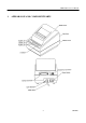
CBM-230/231 User’s Manual 4.4 Operation Panel 1. POWER LED(green) Illuminated when the power is supplied. 2. ERROR LED(red) Indicates different errors, depending on the illuminated or blinking condition.
CBM-230/231 User’s Manual 5. LF switch and power switch Self-printing is performed by turning on the power switch with the LF switch held down. 4.5 Opening the Auto Cutter(CBM-231) When the paper is jamming or when you open the auto cutter in order to clean the head, raise the auto cutter, pulling the cutter lock lever in the direction of the arrow. [Caution] Immediately after printing, the printing head and motor have a high temperature.
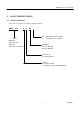
CBM-230/231 User’s Manual 5. SETTING OF DIP SWITCHES The DIP switches are located in the position shown in the figure below. Unscrew and remove the DIP switch cover. [Caution] Turn off the power to set the DIP switch.
CBM-230/231 User’s Manual DS1-1 DS1-2 DS1-3 DS1-4 DS1-5 DS1-6 DS1-7 DS1-8 Paper cutter Cover open Auto loading Input buffer Paper near end Paper near end remainder 1 Paper near end remainder 2 CR switching DS2-1 DS2-2 DS2-3 DS2-4 DS2-5 DS2-6 DS2-7 DS2-8 Print density Print density International character Unused International character International character International character International character DS3-1 DS3-2 DS3-3 DS3-4 Bit length Parity Odd / even DTR / XON-XOFF DS4-1 DS4-2 DS4-3 DS4-4 Bau
CBM-230/231 User’s Manual 6. PARALLEL INTERFACE 6.1 Specifications Data input method : 8-bit parallel(DATA 1-8) Control signal : ACK, BUSY, STB, FAULT, PE, RESET Applicable connectors : Printer side : 57LE-40360(equivalent to amphenol) Cable side : 57-30360(equivalent to amphenol) 6.2 Connector's Pin Configuration No. 1 2 3 4 5 6 7 8 9 10 11 12 13 14 15 16 17 18 Signal Name STB DATA 1 DATA 2 DATA 3 DATA 4 DATA 5 DATA 6 DATA 7 DATA 8 ACK BUSY PE +5V DC GND FRAME GND No.
CBM-230/231 User’s Manual 6.3 Input / Output Signals 6.3.1 Input / Output Signals (1) Input signals to the printer • DATA : This is an 8-bit parallel signal (Positive logic) • STB : This is a strobe signal to read in 8-bit data (Negative logic) • RESET : This signal resets the entire printer (Negative logic) 1 ms or more (2) Output signals from the printer • ACK : This is an 8-bit data request signal.
CBM-230/231 User’s Manual 6.3.2 Electrical Characteristics (1) Input signal level All input signals are at the TTL level. "HIGH" level: 2.0 V at minimum "LOW" level : 0.8 V at maximum (2) Output signal level All output signals are at the TTL level. "HIGH" level: 2.4 V at minimum "LOW" level : 0.4 V at maximum (3) Input/output conditions All input signals are pulled up at 3.3 kΩ. All output signals are pulled up at 3.3 kΩ.
CBM-230/231 User’s Manual 6.3.3 Timing Chart (1) Data input and printing timing T1, T2, T3 0.5 MIN T4 270 ns MAX T5 TYP T6 500 ms MIN (at power on) 6.3.4 Data Receiving Control When the BUSY signal is at LOW, the data from the host side can be received, but when at HIGH, it cannot be received. 6.3.5 Buffering A size of the input buffer can be selected by setting the DIP switch segment DS1-4.
CBM-230/231 User’s Manual 7. SERIAL INTERFACE 7.
CBM-230/231 User’s Manual 7.2 Connector's Pin Configuration No. 1 7 3 20 2 6 [Cautions] Signal Name FG GND RD DTR TD DSR Input/Output Function Frame Grand Signal GND Receiving data Printer BUSY signal Transmission data Data set ready Input Output Output Input 1. RS-232C signals are based on the EIA RS-232C. 2. When no data is being transferred, the receive data should be always maintained in the mark state.
CBM-230/231 User’s Manual 7.3 Input / Output Signals 7.3.1 Input / Output Signals (1) RD This is a serial receive data signal. When there is a framing error, overrun error, or parity error, that data is printed as "?." (2) DTR Write the data or a command when this signal is ready. If you write while it is busy, the data will be ignored, resulting in an overrun error. The data can be written into the input buffer even during printing.
CBM-230/231 User’s Manual 7.3.2 Data Configuration (1) (2) (3) (1) Start bit (2) Data bit(+ parity bit) (3) Stop bit(1 or more) (1) Start bit When half a bit has passed since a fall edge of a mark to a space, the state of the bit is read in again, and if it is a space, it will be recognized as a start bit. If it is a mark, it will not be recognized as the start bit. The start bit will be detected again without assuming it to be an error.
CBM-230/231 User’s Manual (2) Parity error When a parity check has been specified and an error is detected at parity check time, that data is stored in the buffer as "?." (3) Overrun error When an overrun error is detected, that data is stored in the buffer as "?." 7.3.4 Data Receiving Control When DTR/DSR control has been selected, if the DTR signal is at SPACE, the data from the host side can be received, but when at MARK, it cannot be received.
CBM-230/231 User’s Manual 7.3.
CBM-230/231 User’s Manual 8. DRAWER KICK CONNECTOR 8.1 Specifications (1) Drawer kick drive signal The pulses specified by ESC p are output. The state of the switch(+) can be known through the pin 34 of the interface connector when parallel interface is used, and through the ESC u command when the serial interface is used. (2) Electrical characteristics 1) Drive voltage : DC 24 V 2) Drive current : 0.8 A at maximum(should be within 510 ms) 3) Switch signal : Signal level "L" = 0 to 0.
CBM-230/231 User’s Manual 9. PRINT CONTROL FUNCTION 9.
CBM-230/231 User’s Manual 9.2 Input Data Format (1) Horizontal Tab Command (HT) Code : [09]h Mones the printing position to the next horizontal tab position The horizontal tab position is set by ESC D. The initial setting of the horizontal tab position is every 8 characters (9th columns, 17th columns, 25th columns, 33rd columns, 41st columns) of Font A. (2) Print command (CR) Code : [0D]h 1) When the DIP switch segment DS1-8 is set to OFF This command is ignored.
CBM-230/231 User’s Manual (5) Specifying collectively the print mode (ESC ! n) Code : [1Bh] + [21h] + n * {0 ≤ n ≤ FF} The data is described with the hexadecimal code. Specifies the print mode. Each bit of n has the following meaning.
CBM-230/231 User’s Manual (7) Defining the download characters (ESC & s n m a {D1 D2 ~ Dn}) Code : [1B]h + [26]h + s + n + m +a + Dn * {s = 03} {20 ≤ n ≤ 7E} {20 ≤ m ≤ 7E} {For the Font A; 0 ≤ a ≤ 0C, For the Font B; 0 ≤ a ≤ 09} The data is described with the hexadecimal code. Defines the font for the download characters of alphanumeric characters. • "s" denotes the number of bytes in the vertical direction. • "n" denotes a start character code, and m denotes an end character code.
CBM-230/231 User’s Manual [Example] For the Font A 31 CITIZEN
CBM-230/231 User’s Manual For the Font B 32 CITIZEN
CBM-230/231 User’s Manual (8) Specifying the bit Image (ESC * m n1 n2 D1 ~ Dn) Code : [1B]h + [2A]h + m + n1 + n2 + Dn * {m= Bit image mode (refer to the table below)} {0 ≤ n1 ≤ FF} {0 ≤ n2 ≤ 02} The data is described with the hexadecimal code. Prints the data in the form of bit image in accodance with the bit image mode specified by "m". • The number of bit printed is divided by 256, and n2 and is assumed to be a quotient, and n1 to be the remainder.
CBM-230/231 User’s Manual The following shows the relations between the bit image data and printed dots.
CBM-230/231 User’s Manual (9) Specifying/canceling the underline (ESC – n) Code: [1B]h + [2D]h + n * {0 ≤ n ≤ 02} The data is described with the hexadecimal code. Specifying or cancels the underline. • An underline is provided for the entire printed character width except a portion skipped by HT. • The 90°- right-turned characters are not underlined. • The following table lists the types of underlines deponing on the values an initial value is "1".
CBM-230/231 User’s Manual (13) Setting the horizontal tab position (ESC D n NUL) Code : [1B]h + [44]h + n [00]h * {0 ≤ n ≤ FF} The data is described with the hexadecimal code. Sets the horizontal tab position. • "n" denotes the number of columns from the beginning to the horizontal tab position. At this time, "n" is the setting position minus 1. • The tab position is set in the position of the character width × n from the beginning of the line.
CBM-230/231 User’s Manual (15) Specifying/canceling double printing (ESC G n)| Code : [1B]h + [47]h + n * {0 ≤ n ≤ FF} The data is described with the hexadecimal code. Specifying/canceling the double printing. • Only the lowest bit (n0) is effective for "n". • The following table list the controls by "n". n0 Type 0 Cancels double printing. 1 Specifies double printing. • The printing results of double printing and highlighted printing are exactly the same. .
CBM-230/231 User’s Manual Selecting the international characters. • Depending on the values of "n", following c haracter sets are specified. n (Hex) Character Set 0 U.S.A. 1 France 2 Germany 3 U.K. 4 Denmark I 5 Sweden 6 Italy 7 Spain 8 Japan 9 Norway A Denmark II • An initial value of "n" is specified by the DIP switches (DS2 -5.6.7.
CBM-230/231 User’s Manual (19) Setting of paper near end sensor available for print stop (ESC c 4 n) Code : [1B]h + [63]h + [34]h + n * {0 ≤ n ≤ FF} The data is described with the hexadecimal code. Specifying the condition of paper near end sensor to stop printing operation. • Only the lowest bit (n0) is effective for "n". • The bit of "n" has the followings meaning. n0 Type 0 Paper near end disabled 1 Paper near end enabled • An initial value of "n" is specified by the DIP switch (DS1 -5).
CBM-230/231 User’s Manual (21) Printing and feeding the paper by n-lines (ESC d n) Code : [1B]h + [64]h + n * {0 ≤ n ≤ FF} The data is described with the hexadecimal code. Prints the data in the print buffer and feeds the paper by n-lines. • A set rate does not remain. • The beginning of the line is assumed to be the next printing start position.
CBM-230/231 User’s Manual (23) Selecting Character Code Table (ESC t n) Code : [1B]h + [74]h + n * {0 ≤ n ≤ 1} The data is described with the hexadecimal code. Selecting Page n on the character code table: • "n" has the following meanings. n (Hex) Type 0 IBM character No. 2 (24) Transmitting the printer status (ESC v) Code : [1B]h + [76]h Transmits the current printer status. • The transmitted status is of 1 byte and its contents are as shown in the table below.
CBM-230/231 User’s Manual (25) Transmitting the status of the peripheral device (ESC u n) Code : [1B]h + [75]h + n * {n = 0} Transmits the current status of connector pin No.3. • "n" has the following meanings. n (Hex) Type 0 Drawer kick connector No. 3 • The transmitted status is of 1 byte and its contents are shown in the table below. • When nothing is connected to the connector, The bit 0 of "n" is always "1".
CBM-230/231 User’s Manual (26) Specifying/Canceling the inverted Characters (ESC {n) Code : [1B]h + [7B]h + n * {0 ≤ n ≤ FF} The data is described with the hexadecimal code. Specifying/canceling inverted characters. • "n" is valid only for the lowest bit (n0). • Bit n (n0) means the followings. n0 Type 0 Cancels the inverted characters 1 Specifies the inverted characters • Effective only when specified at the beginning of the lin e. • Printing example are shown below. • An initial value of "n" is "0".
CBM-230/231 User’s Manual (28) Specifying Absolute Positions (ESC $ n1 n2) Code : [1B]h + [24]h + n1 + n2 * {0 ≤ n1 ≤ FF} {0 ≤ n2 ≤ 1} The data is described with the hexadecimal code. Specifies the printing start position in terms of the number of dots from the beginning of the line (in an increment of 1/203 inch). • The number of dots is divided by 256, and a quotient is assumed to be n2, and the remainder to be n1. Therefore, the printing start position is n1 + n2 × 256 from the beginning of the line.
CBM-230/231 User’s Manual (30) Printing the bar code (GS k n Dn NUL) Code : [1D]h + [6B]h + n + Dn + [00]h * {0 ≤ n ≤ 7} The data is described with the hexadecimal code. Selects the bar code system and prints the bar code. • The beginning of the line is assumed to be the next printing start position. • selects the bar code system listed in the table below, depending on the valu es of "n". • Dn denotes the characters to be printed.
CBM-230/231 User’s Manual (31) Selecting Bar Code width (GS w n) Code : [1D]H + [77]H + n * {2 ≤ n ≤ 4} The data is described with the hexadecimal code. Selects the horizontal size of the bar code. • An initial value of the horizontal size is "3". (32) Selecting the height of the bar code (GS h n) Code : [1D]H + [68]H + n * {1 ≤ n ≤ FF} The data is described with the hexadecimal code. Selects the height of the bar code. • "n" denotes the number of dots in the vertical direction.
CBM-230/231 User’s Manual (34) Selecting the font of the HRI characters (GS f n) Code : [1D]h + [66]h + n * {0 ≤ n1 ≤ 1} The data is described with the hexadecimal code. Select the font of the HRI characters when printing the bar code. • "n" has the following meanings. n (Hex) Font 0 Font A 1 Font B (35) Defining the download bit image (GS * n1 n2 Dn) Code : [1D]h + [2A]h + n1 + n2 + Dn * {0 ≤ n1 ≤ FF} {0 ≤ n2 ≤ 30} {n1 × n2 ≤ 51F} The data is described with the hexadecimal code.
CBM-230/231 User’s Manual • The folloeing figure shows the relations between the bit image data and defined dots. (34) Printing Download Bit Image (GS / m) Code : [1D]h + [2F]h + m * {0 ≤ m ≤ 3} The data is described with the hexadecimal code. Prints the download bit images in the mode specified by "m". • The following table lists the mode selected by "m". m Mode Name 0 Normal mode 1 Hor. double mode 2 Vert.
CBM-230/231 User’s Manual (37) Starting/ending the macro definition (GS :) Code : [1D]h + [3A]h Specifies a starti or end of macro definition. Up to 2,048 bytes can be defined as macro. The bytes exceeding 2,048 bytes cannot be defined. • The definition is not cleared even if ESC @ (initializing the printer) is executed. Therefore, ESC @ can be included in the definition.
CBM-230/231 User’s Manual • When this command is accepted during macro definition, it means cancellation of macro definition. When this time done, the definition is cleared. • Nothing is executed when the macro has been undefined or n1=0 has been set. • When n3 = 1 is set and the macro is being executed, the paper cannet be fed by the paper feed switch. (39) Data input control (ESC = n) Code : [1B]h + [3D]h + n * {0 ≤ n ≤ FF} The data is described with the hexadecimal code.
CBM-230/231 User’s Manual (41) Full cut (ESC i) Code : [1B]h + [69]h Cuts the paper fully. • Effective only when this is entered at the beginning of the line. • CBM-231 only. (42) Partial cut (ESC m) Code : [1B]h + [6D]h Cuts the paper partially. • Effective only when this is entered at the beginning of the line. • CBM-231 only.
CBM-230/231 User’s Manual 10. Character Code Table 10.
CBM-230/231 User’s Manual 10.
CBM-230/231 User’s Manual Appendix 1. PRECAUTIONS AND MAINTENANCE 1.1 Precaution for Handling the Printer Mechanism 1. Use of unspecified paper may not assure you of printing quality and product life. 2. With the printing head kept down, do not turn the paper feed knob or pull out the paper. 3. Do not touch the heating element's surface of the head. 1.2 Precautions for Handling the Thermal Paper 1. A contact of chemicals or oil may discolor or erase the record. 2.
CBM-230/231 User’s Manual 1.5 Eliminating the Paper Powder When the printer is contaminated with paper powder, clean it with a brush or vacuum cleaner. [Caution] 1.6 Do not touch the printing head or motor immediately after printing because they are very hot. Cleaning the Head 1. Open the auto cutter and move up the printing head.(CBM-231) 2. Use the cardboard and gauze as shown in the figure below. 3.
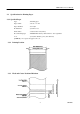
CBM-230/231 User’s Manual Appendix 2. External Dimensions 1.
CBM-230/231 User’s Manual 2.
CBM-230/231 User’s Manual Appendix 3.
Information Systems Division CBM Bldg., 5-68-10, Nakano, Nakano-ku, Tokyo 164-0001, Japan Head Office Tel: (+81-3) 5345-7540 Fax: (+81-3) 5345-7541 21E-20000208-1000-0064-07.