
User's Manual Line Thermal Printer CBM-270


CBM-270 User’s Manual
CONTENTS
1. OUTLINE.........................................................................................................................................................15
1.1 Features......................................................................................................................................................................15
1.2 Unpacking..................................................................................................................................................................15
2. BASIC SPECIFICATIONS ..............................................................................................................................16
2.1 Model Classifications................................................................................................................................................. 16
2.2 Basic Specifications...................................................................................................................................................17
2.3 Paper Specifications...................................................................................................................................................18
2.3.1 Recommended Paper.........................................................................................................................................18
2.3.2 Printing Position................................................................................................................................................ 19
2.3.3 Head and Paper Cutter Layout..........................................................................................................................19
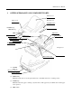
3. OUTER APPEARANCE AND COMPONENT PARTS....................................................................................20
4. OPERATION...................................................................................................................................................22
4.1 Connecting AC Adapter............................................................................................................................................. 22
4.2 Connecting Interface Cable........................................................................................................................................ 23
4.3 Inserting the Paper .....................................................................................................................................................24
4.4 How to Remove Remaining Paper Roll.....................................................................................................................25
4.5 Eliminating the Paper Jam ......................................................................................................................................... 26
4.6 FEED Switch Function .............................................................................................................................................. 27
4.6.1 When Thermal Paper is Used............................................................................................................................27
4.6.2 When Label Paper is Used................................................................................................................................27
4.6.3 When the Macro is Executed ............................................................................................................................27
4.6.4 When the Label is Fed to the Paper Cutting Position by the Command...........................................................27
4.7 Paper End Function....................................................................................................................................................27
4.8 Paper Near End Function........................................................................................................................................... 28
4.9 Auto-Loading Function.............................................................................................................................................. 29
4.10 Self-Print Function..................................................................................................................................................... 29
4.11 Operation Panel and Display of Error........................................................................................................................ 30
4.12 Red/Black Print (Precations for use)..........................................................................................................................31
5. DIP SWITCH SETTING..................................................................................................................................32
5.1 Location of DIP Switch..............................................................................................................................................32
5.2 DIP Switch Function..................................................................................................................................................32
5.3 Jumper Wire Function................................................................................................................................................ 33
6. PARALLEL INTERFACE ...............................................................................................................................34
6.1 Specifications.............................................................................................................................................................34
6.2 Connector's Pin Configuration................................................................................................................................... 34
6.3 Input and Output Signals............................................................................................................................................35
6.3.1 Input and Output Signals...................................................................................................................................35
6.3.2 Electrical Characteristics...................................................................................................................................36
6.3.3 Timing Chart..................................................................................................................................................... 37
6.3.4 Data Receiving Control.....................................................................................................................................37
6.3.5 Buffering........................................................................................................................................................... 37
7. SERIAL INTERFACE .....................................................................................................................................38
7.1 Specifications.............................................................................................................................................................38
7.2 Connector's Pin Configuration................................................................................................................................... 38
7.3 Input and Output Signals............................................................................................................................................39
7.3.1 Input and Output Signals...................................................................................................................................39
7.3.2 Data Configuration............................................................................................................................................40