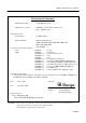
CBM-710/720/730/750 User’s Manual Declaration of Conformity Manufacturer’s Name : Japan CBM Corporation Manufacturer’s Address: CBM Bldg., 5-68-10, Nakano, Nakano-ku Tokyo, 164-0001, Japan Declare the Product Product Name: Model Number(s): Conform to the following Standards: LVD: EMC: Dot Matrix Printer CBM-710,720,750 Series (CBM-710R, CBM-710P, CBM-720R, CBM-720P, CBM-750R, CBM-750P) (S.No.
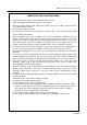
CBM-710/720/730/750 User’s Manual IMPORTANT SAFETY INSTRUCTIONS • Read all of these instructions and save them for future reference. • Follow all warnings and instructions marked on the product. • • Unplug this product from the wall outlet before cleaning. Do not use liquid or aerosol cleaners. Use a damp cloth for cleaning. Do not use this product near water. • Do not place this product on an unstable cart, stand or table. The product may fall, causing serious damage to the product.
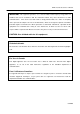
CBM-710/720/730/750 User’s Manual IMPORTANT: This equipment generates, uses, and can radiate radio frequency energy and if not installed and used in accordance with the instruction manual, may cause interference to radio communications. It has been tested and found to comply with the limits for a Class A computing device pursuant to Subpart J of Part 15 off FCC Rules, which are designed to provide reasonable protection against such interference when operated in a commercial environment.
CBM-710/720/730/750 User’s Manual CONTENTS 1. INTRODUCTION..................................................................................................................................................1 1. 1 Features .............................................................................................................................................1 1.2 Accessories .................................................................................................................................
CBM-710/720/730/750 User’s Manual 9. SERIAL INTERFACE ........................................................................................................................................25 9.1 Specifications ..................................................................................................................................25 9.2 Connector Pin Assignment..............................................................................................................26 9.
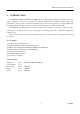
CBM-710/720/730/750 User’s Manual 1. INTRODUCTION The CBM-710, CBM-720, CBM-730 and CBM-750 are dot impact printers which can be utilized for a wide range of applications, such as data communications terminals, ECR terminals and kitchen printers. High speed performance is made possible by a bidirectional printing system and, since these printers are compact, lightweight and equipped with an abundance of functions, they can be easily employed for a variety of different tasks.
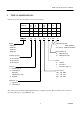
CBM-710/720/730/750 User’s Manual 2. TYPE CLASSIFICATIONS Printer types are classified according to the system shown below.
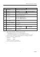
CBM-710/720/730/750 User’s Manual 3. SPECIFICATIONS 3.1 General Specifications Item CBM-710, 730 CBM-720, 750 1 Print Method Bidirectional serial dot impact method 2 Character composition 7 × 7 dots (1ncl. half-dots) 3 Character number per line 23 columns: 28 columns: 40 columns: 230 dot/line 280 dot/line 360 dot/line 4 Print speed 23 columns: 28 columns: 40 columns: approx.4.0 line/sec. approx. 3.5 line/sec. approx. 3.0 line/sec.
CBM-710/720/730/750 User’s Manual Item CBM-710, 730 CBM-720, 750 12 Validation Print Available only for V-Type (1 line print) 13 Auto cutter Without cutter 14 Cassette ribbon Two color (Black and Red) print IR-61R/B*4 15 Paper winder Model AW-2 available as option. 16 Power voltage*5 100V ± 10%, 50/60 Hz (For Japan) 115V ± 10%. 60 Hz (For United States) 230V ± 10%, 50/60Hz (For Europe) 17 Power consump. Approx. 30W 18 Operation temp.
CBM-710/720/730/750 User’s Manual 3.2 Print Format (1) Character Font 7 × 7 dot. 23 columns: W = Approx. 1.8 mm 40 columns: W = Approx. 1.36 mm 28 columns: W = Approx. 1.5 mm 7×7 dots (Incl. half-dots) 7×7 dots (Incl. half-dots) 3.3 Paper Specifications (1) Form Friction specification : Roll paper 76 - 0.5 mm (Width) × 80 mm (Outer dia.) Pin wheel specification: Fan fold paper Width 76 mm (3 inches) ~ 89mm (3.
CBM-710/720/730/750 User’s Manual 4.
CBM-710/720/730/750 User’s Manual 5. EXTERNAL APPEARANCE AND PARS DESCRIPTIONS 5.1 CBM-710 External Appearance Fig. 1 Front View Fig.
CBM-710/720/730/750 User’s Manual 5.2 CBM-720 External Appearance Fig. 3 Front View Fig.
CBM-710/720/730/750 User’s Manual 5.3 CBM-730 External Appearance Fig. 5 Front View Fig.
CBM-710/720/730/750 User’s Manual 5.4 CBM-750 External Appearance Fig. 7 Front View Fig.
CBM-710/720/730/750 User’s Manual 5. 5 Part Descriptions (1) Power Cord Attach the connector end to the printer inlet, and insert the plug end into an electric outlet. (2) Inlet This is the electric power inlet. Attach the connector end of the power cord here. (3 ) Power Switch Power is supplied to the printer by turning this switch on. (4) Line Switch When this switch is pressed, the printer enters select (on line) status. When pressed again, the printer enters deselect (off line) status.
CBM-710/720/730/750 User’s Manual 6. OPERATION 6. 1 Setting and Removing the Paper and Ribbon Covers 1) To open, grasp the sections of the cover with both hands and lift upward. 2) In order to replace the cover, engage the hook section in the middle and press downward in the direction of the arrow. Fig. 9 3) To open the CBM-750's printer cover, grasp the Fig. 10 (lines-engraved) section with both hands and lift upward.
CBM-710/720/730/750 User’s Manual 6.2 Opening and Closing the Cutter Unit (CBM-720. CBM-750) 1) To open the unit, grasp two levers and lift upward. 2) When closing the unit, press downward until it completely locks into place. Fig.
CBM-710/720/730/750 User’s Manual 6.3 Installing the Cassette Ribbon 1) First remove the ribbon cover (CBM-710, CBM-730). In the case of the CBM-720, 750 remove both the ribbon and paper covers and then open the cutter unit. (Refer to figures 9, 10 &11.) 2) While inserting the ribbon into the space between the print head and the ribbon guide, press the cassette into the holder unit until it clicks into place. (Refer to figure 12 & 13.
CBM-710/720/730/750 User’s Manual 6.4 Installing and Changing the Paper (1) Installing the Paper 1) Remove the paper cover. 2) Put the end of the paper off at a right angle as shown in figure 14. Fig. 14 3) Put the end of the paper into the paper entrance of the printer. (Refer to figure 17.) 4) After turning the power switch on and confirming that the printer is in deselect (off line) status, press the LF switch to feed the paper into the printer.
CBM-710/720/730/750 User’s Manual Fig. 15 Fig. 16 Hook some of the paper's perforations on the sprockets and forward the paper into the printer by turning the paperfeed knob until the paper's tip protrudes 5 - 6 cm from the printer. In the case of the CBM-710, use the LF switch to feed the paper.
CBM-710/720/730/750 User’s Manual 6) When using the paper winder mechanism (AW-2), feed the paper toward the rear of the printer from the inside of the paper cover, and secure it to the take -up spool. Fig. 17 7) In the case, of the CBM-720, attach the printer cover, press the LFswitch, and confirm that the paper comes out of the paper exit.
CBM-710/720/730/750 User’s Manual (2) Changing the Paper 1) Cut off the remaining paper near the entrance to the printer. 2) If the alarm lamp is on, turn it off by pressing the line switch. 3) Feed the paper out of the printer by pressing the LF switch or p ull it out from the paper exit. 4) Install a new paper roll. (Refer to section 6.4 (1) Installing the paper.) 5) When the line switch is pressed again, the printer enters select (on line) status and printing may be resumed once again. 6.
CBM-710/720/730/750 User’s Manual 6.7 Installation of the CBM-750 1) Table-top use Put the AC cord into the "T" hole of the bottom base. Install the base stoppers, as shown in the figure 19. Fig. 19 2) Wall-mounting use Fix the hanger with 2 screws to the wall and hook the unit as shown in the figure 20. Fig.
CBM-710/720/730/750 User’s Manual 7. INPUT BUFFER BACK-UP FUNCTION 7.1 Input Buffer Back-up If the power is turned off, or there is a power failure during printing, the data in the input buffer will be retained. When the power comes back on, the power failure symbol (..... PD) will be printed in red, and then the data which was interrupted will be printed from the beginning of the line where the interruption occurred.
CBM-710/720/730/750 User’s Manual 8. PARALLEL INTERFACE 8.1 Specifications a) Data Input system: 8 bit parallel (DATA 1 - 8). b) Control Signals: ACK, BUSY, STB, FAULT, PE, RESET c) Compatible Connectors: Cable side: Printer side: 57LE-40360 (AMPHENOL or equivalent) 57-30360 (AMPHENOL or equivalent) 8.2 Connector Pin Assignment Pin No.
CBM-710/720/730/750 User’s Manual 8.3 Description of Input/Output Signals (1) Input/Output Signals a) Input Signals (To Printer) *DATA : 8 bit parallel signal. (Positive logic) *STB : A strobe signal for reading in 8 bit data. (Negative logic) *RESET : A signal which resets the entire printer. (Negative logic. 1 ms or more) b) Output Signals (From Printer) *ACK *BUSY *FAULT *PE : This is a pulse signal for requesting 8 bit data, issued at the end of a BUSY signal.
CBM-710/720/730/750 User’s Manual (2) Electrical Characteristics a) Input Signal Level All input signals are TTL level. "HIGH" level ................ 2.0V Min. "LOW" level .................. 0.8V Max. b) Output Signal Level "HIGH" level ................. 2.4V Min. "LOW" level .................. 0.4VMax. c) Input/Output Conditions All of the input signals are pulled up by 1K ohms. All of the output signals are pulled up by 3.3K ohms.
CBM-710/720/730/750 User’s Manual (3) Timing Chart a) Data Input and Print Timing (4) Data Receiving Control Your printer is able to receive data sent from the host side when the BUSY signal is LOW, but unable to receive when the BUSY signal is HIGH. (5) Buffering 1) N Type Your printer is provided with a two line input buffer. 2) B Type Your printer is provided with a 7K byte input buffer.
CBM-710/720/730/750 User’s Manual 9. SERIAL INTERFACE 9.
CBM-710/720/730/750 User’s Manual 9.
CBM-710/720/730/750 User’s Manual 9.3 Description of Input/Output Signals (1) Input/Output Signals a) RD : This is the serial signal for received data. When framing, overrun or parity errors occur, the data concerned are ignored. b) DTR : Please write in data or commands when this signal is in a "ready" state. If written in when in a BUSY state, an overrun error will occur and the data will be ignored. Data can be written into the input buffer even during printing.
CBM-710/720/730/750 User’s Manual (2) Data Composition [1] Start bit [2] Data bits (and parity bit) [3] Stop bit (1 bit or more) [1] Start bit 1/2 bit past the line dropping from MARK to SPACE, a status reading is taken again. If the reading is SPACE, a start bit is recognized, but if it is MARK, it is not taken as a start bit. This is not regarded as an error, but the search for the start bit is performed once again.
CBM-710/720/730/750 User’s Manual [4] Other errors When trouble is detected in the printer mechanism, the ALARM lamp goes on, the buzzer is sounded, the FAULT signal is output, and the DTR signal becomes BUSY. After the cause of the trouble has been corrected, the ALARM lamp can be turned off by pressing the LINE switch or by making RESET = "0". When the printer is put ONLINE, data receiving restarts.
CBM-710/720/730/750 User’s Manual (6) Electrical Characteristics a) RS-232C Circuit Input (RD) MAX232 or equivalent Mark = (-8V): Stop bit Space = (-8V): Start bit Output (DTR, TD, FAULT) MAX232 or equivalent *DTR (–8V): (+8V): *FAULT (–8V): (+8V): BUSY READY Normal Abnormal *TD Mark = (–8V): 1 Space = (+8V): 1 30 CITIZEN
CBM-710/720/730/750 User’s Manual b) Current Loop Circuit Input (RD) Mark Space = Current ON = Current OFF Output (DTR, TD) *DTR *TD Current ON : READY Current OFF : BUSY Mark = Current ON Space = Current OFF c) TTL Circuit Output (PE) 7406 or equivalent *PE H: L: Paper empty Paper reaming RESET 7406 or equivalent LOW for RESET 31 CITIZEN
CBM-710/720/730/750 User’s Manual 10. FUNCTION SELECTION In order to meet the widest possible range of needs, various conditions can be selected by setting the DIP switches and slide switches. (1) Setting DIP Switch DS1 No.
CBM-710/720/730/750 User’s Manual (2) DIP Switch DS2 (Serial interface specifications only) No .
CBM-710/720/730/750 User’s Manual (3) Slide Switch Setting (Serial interface specifications only) RS232-C or 20mA current loop can be selected by changing slide switch SW1 on the control board. The side labeled "RS" is for RS232-C and the side, labeled "CL" is for 20mA current loop. The switch is set at the factory for RS232-C. (4) DIP Switch and Slide Switch Locations DIP switches and slide switches are mounted on the control board to make function selection possible.
CBM-710/720/730/750 User’s Manual 11. PRINT CONTROL FUNCTIONS 11.1 Control Codes Function cord Hex.
CBM-710/720/730/750 User’s Manual 11.2 Input Data Formats (1) Paper feed command for "n" lines D8 1st byte 0 D1 0 0 0 1 1 0 D8 2nd byte 0 FF (0C)H + n D1 N7 N6 N5 N4 N3 N2 N1 N7 ~ N1 (Binary digits) When the number of lines to be fed (2hd byte) is written-in following the paper feed command (1st byte), the paper will be fed by the number of lines specified. The number of lines to be fed can be specified from n=1 to 127. If "0" is specified, paper feed will not be carried out.
CBM-710/720/730/750 User’s Manual (3) Enlarged character cancel command D8 0 D1 0 0 0 1 1 1 1 SI (0F)H This command is used or canceling e enlarge character mode set by SO, and the following data will be printed out in the normal character mode. (4) Paper feed command D8 0 D1 0 0 0 1 0 1 0 LF (0A)H When there is data in the internal print buffer, line feed will be carried out after printing is completed. When the buffer is empty, line feed only will be carried out.
CBM-710/720/730/750 User’s Manual (8) Initial Set Command D8 0 D1 0 0 1 0 0 0 1 DC1 (11)H The controller is initialized by this command and the following conditions are established.
CBM-710/720/730/750 User’s Manual (11) Underline Command D8 1st byte 0 D1 0 0 1 1 0 1 D8 2nd byte 0 1 ESC (1B)H D1 0 1 0 1 1 0 D8 1 – (2D)H D1 3rd byte N1 n (Binary digital) When n=1, the underline mode is set, and when n=0, it is cancelled.
CBM-710/720/730/750 User’s Manual However, since "half-dots" are being used, the next corresponding pin cannot print at the same time. Further, the maximum value of n1 and n2 is the number contained in one line, and this cannot be exceeded.
CBM-710/720/730/750 User’s Manual (15) Page Length Set Command D8 1st byte 0 D1 0 0 1 1 0 1 D8 2nd byte 0 ESC (1B)H D1 1 0 0 0 0 1 D8 3rd byte 1 1 C (43)H D1 N7 N6 N5 N4 N3 N2 N1 n (Binary digital) The length of one page is set to "n" lines by this command.
CBM-710/720/730/750 User’s Manual (17) Skip Perforation Command D8 1st byte 0 D1 0 0 1 1 0 1 D8 2nd byte 0 ESC (1B)H D1 1 0 0 1 1 1 D8 3rd byte 1 0 N (4E)H D1 N7 N6 N5 N4 N3 N2 N1 n (Binary digital) This command feeds the paper (skips) n lines without any printing.
CBM-710/720/730/750 User’s Manual (18) Full Cut Command D8 1st byte 0 D1 0 0 1 1 0 1 D8 2nd byte 0 0 ESC (1B)H D1 1 0 1 0 0 0 D8 3rd byte 1 0 P (50)H D1 0 0 0 0 0 0 0 0 (00)H A full cut of the paper is performed by this command (one connecting point remaining).
CBM-710/720/730/750 User’s Manual 12. CHARACTER CODE TABLES International Character Codes The following codes are set as space characters. 20H, 80H-9FH, E0H-FFH.
CBM-710/720/730/750 User’s Manual Individual Country Character Codes 45 CITIZEN
CBM-710/720/730/750 User’s Manual 13. MAINTENANCE 13.1 Maintenance Procedures It is recommended that users perform periodic cleaning of their printer. (1) Exterior : The exterior case of the printer can be cleaned with alcohol. Care should be taken to keep water from reaching the electronic parts and the printing mechanism . (2 ) Interior : There is no particular requirement, however, when the printer case is opened to change settings etc.
CBM-710/720/730/750 User’s Manual 14. EXTERNAL DIMENSIONS 14.
CBM-710/720/730/750 User’s Manual 14.
CBM-710/720/730/750 User’s Manual 14.
CBM-710/720/730/750 User’s Manual 14.
CBM-710/720/730/750 User’s Manual 14.
Information Systems Division CBM Bldg., 5-68-10, Nakano, Nakano-ku, Tokyo 164-0001, Japan Head Office Tel: (+81-3) 5345-7540 Fax: (+81-3) 5345-7541 27-20000208-0500-0040-010.