
Line Thermal Printer User's Manual CBM1000


— 22 —
ENGLISH
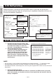
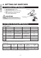
1 Turn off the power of the printer.
2 Open the printer cover.
3 Remove the paper roll and the DIP switch
cover.
4 After completing the setting, place the
cover to the original position.
4. SETTING DIP SWITCHES
* DIP switch 3 is only for the
serial interface.
CAUTION
• Do not make settings while the printer is
turned on.
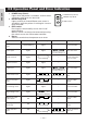
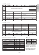
4.2 Table for Setting DIP Switches
4.2.1 DIP switch 1
4.1 Location of DIP Switches
DIP switch cover
No. Function ON OFF Factory presetting
1-1
1-2
1-3
1-8
1-7
1-6
1-5
1-4
Auto cutter
Unused
Paper width
Input buffer
CR mode
Print columns*
Print density (See the tabel below.)
Available
-
58 mm
72 bytes
LF operation
42 columns (80 mm)
30 columns (58 mm)
Not available
-
80 mm
4K bytes
Ignored
48 columns (80 mm)
36 columns (58 mm)
ON
OFF
OFF
OFF
ON
OFF
OFF
OFF
* It will be different according to the setting of paper width (DS1 – 3).
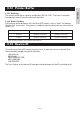
Level 4
(Dark)
Note: If print density is set to level 2 (Standard) or over, print speed may decrease.
Print density
Level 1
(Light)
Level 2
(Standard)
Level 3
(Slightly dark)
No.
1-7
1-8
OFF
OFF
ON
OFF
OFF
ON
Print density
ON
ON